采用增量成形工艺将圆管加工成方形截面件
来源期刊:中国有色金属学报(英文版)2019年第11期
论文作者:F. RAHMANI S. M. H. SEYEDKASHI S. J. HASHEMI
文章页码:2351 - 2361
关键词:管材增量成形;方形截面;径向进给;轴向进给;减薄
Key words:tube incremental forming; square cross-section; radial feed; axial feed; thinning
摘 要:增量成形是近年来发展起来的一种管材成形工艺。如果能确定工艺参数和最优值的影响,可以优化制造成本和加工精度。将圆形铜管通过增量成形工艺变为方形截面,设计球形成形冲头和管材夹具实验装置。成形冲头的运动由数控机床控制,为了确定刀具线速度、径向进给和轴向进给等工艺参数对方形截面减薄率和最大外径的影响,进行全因子试验设计。结果表明,径向进给对减薄率的影响最大,而轴向进给对最终轮廓的影响最大;径向进给量增大,减薄效果更好;轴向进给量越小,形状一致性越好;而线速度对减薄率没有显著影响。还给出预测响应的回归模型。
Abstract: Incremental forming process is recently developed to form tubular parts. The fabrication cost and accuracy could be optimized if the effects of process parameters and the optimum values are specified. The aim of this research is using incremental forming of copper tubes to convert a circular tube into a square cross-sectional part. An experimental setup, consisting of a spherical forming punch and a fixture for clamping the tube is designed. The forming punch movement is controlled by a CNC machine. Full factorial design of experiments is carried out in order to determine the effects of process parameters including linear velocity, radial feed, and axial feed of the tool on the thinning ratio and the maximum outer diameter of the square cross-sectional parts. Results show that the radial feed has the major influence on the thinning ratio, while the axial feed plays the major role for the final profile. Increase of radial feed results in higher thinning ratio, and decrease of axial feed results in better shape conformity. Linear velocity does not have a significant effect on thinning ratio. Regression models are also given for predicting the determined responses.
Trans. Nonferrous Met. Soc. China 29(2019) 2351-2361
F. RAHMANI1, S. M. H. SEYEDKASHI1, S. J. HASHEMI2
1. Mechanical Engineering Department, University of Birjand, Birjand 97175-376, Iran;
2. Department of Mechanical Engineering, Faculty of Enghelab-e Eslami, Tehran Branch, Technical and Vocational University (TVU), Tehran 13715-173, Iran
Received 25 February 2019; accepted 10 June 2019
Abstract: Incremental forming process is recently developed to form tubular parts. The fabrication cost and accuracy could be optimized if the effects of process parameters and the optimum values are specified. The aim of this research is using incremental forming of copper tubes to convert a circular tube into a square cross-sectional part. An experimental setup, consisting of a spherical forming punch and a fixture for clamping the tube is designed. The forming punch movement is controlled by a CNC machine. Full factorial design of experiments is carried out in order to determine the effects of process parameters including linear velocity, radial feed, and axial feed of the tool on the thinning ratio and the maximum outer diameter of the square cross-sectional parts. Results show that the radial feed has the major influence on the thinning ratio, while the axial feed plays the major role for the final profile. Increase of radial feed results in higher thinning ratio, and decrease of axial feed results in better shape conformity. Linear velocity does not have a significant effect on thinning ratio. Regression models are also given for predicting the determined responses.
Key words: tube incremental forming; square cross-section; radial feed; axial feed; thinning
1 Introduction
Over the past few years, extended investigations have been performed on incremental sheet metal forming (ISMF) process. In this process, a numerical control method is utilized to form a sheet with a step-wise pattern. This is a flexible die-less process, in which a sheet metal is gradually formed as the tool moves in an open space. The forming magnitude is enhanced in this process because there is a localized forming region, and the forming forces are concentrated on the contact point of the tool and the sheet [1]. Single point incremental forming (SPIF) is one of the ISMF techniques in which the sheet experiences an instant single forming force, and there is no local supporting point in the forming region [2]. In SPIF process, a hemispherical head tool moves in a defined path on the workpiece. The path is defined based on the final shape of the product. However, SPIF suffers from several limitations, such as high thinning ratio and low geometrical accuracy of the product [3]. Tool diameter, vertical feed (the vertical feed of the tool in a forming path) and movement path of the tool affect the SPIF thinning magnitude. Thus, using a multi-stage incremental strategy could be a useful option to decrease the thinning ratio. This strategy is dependent on the number of steps, and the shape of the sample at the end of each stage [3].
SKJOEDT et al [4] studied the influence of the tool movement direction in a multi-stage single point incremental forming on the strain distribution and thickness distribution of the final shape of a cylindrical cup product. They focused on a five-stage fabrication of the product, both numerically and experimentally, and showed a significant influence of the tool movement direction as an input parameter. SHI et al [5] investigated the formability of an aluminum alloy using the multi- stage incremental process of a varying wall angle conical and pyramid frustum test. CRISTINO et al [6] conducted an experimental investigation on the multi-stage single point incremental forming of a square hole-flanging products. They used overlapping circle grids to specify the effects of initial square hole sizes on the formability and strain path. Thickness distribution and mechanical properties of a truncated pyramid processed by incremental forming were investigated by LI et al [7] based on numerical simulation and tensile tests. The relation between the tool path and the minimum thickness was discussed as well as its location.
Nowadays, tubular products are being extensively used in different industries, such as automobile and aerospace. Hydroforming process is a useful process to form the non-circular tubes. Tube hydroforming (THF) is very famous compared to other similar processes. Determining the optimum process parameters to achieve the ideal final shapes is significantly studied by many researchers [8]. In tube hydroforming process, internal pressure of a fluid and axial feeding on the tube ends deform the tube cross-section. XU et al [9] studied the effects of coefficient of friction, strain-hardening exponent, and anisotropic coefficient on the thickness distribution of the high-pressure hydroforming of square sectional parts. CHOW and YANG [10] also predicted the conditions leading to the tube bursting with consideration of anisotropic effects. HASHEMI and RAHMANI [11] investigated the geometrical accuracy of rectangular sectional parts in the low-pressure THF Process.
However, high level of oil pressure, sealing difficulties and expensive equipment are disadvantages of the hydroforming process that limit its applications. Alternatively, a new forming process called incremental tube forming (ITF) is being studied in recent years. ITF process is a flexible forming process, in which a metal tube is formed step-wise by means of a forming tool. The tool moves in a specific path in contact with a tube, in which its movement is controlled by a computer-aided manufacturing (CAM) software. WEN et al [12] described how some defects, including plate warpage and buckling at flange section initiate in the incremental forming of aluminum flange. TERAMAE et al [13] investigated the incremental forming of a branched tubing with an oval hole in the tube. They also studied the effects of anisotropy value on the thickness distribution of the samples. As well, WEN et al [14] investigated the modes of the incremental forming of tubes comprising an expansion/reduction of the tube diameter, tube wall grooving, and hole flanging. They showed that elastic deformation originates a high spring-back value during the process.
MOHAMED et al [15] performed the flange forming process at the end part of the tube using a sphere-shaped tools on the lathe device. They expressed that an increase in the tool feed rate and the initial tube thickness increases the forming forces. The maximum thinning was observed at the flange edges. YANG et al [16] studied the hole-flanging process of a thin-walled tube for branching the tubes. They showed that the branching height depends on the outer diameter of the tube, and the pre-cut hole size and shape. HUSSAIN et al [17] studied the effects of pre-cut hole size of the blank on the formability of flanging in the incremental forming process. They produced a flange in four stages with different wall angles. They showed that the pre-hole size increases the hoop strain values on the flange, which accelerates the sample bursting. SEYEDKASHI et al [18] investigated a die-less incremental forming of the tubes using a rotary tool. The influence of different process parameters on the surface roughness and thickness distribution in the formed region was determined; an increase in the feeding depth led to a high surface roughness.
So far, the incremental forming of the square and rectangular cross-section tubes is not thoroughly studied yet. The scope of this research is to study the possibility of an incremental forming of a circular thin-walled tube for converting it into a square cross-section part. The forming tool moves in the square-shaped paths inside a circular tube. Thus, a design of experiments is carried out to specify the optimum values of the process parameters to achieve the least thinning ratio and the highest geometrical accuracy. So, the influence of the process parameters, including linear velocity, radial feed, and axial feed of the tool on the thinning ratio and the final shape of the products is investigated.
2 Experimental
A spherical-head tool is utilized as a forming tool to be moved inside the tube for converting it into a square cross-sectional part. The tool movement path is controlled by a CNC milling machine. A four-jaw chuck is used in order to clamp the tube during the die-less forming process (Fig. 1). A shaft with a sliding fitting condition is inserted into the tube to eliminate the wrinkling. This setup is fixed in a CNC milling machine, model FP4ME, with the forming tool mounted inside the spindle. Force is applied to the inner surface of the tube by the forming tool. A square-shaped path is then applied to the tool, defined by a G-code written according to the predetermined parameters. The experimental setup fixed in the CNC milling machine, including the four-jaw chuck mounted on the machine table and the forming tool, is illustrated in Fig. 2(a). A schematic image of a spherical-head tool with a diameter of 8 mm is shown in Fig. 2(b).
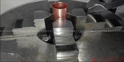
Fig. 1 Dependent four-jaw chuck for supporting tube
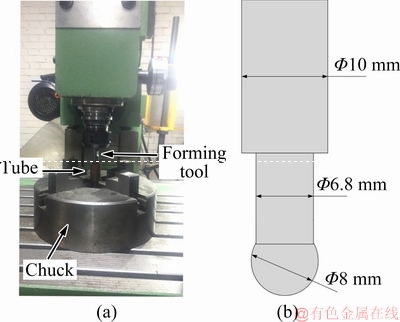
Fig. 2 Experimental forming setup (a) and forming tool dimensions (b)
The initial geometry of the tube and the ideal final shape is shown in Fig. 3. The outer diameter of the square tube (D), which is drawn in Fig. 3, is measured to specify the influence of the process parameters on the final profile, as well as the spring-back value of the tube. At first, the radial feeding of the tool is applied to the upper point of the tube and then, the whole square path is applied in order to form the first-stage of the process (with small forming magnitude). Since the tool path is generated by G-codes in the CNC machine, it passes each edge with a specified velocity but it has to slow down and stop at each corner to be able to start the next edge. The acceleration and deceleration time is small in comparison with the constant velocity path, so it is neglected and constant specified velocity is assumed for further discussion. Also, the spindle motor is off during the forming, so the tool can rotate freely around its axis due to the friction with the tube surface. Subsequently, further feed is applied in the direction of the tube axis (Pa) and the square path is repeated (Fig. 4(b)). In this study, the height of the final square-sectional part is considered equal to 15 mm. When applying the radial feed along the tube axis is finished, tool returns again to the start point in order to advance the further radial depth. As a result, the forming magnitude is increased. The radial difference between the sample sizes in the progressive stages is called Pr (Fig. 4(a)).
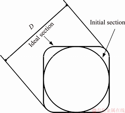
Fig. 3 Geometrical characteristics of ideal profile
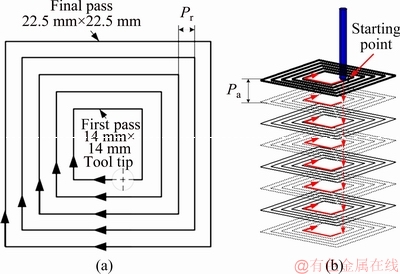
Fig. 4 Defined paths of tool from top view (a) and during incremental forming (b)
The linear velocity of the tool (V), when in contact with the tube, is another effective process parameter. The high levels of mentioned parameters (Pa, Pr and V) lead to a short process time, while it might reduce the geometrical accuracy of the product, which causes tube wrinkling and probable rupture.
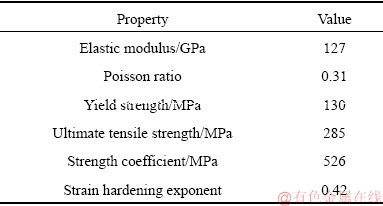
In this study, the tube samples have initial outer diameter of 22 mm and the wall thickness of 0.8 mm. Material properties of the annealed copper, listed in Table 1, are obtained by standard tube tensile test according to ASTM E8M [19]. Based on this standard, for all small tubes (≤25 mm in outer diameter), it is standard to use tensile test specimens of full size tubular sections. So, the same tube is used in tensile tests. Snug-fitting metal plugs are inserted into the ends of tube to permit the tensile test machine jaws to grip the specimen properly. Engineering stress-strain diagram of the material is also shown in Fig. 5.
Table 1 Mechanical properties of annealed copper tube
The cross-section of a sample product is shown in Fig. 6. A set of experiments, which will be explained in the following sections, are performed to determine the effects of process parameters on the final product. Formed samples are illustrated in Fig. 7. A fire resistant grease is used as a lubricant to reduce the friction forces at the contact point between the tool and the tube surface. Internal surface roughness of the tubes increases after the forming because of the friction at tool/wall interface. This is more obvious at the axial feed point because the downward movement of the tool in all forming passes is performed from the same point.
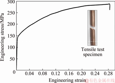
Fig. 5 Engineering stress-strain curve for Cu C11000
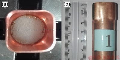
Fig. 6 Front (a) and side (b) views of formed product
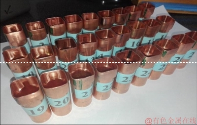
Fig. 7 Formed samples with various input parameters
A thickness gauge with the precision of 0.01 mm is used to measure the thickness of the tubes at the end of the process. Also, a CMM device is used to control the accuracy of the results and to compare the geometry of the final profiles. Figure 8 shows how the tube is mounted on the CMM and how the outer edge of the tube profile is measured by this device.
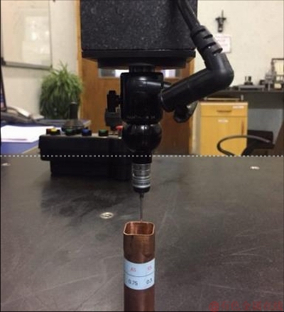
Fig. 8 Measurement using CMM device
The design of experiments (DOE) methodology is a statistical approach to determine the main and interaction effects of input parameters on output parameters. It helps predict the behavior and responses of a sophisticated process, which is dependent on several input variables. It is also capable of presenting such a prediction using the minimum number of experiments.
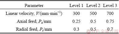
The effects of three different parameters, including linear velocity, radial feed, and axial feed of the tool on the thinning ratio and the maximum outer diameter of the square cross-sections are studied. The linear velocity of the tool is kept constant during the process. A full factorial design of experiments is used during the experiments. The first step in this methodology is to specify the input parameters and their levels, which are listed in Table 2. Total number of experiments for three parameters with three levels is 33=27. These 27 tests are performed in a completely randomized design (CRD) in order to minimize the noises.
Table 2 Input parameters and their levels
The fitting model is a function as a sum of finite terms. Each term consists of the parameter and its coefficient. This model could be defined as
y=β0+β1A+β2B+β3C+β12AB+β13AC+… (1)
where A, B and C are the input parameters and βi are their coefficients. The final model comprises the terms with significant effect on the response.
3 Results and discussion
3.1 Analysis of variance (ANOVA)
The measurements for thinning and diameter values are performed on the upper edge of the formed parts. Table 3 lists the CRD experiments and their corresponding results, including the thinning ratio and the maximum outer diameter of the square cross-sections.
The regression analysis is applied to fitting a polynomial equation through the experimental data. Figure 9 shows a comparison between the recognized output profiles using CMM and the ideal profile. It is obvious that the maximum spring-back occurs at the corner of the cross-sections, while the walls almost match the ideal profile. The best profile, which fits best the ideal shape (theoretical corner radius of 4 mm equal to the tool radius), is achieved when the linear velocity is 700 mm/min, the axial feed is 0.25 mm, and the radial feed is 0.7 mm. In this condition, the cross-section corner radius is almost 5.35 mm.
Table 3 Experimental results with CRD
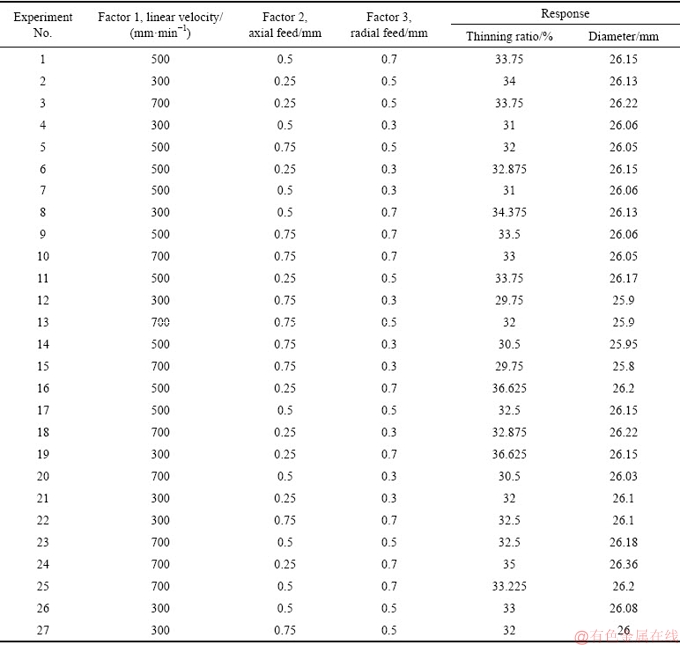
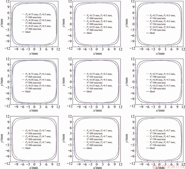
Fig. 9 Comparison between recognized profiles obtained by CMM and ideal profile
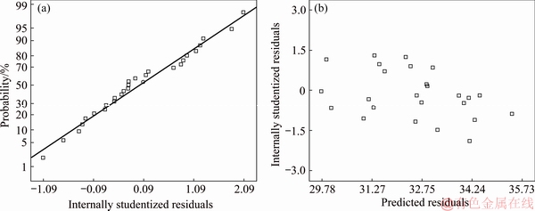
Fig. 10 Distribution of residuals (a) and plot of residuals vs predicted values (b) for thinning ratio
The analysis of variance for the thinning ratio shows that a linear polynomial equation fits the experimental data well. However, the second order terms which have a significant effect on the response (i.e. their p-value <0.05), are added to the model in order to enhance the accuracy of the resulting model. It is worth mentioning that the ANOVA uses three assumptions: (1) normal distribution of the residuals, (2) constant variance, and (3) independent variance. These assumptions should be satisfied in order to guarantee the validity of the results. Thus, Fig. 10(a) shows the plot of the normal distribution of the residuals. It is obvious that experiment data follow the straight line, which means the normal distribution of the residuals is satisfied. On the other hand, the plot of residuals versus predicted values is shown in Fig. 10(b). The random scatter of the points, which has no ordered structure, shows that the model satisfies the assumptions of constant and independent variance. Therefore, the results in this study are accepted and could be utilized to predict the behavior of the process.
Table 4 Analysis of variance for thinning ratio
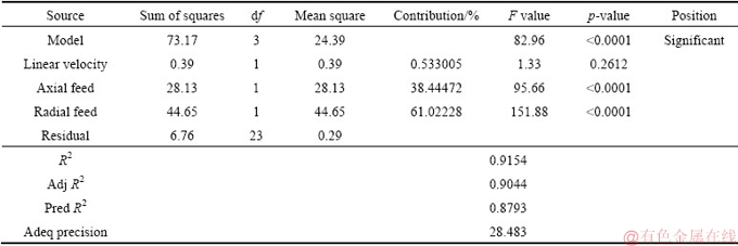
Referring to Table 4, the F-value which is 82.96 shows that the model is significant. In fact, there is only 0.04% chance that the resulting model is influenced by the noises. As well, the model p-value of 0.0001, which is less than 0.05, is another reason of the model being significant. The R2 value should be greater than 0.9, which makes the model valid to be applicable in the experimental range. In the current study, the R2 value is 0.9154 which is satisfied with an appropriate precision. The “Pred R2” should be in a reasonable agreement with the “Adj R2”, within 0.2 of the differences. Here, this value is measured to be 0.0251. Finally, “Adeq precision” value, which measures the signal to noise ratio, should be greater than 4, and in the current model it is equal to 28.483. According to Table 4, radial feed has maximum effect on thinning ratio with 61.02% contribution. On the other hand, linear velocity has minimum effect with 0.53% contribution. Also, there is no interaction between the effects of radial feed, axial feed and linear velocity on thinning ratio.
The graph of predicted versus actual values is illustrated in Fig. 11. The points closer to the line show a more precise prediction of the model.
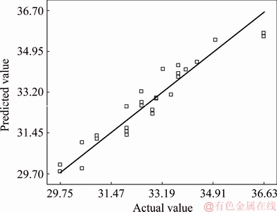
Fig. 11 Graph of predicted vs actual values for thinning ratio
The final regression equation to predict the thinning ratio as a function of process parameters is as follows:
T=31.68426-5Pa+7.875Pr (2)
Regarding to high p-value for linear velocity, this parameter is not significant, and statically has no effect on thinning ratio. Therefore, linear velocity is excluded from the final model.
For the outer cross-section diameter, referring to Table 5, the F-value is 38.93, which shows that the model is significant. In fact, there is only a 0.01% chance that the resulting model is influenced by the noises. Also, the model’s p-value which is less than 0.05 is another evidence for the significant model. The “Adeq precision” value in the current model is equal to 23.373. Among all parameters, axial feed has the maximum effect (with 61.9% contribution) and linear velocity has the minimum effect (with 1.76% contribution) on diameter.
The graph of predicted versus actual values of the determined model is illustrated in Fig. 12. The points closer to the line show a more precise prediction of the model.
The final equation to predict the outer diameter as a function of process parameters is as follows:
Dmax=25.95546+3.94444×10⁻⁴V-0.12833Pa+0.05Pr-0.00111667V・Pa+0.53333Pr・Pa (3)
3.2 Effects of parameters on thinning ratio
The main effects of process parameters on the thinning ratio are shown in Fig. 13. Based on Fig. 13(a), when the linear velocity increases, the thinning ratio decreases. In a quantitative word, when the velocity increases from 300 to 700 mm/min, thinning ratio decreases by 3%. This is because an increase in the velocity hinders the tube walls from a complete deformation and the spring-back reduces the forming magnitude. As a result, the tube tends to return back to its initial shape and the square shape of the tube is reduced (its outer perimeter starts to be reduced). Thus, less thinning is observed at the cross-section corners. Figure 13(b) proves that an increase in the axial feed has a more significant effect on the thinning ratio. An increase in the axial feed means that the distance, at which the forming tool displaces in contact with the tube walls, increases and thus, the greater volume of the material could flow along this movement. As a result, more volume of the material flow in the forming point leads to a less thinning. It is worth mentioning that this causes a non-uniform thickness distribution in the axial direction of the tube. That is, more thickness difference is observed in the regions where the tool is not in contact with the tube. Figure 14 shows the thickness distribution of two different samples, which experience different axial feeds in the direction of forming path. It is obvious that an increase in the axial feed causes the thickness differences to increase. However, the least thickness belongs to the forming condition with the less axial feed. Figure 13(c) confirms that an increase in the radial feed increases the thinning ratio. The higher tensile stresses appear due to the higher radial feeds and as a result, a higher plastic deformation in each forming stage. As a result, the spring-back decreases, and the total plastic strain of the whole process increases, which leads to a higher thinning ratio.
Table 5 Analysis of variance for outer diameter
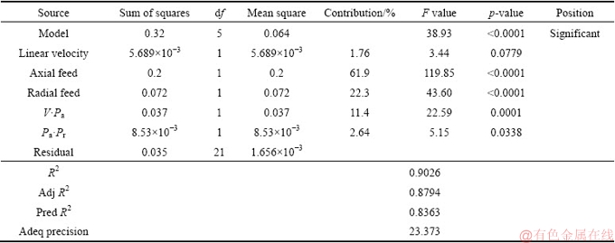
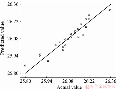
Fig. 12 Graph of predicted vs actual values for outer diameter
3.3 Effects of parameters on outer diameter
The effects of process parameters on the outer diameter of the resulting profile are shown in Fig. 15. As is illustrated in Fig. 15(a), an increase in linear velocity decreases slightly the cross-section diameter. There is a similar reason to what happened in the previous section: an increase in the linear velocity increases the spring-back, decreases the plastic deformation of the tube, and hence, decreases the outer diameter of the profile. Figure 15(b) shows that an increase in the axial feed has a stronger effect on the diameter reduction. Referring to Fig. 16, this is due to an increase in the distance between the forming paths. The spaces between the forming paths (low deformation zone) make disturbance on the forming of the neighboring regions that are in contact with the forming tool. Figure 15(c) shows that by an increase in the radial feed, the outer diameter increases. Again, an increase in the radial feed increases the plastic deformation and decreases the spring-back in the tube. So, a square sectional part with a sharper corner and larger outer diameter is produced.
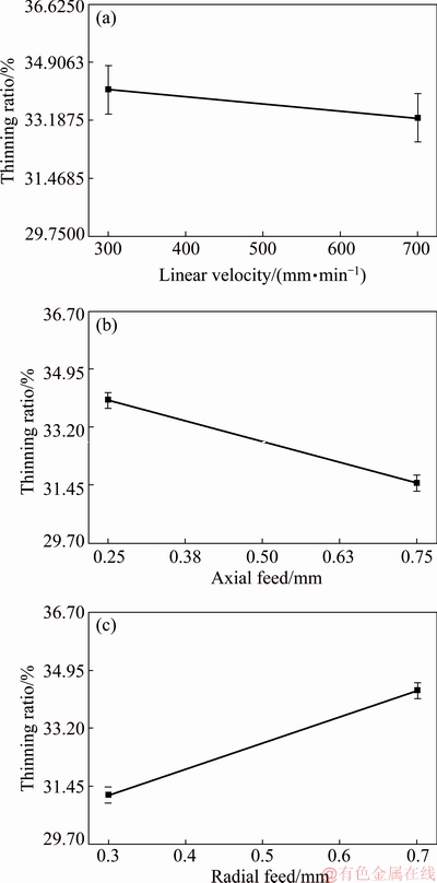
Fig. 13 Influence of linear velocity (a), axial feed (b) and radial feed (c) of tool on thinning ratio
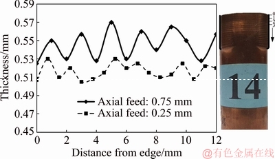
Fig. 14 Thickness distribution of two samples with different axial feeds in direction of forming path
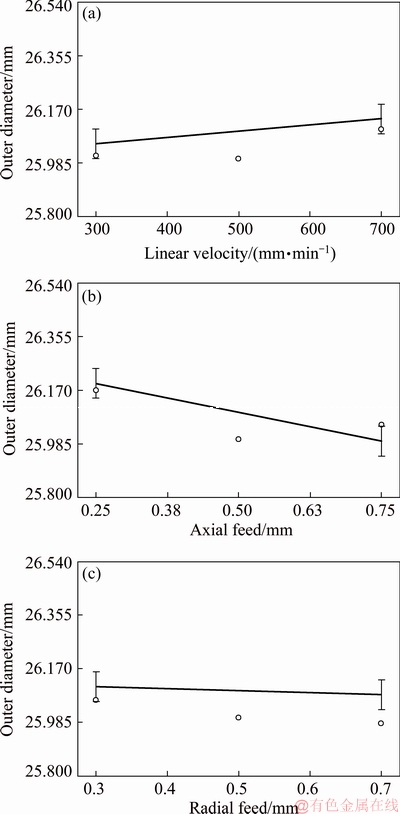
Fig. 15 Influence of linear velocity (a), axial feed (b) and radial feed (c) of tool on outer diameter
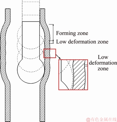
Fig. 16 Forming tool path in forming region
The interactive effect of linear velocity and axial feed on the outer diameter of the profile is shown in Fig. 17(a). It is required to apply the maximum linear velocity and the minimum axial feed, both, to achieve the maximum outer diameter. However, the axial feed has a more significant effect in this regard. The interactive effect of axial feed and radial feed on the outer diameter of the profile is illustrated in Fig. 17(b). It is possible to achieve the maximum outer diameter with applying minimum axial feed and maximum radial feed simultaneously.
4 Conclusions
The single point incremental forming of a thin-walled tube is investigated. The effects of the linear velocity, axial feed and radial feed on the thinning ratio and outer diameter of the product have been studied. Results show that incremental forming process could be a good option to produce square sectional parts with desirable accuracy. Minimum corner radius is achieved when the minimum linear velocity and axial feed, and maximum radial feed are selected. However, in general, the maximum spring-back values are observed in the profile edges, which make some difficulties to reach the ideal profile. An increase in the axial feed decreases the thinning ratio in the tube corners, while an increase in the radial feed leads to an increase in the thinning ratio. This is because less spring-back and more plastic deformation are observed due to an increase in the radial feed. On the other hand, interactive effects of the process parameters show that the maximum linear velocity and axial feed produce the maximum outer diameter of the product. However, the axial feed has a more significant effect in this regard. However, minimum axial feed must be used with maximum radial feed for decreasing the spring-back and as a result increasing the shape conformity.
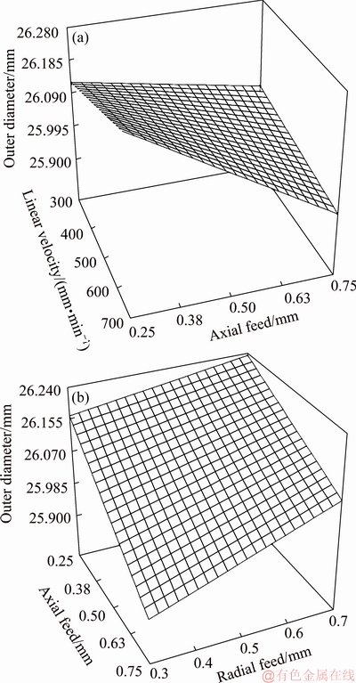
Fig. 17 Interactive effect of linear velocity and axial feed (a) and axial feed and radial feed (b) on outer diameter of resulting profile
References
[1] EMMENS W C, van den BOOGAARD A H. An overview of stabilizing deformation mechanisms in incremental sheet forming [J]. Journal of Materials Processing Technology, 2009, 209: 3688-3695.
[2] JESWIET J, MICARI F, HIRT G, BRAMELY A, DUFLOU J, ALLOWOOD J. Asymmetric single point incremental forming of sheet metal [J]. CIRP Annals-Manufacturing Technology, 2005, 54: 88-114.
[3] MIRNIA M J, MOLLAEI B, VANHOVE H, DUFLOU R. Thickness improvement in single point incremental forming deduced by sequential limit analysis [J]. International Journal of Advanced Manufacturing Technology, 2014, 70: 2029-2041.
[4] SKJOEDT M, SILVA M B, MARTINS P A F, BAY N. Strategies and limits in multi-stage single-point incremental forming [J]. The Journal of Strain Analysis for Engineering Design, 2010, 45: 33-44.
[5] SHI X, HUSSAN G, ZHA G, WU M, KONG F. Study on formability of vertical parts formed by multi-stage incremental forming [J]. International Journal Advance Manufacturing Technology, 2014, 75: 1049-1053.
[6] CRISTINO V A M, MONTANARI L, SILVA M B, MARTINS P A F. Towards square hole-flanging produced by single point incremental forming [J]. Journal of Materials Design and Applications, 2015, 229: 380-388.
[7] LI J C, LI C, ZHOU T. Thickness distribution and mechanical property of sheet metal incremental forming based on numerical simulation [J]. Transactions of Nonferrous Metals Society of China, 2012, 22(S1): s54-s60.
[8] SEYEDKASHI S M H, NAEINI H M, LIAGHAT G H, MASHHADI M M, MIRZAALI M, SHOJAEE K, MOON Y H. The effect of tube dimensions on optimized pressure and force loading paths in tube hydroforming process [J]. Journal of Mechanical Science and Technology, 2012, 26: 1817-1822.
[9] XU Xiang-he, LI Shu-hui, ZHANG Wei-gang, LIN Zhong-qin. Analysis of thickness distribution of square-sectional hydroformed parts [J]. Journal of Materials Processing Technology, 2009, 209: 158-164.
[10] CHOW C L, YANG X J. Bursting for fixed tubular and restrained hydroforming [J]. Journal of Materials Processing Technology, 2002, 130: 107-114.
[11] HASHEMI S J, RAHMANI F. Investigation of the geometry of rectangular cross section aluminum parts in low pressure tube hydroforming process [J]. The Indian Institute of Metals, 2018, 71: 1445-1453.
[12] WEN T, ZHANG S, ZHENG J, HUANG Q, LIU Q. Bi-directional dieless incremental flanging of sheet metals using a bar tool with tapered shoulders [J]. Journal of Materials Processing Technology, 2016, 229: 795-803.
[13] TERAMAE T, MANABE K, UENO K, NAKAMURA K, TALEDA H. Effect of material properties on deformation behavior in incremental tube-burring process using a bar tool [J]. Journal of Materials Processing Technology, 2007, 191: 24-29.
[14] WEN T, YANG C, ZHANG S, LIU L. Characterization of deformation behavior of thin-walled tubes during incremental forming: A study with selected examples [J]. The International Journal of Advanced Manufacturing Technology, 2015, 78: 1769-1780.
[15] MOHAMED F A, EI-ABDEN S Z, ABDEL-RAHMAN M. A rotary flange forming process on the lathe using a ball-shaped tool [J]. Journal of Materials Processing Technology, 2005, 170: 501-508.
[16] YANG C, WEN T, LIU L T, ZHANG S, WANG H. Dieless incremental hole-flanging of thin-walled tube for producing branched tubing [J]. Journal of Materials Processing Technology, 2014, 214: 2461-2467.
[17] HUSSAIN G, VALAEI H, Al-GHAMDI K A, KHAN B. Finite element and experimental analyses of cylindrical hole flanging in incremental forming [J]. Transactions of Nonferrous Metals Society of China, 2016, 26: 2419-2425.
[18] SEYEDKASHI S M H, HASHEMI S J, RAHMANI F. Experimental investigation of effective parameters on a new incremental tube bulging method using rotary tool [J]. International Journal of Advanced Design and Manufacturing Technology, 2017, 10: 83-91.
[19] ASTM E8M. Standard test methods for tension testing of metallic materials [S]. Annual Book of ASTM Standards, Vol 03.01, 2001.
F. RAHMANI1, S. M. H. SEYEDKASHI1, S. J. HASHEMI2
1. Mechanical Engineering Department, University of Birjand, Birjand 97175-376, Iran;
2. Department of Mechanical Engineering, Faculty of Enghelab-e Eslami, Tehran Branch, Technical and Vocational University (TVU), Tehran 13715-173, Iran
摘 要:增量成形是近年来发展起来的一种管材成形工艺。如果能确定工艺参数和最优值的影响,可以优化制造成本和加工精度。将圆形铜管通过增量成形工艺变为方形截面,设计球形成形冲头和管材夹具实验装置。成形冲头的运动由数控机床控制,为了确定刀具线速度、径向进给和轴向进给等工艺参数对方形截面减薄率和最大外径的影响,进行全因子试验设计。结果表明,径向进给对减薄率的影响最大,而轴向进给对最终轮廓的影响最大;径向进给量增大,减薄效果更好;轴向进给量越小,形状一致性越好;而线速度对减薄率没有显著影响。还给出预测响应的回归模型。
关键词:管材增量成形;方形截面;径向进给;轴向进给;减薄
(Edited by Bing YANG)
Corresponding author: S. M. H. SEYEDKASHI; Tel: +98-563-2202133; E-mail: seyedkashi@birjand.ac.ir
DOI: 10.1016/S1003-6326(19)65141-1

