J. Cent. South Univ. Technol. (2011) 18: 1994-2000
DOI: 10.1007/s11771-011-0933-x
Method to determine installing angle of conical point attack pick
LIU Song-yong(������), CUI Xin-xia(����ϼ), DU Chang-long(�ų���), FU Lin(����)
School of Mechanical and Electrical Engineering, China University of Mining and Technology,Xuzhou 221116, China
? Central South University Press and Springer-Verlag Berlin Heidelberg 2011
Abstract: In order to obtain the determining method of the installing angle and decrease the performance indices (cutting force and wearing rate) of the pick, the relationships among the installing angles (impact angle, inclination angle and the skew angle) were studied, and the static model of installing angles of the pick was built. The relationships among the impact angle, the tip angle of pick and the kinematics parameters of the pick were built, too. Moreover, the mechanic models of the maximum clearance angle and the wearing angle of the pick were set up. To research the relationships of the installing angles and the change law of the wearing angle along with the kinematics parameters, the simulation was done. In order to verify the correctness of the models, the cutting experiments were done by employing two picks with different pick tip angles. The results indicate that, the cutting force is the smallest when the direction of the resultant force of pick follows its axis, and the relationship derived among the installing angles should be satisfied. In addition, to decrease the cutting force and the wearing of the pick, the tip angle of pick should not be larger than the half of the difference between the minimum wearing angle and the impact angle of the pick, and the clearance angle must not be less than zero.
Key words: conical point attack pick; cutting force; installing angle; wearing angle; clearance angle
1 Introduction
The conical point attack pick (abbreviated as pick) with the characteristics of cutting rock strongly and effectively was used widely in the area of mining, road construction engineering and underground engineering, etc. For example, the pick was used as the cutter on the cutting mechanisms (shearer drum, roadheader cutting head, cobalt-crust mining head and milling drum and trench cutters, etc). And the efficiency and reliability of the machine were influenced directly by the cutting performance of the pick. Therefore, a lot of researches were done. The linear cutting theory model of the pick was deduced [1] basing on the Coulomb-Moore theory, which indicated that the broken plan of coal follows the Coulomb-Moore��s law. The investigations about the cutting theory of pick were done [2-4], in which the cutting model, the load and the improvement of the cutting efficiency were discussed. Based on the established models of EVANS and NISHIMATSU, the pick cutting theory was analyzed [5-6] and the linear cutting model was built according to the fracture mechanics and the stratification and joint characteristics of the coal, which indicated that the relationship between the cutting force and the cutting thickness is not linear. Effects of equal and unequal circumferential pick spacing on the cutting performance of boom type roadheaders with cylindrical cutting heads were investigated [7], which indicated that no significant difference exists between the performances of the two cutting heads. The finite element analysis and the temperature of the pick cutting rock were studied [8], which indicated that the interfacial temperature of the pick and rock increases linearly along with the cutting speed of the pick. The distribution of the maximum cutting load of pick was studied [9], which was based on the Virtual Prototyping Technology. The relationship between the cutting specific energy of the pick and the rock characteristics was studied [10], which indicated that the cutting specific energy varies linearly with the compressive strength of rock. The cutting experiments of the rocks with different characteristics were done [11-13], which indicated that the cutting performance of the pick is affected mainly by the rock compressive strength and explained the basic rules for governing the relationship between specific energy and chip sizes. The cutting effect of different picks was analyzed by utilizing finite element method [14], from which the relationship between the cutting parameters and the heat was obtained. The multiple linear and nonlinear regression and regression tree methods were utilized in developing the predictive models of the mean cutting force of the pick [15], by which six different empirical models were obtained to predict the mean cutting force of the point-attack pick. Numerical simulation of rock cutting by the point attack pick was studied [16], which pointed out that there was a strong correlation among the modeling, experimental and theoretical studies about the mean peak of the cutting forces.
The cutting theory of the pick was established, but the cutting performance and the cutting efficiency are affected directly by the installing angle of the pick, and the wearing rate of the pick is depended on the installing angle except the material of the pick. Therefore, it is necessary to study the determining method of the installing angle of the pick.
2 Statics model of installing angles
The installing angle of the pick on the cutting mechanism includes impact angle, inclination angle and skew angle. The installing drawing of a pick is shown as Fig.1.
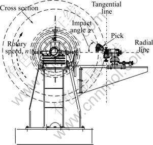
Fig.1 Installation drawing of pick
The impact angle �� is the intersection angle of the axis of the pick and the radial line on the cross section of the cutting mechanism. The cross section of the cutting mechanism is the plane through the pick tip and perpendicular to the axis of the cutting mechanism. The radial line of the cutting mechanism is the line through the pick tip and the center point on the cross section. The tangential line is the line through the tips of pick and perpendicular to the radial line on the cross section of cutting mechanism. The inclination angle ��q,x is the dihedral angle between the tangential rotation plane of the pick and the cross section of the cutting mechanism. The tangential rotation plane is the centerline plane through the axis of the pick and the bottom center line of the pick holder (Fig.2), revolving a certain angle by taking the tangential line as the rotation axis.

Fig.2 Assembly drawing of pick
The skew angle ��w,x is the dihedral angle between the radial rotation plane of the pick and the cross section of the cutting mechanism. The radial rotation plane is the centerline plane revolving a certain angle by taking the radial line of cutting mechanism as the axis of revolution. The location of pick is depended on the tip of pick in the manufacture process of the cutting mechanism, and the installing angles of a pick are varied with the position of pick on the cutting mechanism.
In order to obtain the relationship among the install angles, the mechanical model of a pick with arbitrary angle is built, as shown in Fig.3 and Fig.4, and the hypothesis is done as follows:
1) The pick, the pick holder and the cutting mechanism are processed as a rigid unit;
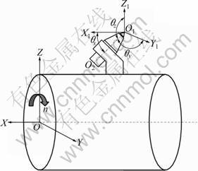
Fig.3 Install angles of pick

Fig.4 Diagram of pick forces
2) The pick load is simplified as concentrated force acting on the pick tip.
As shown in Fig.3, the global coordinate is established on the cutting mechanism. O is the center of the lateral face of the cutting mechanism, X axis is along the cutting mechanism axis, Y axis is along the advance direction of the cutting mechanism, and Z axis is upward. The local coordinate O1X1Y1Z1 is built on the tip of pick with the same orientation as the global coordinate. In Fig.3, ��x, ��y and ��z are the intersection angle between the axis O1O2 of the pick and the coordinate axis X1, Y1 and Z1. To express the three-dimensional cutting force of the pick expediently, the pick is represented by O1O2 in Fig.4. xi, yi and zi are used to express the lateral force, the advancing force and the cutting force, respectively. These three forces are perpendicular to each other.
The cutting efficiency is the best and the wearing is the smallest when the resultant force of the pick is along its axis. Therefore, the direction of the resultant force is assumed along the axis O1O2 of the pick, and xi is perpendicular to the resultant force of yi and zi. The cutting force zi is perpendicular to the gyration radius O1O3 of the tip of pick, which is along the tangential line of the gyration circle in the plane Y1O1Z1; yi follows the direction of the gyration radius O1O3.
Besides the angles defined in Figs.3 and 4, the pick load is also affected by the setting angle �� and the position angle ��i. The angle ��i is the intersection angle of the radius line of pick and the coordinate axis Z. The angle �� is the intersection angle of the axis and the tangential line of the pick on the cross section, which is the complementary angle of the impact angle, ��=��/2-��, as shown in Fig.5. vq is the advancing speed, m/min; n is the revolving speed, r/min.
To obtain the relationship among ��, ��q,x and ��w,x, the relation model among them is built, as shown in Fig.6.
O1B is used to express the direction of cutting force zi, O1O3 is used to express the direction of advancing force yi, and xi is along O1X1. The projection of the point O2 on the pick axis O1O2 is done, and the intersection point A is acquired in the plane AO1O3, and the point A is connected with the point O1. The line AB is perpendicular to BO1, and the point B is connected with the point O2. The line O1B is perpendicular to the line O2B because the line O2A is perpendicular to the line O1B, therefore, the angle ��ABO2 is the dihedral angle of the plane O1O2B and the plane AO1B, namely the inclination angle ��q,x. The line AC is constructed perpendicular to the line O1O3 through the point A, and point O2 is connected with the point C. Because the line O2A is perpendicular to the line O1C, ��ACO2 is the dihedral angle of the plane ABO1C and plane O2O1C, namely the skew angle of pick ��w,x. Simultaneously, ��AO1C is the impact angle �� according to the definition of the impact angle of pick. And ��O2O1C=��z according to Fig.3 and Fig.6.
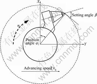
Fig.5 Position of pick on cutting mechanism
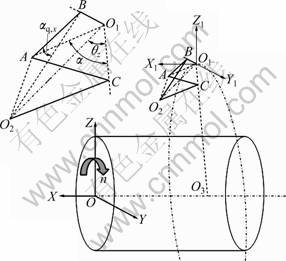
Fig.6 Relation of pick angles
Based on the relationship built above, assuming that the pick length is Lj, the mathematic model of the installing angles can be acquired according to the trigonometric function as
 (1)
(1)
 (2)
(2)
 (3)
(3)
where �� is the impact angle, rad; Lj is the pick length, m; ��z is the intersection angle of the pick axis and the coordinate Z1, rad.
According to Eq.(1)-Eq.(3), there is
 (4)
(4)
 (5)
(5)
where  is the skew angle, rad.
According to the Pythagorean theorem and Eqs.(4) and (5), there is

 (6)
(6)
 (7)
(7)
where ��q,x is the inclination angle, rad.
The relationship among the installing angles is acquired according to Eq.(5) and Eq.(7) as

 (8)
(8)
According to the above analysis, in order to make the resultant force of the pick along its axis, the installing angles should be satisfied with Eq.(8) when the cutting mechanism is designed, for improving the cutting efficiency and service life of the pick.
3 Kinematics model of installing angles
The cutting load, the cutting specific energy and the wearing of the pick are influenced directly by the kinematics parameters of the pick. In addition, the installing angles are influenced by the kinematics parameters of the pick, too. So, the analysis of the installing angle of pick affected by the kinematics parameters is done. To make the rock broken continuously, the picks must be moved along a line except for the revolving motion with the cutting mechanism. The structure of the pick is shown in Fig.7.

Fig.7 Structure of pick
The motion of a pick is shown in Fig.8. The point M is the initial position of an arbitrarily pick, the point M1 is the position to which the pick moves for a time t, and the coordinate of the cutting mechanism is changed from the coordinate xOy to the coordinate xO4y��. ��jj is the intersection angle of the pick tip. The kinematics formula is acquired according to Fig.8:
 (9)
(9)
where R is the radius of the cutting mechanism, m; ��z is the revolved angle of the pick, rad; t is the revolving time, s; n is the revolving speed, r/min.

Fig.8 Kinematics diagram of pick
The instantaneous centre of the pick is the same with the cutting mechanism because they are processed as a rigid unit when the pick moves with the cutting mechanism. And it can be seen from Fig.9 that, the velocity direction of the pick on the point M should be the direction of the resultant velocity v. The line O��M goes through the point M and is perpendicular to the velocity v. And the velocity direction of the pick on the point M1 follows the direction of the velocity v1, the vertical line of the velocity v1 is constructed and meets the coordinate y at the point O��, and the point O�� and the point M are connected. So, the point O�� is the instantaneous centre of the pick on the point M according to the theoretical mechanics. Based on this, it can be known that the pick velocity on the point M is larger than the velocity on the point M1, which indicates that the pick velocity is not equal on the different positions of the cutting mechanism. Therefore, in the process of the pick cutting rock, the actual tangential line GH of the pick is different with the tangential line EF of the cutting mechanism. So, the clearance angle �� (��GMD) is generated between the pick back and the cutting surface, as shown in Fig.10.
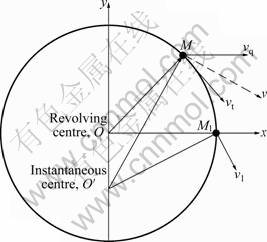
Fig.9 Instantaneous centre of pick (vt��Tangential speed, m/min; v1��Instantaneous speed, m/min; v��Resultant speed, m/min)

Fig.10 Clearance angle and wearing angle
According to Fig.10 and the definition of the impact angle, the interference between the pick body and the rock will happen if the sum (��+��jj/2) of the angle �� and the half of the angle ��jj is larger than the wearing angle ��. So, the condition (��+��jj/2)�ܦ� should be satisfied when the pick is designed. The computation formula of �� is acquired according to the relationships among the angles in Fig.10 as
 (10)
(10)
To obtain the minima of the angle ��, the angle ��MOO��=��/2 should be satisfied. So, there is
 (11)
(11)
Eq.(10) is substituted into Eq.(11), and Eq.(12) is obtained:
 (12)
(12)
According to Eq.(10), �� is ��/2 when the angle ��MOO��=0. The boundary of the intersection angle on the pick tip and the maxima of the working clearance angle can be acquired according to the formula vt=��nR/30 and the condition (��+��jj/2)�ܦ�:
 (13)
(13)
To decrease the wearing and improve the load state of the pick, the pick angle should be satisfied with Eq.(13) when the pick is designed or selected.
4 Simulation and experiment analysis
To research the relationships among the installing angles and the change law of the structure parameters of the pick, the simulation was done. According to the actual conditions, the range of the impact angle was 2��/9-��/3; the range of the skew angle was 0-��/18; the range of the revolving speed was 40-60 r/min; the advancing speed was 0-10 m/min. The results are shown in Fig.11 and Fig.12.
It can be seen that, the inclination angle increases along with the increase of the impact angle, and it decreases along with the increase of the skew angle. So, if the impact angle and the skew angle are determined, the inclination angle should be satisfied with Eq.(8) or Fig.11 to make the resultant force direction of the pick along its axis. Simultaneously, the wearing angle �� increases along with the increase of the revolving speed of pick, and decreases along with the increase of the advancing speed. So, the intersection angle ��jj of the pick tip depends on the kinematics parameters of the pick when the pick is designed or manufactured. And the angle ��jj increases along with the increase of the angle ��, and decreases along with the increase of the impact angle. Simultaneously, the angle �á�0 should be satisfied to decrease the wearing of the pick.

Fig.11 Relations among installing angles
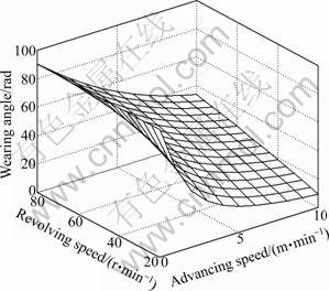
Fig.12 Change law of wearing angle
To verify the correctness of Eq.(13), the experiment was done on the Cutting Test-bed for Rock & Coal [17]. Experiment conditions were: the advancing speed of pick was 1.0 m/min, the revolving speed was 60 r/min, the compressive strength of the cut material was 1.43 MPa, the impact angle was 2��/9, and the radium of the cutting mechanism was 0.27 m. So, the angle �� should be 11��/30, and the angle ��jj should be 13��/45. Based on these, the two different picks (��jj=5��/18 and ��jj=��/3) were designed for the experiment. The cutting load of them is shown in Fig.13.
It can be seen that the cutting load of the pick with the tip angle ��jj=��/3 is larger than that of the pick with the tip angle ��jj=5��/18, which indicates that the angle ��jj should be closed to the angle got from Eq.(13); otherwise, the cutting load and the wearing of the pick will increase. So, Eq.(13) should be satisfied when the pick is designed or selected.

Fig.13 Cutting load of picks
5 Conclusions
1) In order to make the direction of the resultant force of pick follow its axis and improve the cutting efficiency and decrease the cutting force, the relationship model:

among the impact angle ��, the skew angle ��w,x and the inclination angle ��q,x should be satisfied when the pick is installed.
2) The range of the tip angle of pick is obtained as ��jj��2��min-2��, and the theory model of the maximum clearance angle, ��max=��max-��-��jj��0, is built by analyzing the kinematics parameters of pick. The wearing and cutting load of the pick will decrease if the pick is designed or selected according to these models.
References
[1] NISHIMATSU Y. The mechanics of rock cutting [J]. International Journal of Rock Mechanics and Mining Sciences, 1972, 9(2): 261- 270.
[2] EVANS I. The force required to cut coal with blunt wedges [J]. International Journal of Rock Mechanics and Mining Sciences & Geomechanics Abstracts, 1965, 2(1): 1-12.
[3] EVANS I. Line spacing of picks for effective cutting [J]. International Journal of Rock Mechanics and Mining Sciences & Geomechanics Abstracts, 1972, 9(3): 355-361.
[4] EVANS I. A theory of the cutting force for point-attack picks [J]. International Journal of Rock Mechanics and Mining Sciences, 1984, 2(1): 67-71.
[5] NIU Dong-min. Study of coal cutting mechanism of cutting tools [J]. Journal of China Coal Society, 1993, 18(5): 49-54. (in Chinese)
[6] NIU Dong-min. Mechanical model of coal cutting [J]. Journal of China Coal Society, 1994, 19(5): 526-529. (in Chinese)
[7] EYYUBOGLU E M, NACI B. Effects of circumferential pick spacing on boom type roadheader cutting head performance [J]. Tunnelling and Underground Space Technology, 2005, 20(5): 418- 425.
[8] JOHN P L, KAEANAM U M R. Heat transfer simulation in drag-pick cutting of rocks [J]. Tunnelling and Underground Space Technology, 2005, 20(3): 263-270.
[9] XIA Yi-min, BU Ying-yong, MA Zhi-guo, ZHAO Hai-ming, LUO Bo-wen. Modeling and simulation of ocean mining subsystem based on virtual prototyping technology [J]. Journal of Central South University of Technology, 2005, 12(2): 176-180.
[10] TIRYAKI B, DIKMEN A C. Effects of rock properties on specific cutting energy in linear cutting of sandstones by picks [J]. Rock Mechanics and Rock Engineering, 2006, 39(2): 89-120.
[11] BILGIN N, DEMIRCM M A, COPUR H, BALCIA C, TUNCDEMIRA H, AKCIN N. Dominant rock properties affecting the performance of conical picks and the comparison of some experimental and theoretical results [J]. International Journal of Rock Mechanics and Mining Sciences, 2006, 43(1): 139-156.
[12] BALCI C, BILGIN N. Correlative study of linear small and full-scale rock cutting tests to select mechanized excavation machines [J]. International Journal of Rock Mechanics and Mining Sciences, 2007, 44(3): 468-476.
[13] TUNCDEMIR H., BILGIN N, COPUR H, BALCI C. Control of rock cutting efficiency by muck size [J]. International Journal of Rock Mechanics and Mining Sciences, 2008, 45(2): 278-288.
[14] BRIJES M. Analysis of cutting parameters and heat generation on bits of a continuous miner�Cusing numerical and experimental approach [D]. USA: College of Engineering and Mineral Resources at West Virginia University, 2007.
[15] TIRYAKI B, BOLAND J N, LI X S. Empirical models to predict mean cutting forces on point-attack pick cutters [J]. International Journal of Rock Mechanics and Mining Sciences, 2010, 47(5): 858- 864.
[16] SU O, NURI A A. Numerical simulation of rock cutting using the discrete element method [J]. International Journal of Rock Mechanics and Mining Sciences, 2011, 48(3): 434-442.
[17] LIU Song-yong, DU Chang-long, CUI Xin-xia. Research on the cutting force of a pick [J]. Mining Science and Technology, 2009, 19(4): 514-517.
(Edited by YANG Bing)
Foundation item: Project(51005232) supported by the National Natural Science Foundation of China; Project(20100481176) supported by the China Postdoctoral Science Foundation; Project(201104583) supported by the China Postdoctoral Special Fund; Project(1101106c) supported by Jiangsu Postdoctoral Foundation, China
Received date: 2010-11-18; Accepted date: 2011-01-14
Corresponding author: LIU Song-yong, PhD; Tel: +86-13912033086; E-mail: liusongyong@cumt.edu.cn

