Modeling bidirectional reflection distribution function ofmicroscale random rough surfaces
来源期刊:中南大学学报(英文版)2010年第2期
论文作者:王爱华 HSU P. F. 蔡九菊
文章页码:228 - 234
Key words:bidirectional reflection distribution function; random rough surfaces; Maxwell equations; finite difference time domain method
Abstract: The radiative properties of three different materials surfaces with one-dimensional microscale random roughness were obtained with the finite difference time domain method (FDTD) and near-to-far-field transformation. The surface height conforms to the Gaussian probability density function distribution. Various computational modeling issues that affect the accuracy of the predicted properties were discussed. The results show that, for perfect electric conductor (PEC) surfaces, as the surface roughness increases, the magnitude of the spike reduces and eventually the spike disappears, and also as the ratio of root mean square roughness to the surface correlation distance increases, the retroreflection becomes evident. The predicted values of FDTD solutions are in good agreement with the ray tracing and integral equation solutions. The overall trend of bidirectional reflection distribution function (BRDF) of PEC surfaces and silicon surfaces is the same, but the silicon’s is much less than the former’s. The BRDF difference from two polarization modes for the gold surfaces is little for smaller wavelength, but it is much larger for the longer wavelength and the FDTD simulation results agree well with the measured data. In terms of PEC surfaces, as the incident angle increases, the reflectivity becomes more specular.
基金信息:the National High-Tech Research and Development Program of China
J. Cent. South Univ. Technol. (2010) 17: 228-234
DOI: 10.1007/s11771-010-0035-1 ![]()
WANG Ai-hua(王爱华)1, 2, HSU P. F.2, CAI Jiu-ju(蔡九菊)1
1. School of Materials and Metallurgy, Northeastern University, Shenyang 110819, China;
2. Department of Mechanical and Aerospace Engineering, Florida Institute of Technology,
Melbourne 32901, USA
? Central South University Press and Springer-Verlag Berlin Heidelberg 2010
Abstract: The radiative properties of three different materials surfaces with one-dimensional microscale random roughness were obtained with the finite difference time domain method (FDTD) and near-to-far-field transformation. The surface height conforms to the Gaussian probability density function distribution. Various computational modeling issues that affect the accuracy of the predicted properties were discussed. The results show that, for perfect electric conductor (PEC) surfaces, as the surface roughness increases, the magnitude of the spike reduces and eventually the spike disappears, and also as the ratio of root mean square roughness to the surface correlation distance increases, the retroreflection becomes evident. The predicted values of FDTD solutions are in good agreement with the ray tracing and integral equation solutions. The overall trend of bidirectional reflection distribution function (BRDF) of PEC surfaces and silicon surfaces is the same, but the silicon’s is much less than the former’s. The BRDF difference from two polarization modes for the gold surfaces is little for smaller wavelength, but it is much larger for the longer wavelength and the FDTD simulation results agree well with the measured data. In terms of PEC surfaces, as the incident angle increases, the reflectivity becomes more specular.
Key words: bidirectional reflection distribution function; random rough surfaces; Maxwell equations; finite difference time domain method
1 Introduction
Electromagnetic wave scattering by random rough surfaces presents great theoretical challenges due to the large degrees of freedom in these systems and the need to include multiple scattering effects accurately. Scattering from patterned or random rough surfaces and coatings is of fundamental and practical interest to many disciplines, e.g., remote sensing, surface optics, thermal control and wafer thermal processing [1]. In the past three decades, considerable experimental and theoretical progress has been made in understanding the scattering process involved in such problems. KNOTTS and O’DONELL [2] measured the coherent and incoherent component of the polarized intensities scattered from a set of one- dimensional Gaussian rough gold surfaces. SHEN et al [3], and FENG and WEI [4] developed scatterometers that can measure the bidirectional reflectance and transmittance of semiconductor wafer and the polarized bidirectional reflectivity of painted surfaces. LEE et al [5] modeled the directional radiative properties of rough silicon and gold surfaces. Rapid advances in computer modeling allow us to solve the Maxwell’s equations exactly without the limitations of analytical approximations, for example, the Kirchhoff approximation and small perturbation theory, whose regimes of validity are often difficult to assess [6].
Several theoretical treatments were developed to understand light scattering from very rough surfaces, for example, the ray tracing method [7], and the integral equation method. Due to difficulties in computing higher-order terms and in the solution convergence, perturbation series has been limited to weakly rough surfaces. Geometric ray tracing is limited to roughness being larger than the incident wavelength, so the wave interference effect can be neglected. A numerical scheme was used to solve the Maxwell electromagnetic (EM) equations and to examine the wave interference effects on the surface reflectivity without the simplifications assumed in the ray tracing and other methods. This solution scheme is the finite difference time domain (FDTD) method. The FDTD method is conceptually simple and systematic and can integrate with other physical processes, e.g., heat transfer, readily [8]. The time stepping scheme is explicit but can be improved with implicit time stepping to go beyond the Courant-Friedrichs-Lewy (CFL) limit [9]. In this work, a conventional FDTD scheme with perfectly matching layer boundary was used [10].
The bidirectional reflectivity or bidirectional reflection distribution function (BRDF) is of the particular interest in this work. The surfaces used in this work were one-directional, i.e., the surface height (ζ) is a function of one spatial coordinate ζ=f(x). The surfaces under consideration have 1D random rough structure. The surface slopes are represented by jagged edges of the discretized rectangular volume elements. The element size needs to be less than the incident wavelength. The simulation time step size also needs to be controlled according to the CFL criterion, which is necessary for the explicit scheme. Several other factors impacting modeling accuracy were also considered. Finally, the predicted properties of a perfectly electric conductor, silicon and gold surfaces were discussed.
2 Theoretical fundamentals
2.1 One-dimensional random rough surface
In this work, the random rough surface is considered to be homogeneous and isotropic. If the surface height conforms to a normal (Gaussian) distribution, it will follow a probability density distribution shown as follows:
![]() (1)
(1)
where δ is the standard deviation. In this distribution, the mean value of z ?is equal to 0 and δ is the root mean square (RMS) roughness of a surface. Large δ value corresponds to large roughness. It is noted that Eq.(1) does not contain the correlation distance, but in a real surface the height at any position in the rough surface is correlated with the heights of the adjacent points.
To generate a random surface, a specific form of the correlation function has to be used. The Gaussian correlation function given below was used:
![]() (2)
(2)
where T is the distance between the two points. Correlation distance τ is defined in such a way that C(τ)= exp-1. If the surface topographic or height data is available, the C(T) function can be evaluated from the data. Furthermore, due to the surface anisotropy, the actual correlation function may depend on the direction of T (position vector) or azimuthal angle as shown in Ref.[11].
2.2 Finite difference time domain method
The FDTD method allows one to understand the scattering process and compare with the experimental measurements with few assumptions typically used in the analytical models. Maxwell equations take the following form for a linear isotropic material:
![]() ×
×![]() (3)
(3)
![]() ×
×![]() (4)
(4)
where E and H represent the electric and magnetic fields, respectively; Js and Ms are the electrical and magnetic field sources; ε, μ, σ, and σ* are the permittivity, permeability, electrical conductivity, and magnetic conductivity or equivalent magnetic loss of the material, respectively. In the current problem, Js and Ms are zero. To demonstrate the application of Maxwell equations in the surface rough geometry, a two-dimensional formulation is discussed. The 2D structure is assumed to be extended infinitely in the z-direction so that all physical parameters and electromagnetic field are functions of x- and y-coordinates only. Maxwell equations can be decomposed into two independent sets of equations: the transverse electric (TE) polarization and the transverse magnetic (TM) polarization. By replacing the electric and magnetic fields with their vector components, the 2D TE set of equations is:
![]() (5a)
(5a)
![]() (5b)
(5b)
![]() (5c)
(5c)
The 2D TM set of equations is similarly obtained for Hz, Ex, and Ey. Eqs.(5a)-(5c) are expressed in the finite difference time domain equations based on the mesh shown in Fig.1 [8]. The FDTD solution procedure of Eq.(5) is straightforward. However, several issues with FDTD need to be considered: (1) special treatment of boundary condition is required to avoid mixing the reflected wave from the artificial computational domain boundary with the forward and backward (or reflected) propagation waves. For the appropriate boundary surfaces, it is necessary to add the “perfectly matched layer” (PML) as the boundary condition [12]; (2) FDTD is not convenient to handle curved geometry; and (3) to avoid checkerboard pattern in the solution, the staggered grid is used [13], i.e., E and H components are not solved at the same node points (Fig.1). An alternative scheme will be the high order upwind scheme with finite volume mesh [14]. This can handle arbitrary geometry and avoid dispersion and diffusion errors usually associated with the hyperbolic wave equations. As shown in Fig.1, E and H are spatially shifted by 1/2 space increment, and the calculated results of them are temporally shifted by 1/2 time increment, so, all unknown variables at any time step can be calculated based on the variables at the previous half-and full-time step status. The Maxwell equations of Eq.(5) in 2D are not repeated here.
If the interface of different materials is parallel to one of coordinate axes, e.g., Eq.(5) applies to reflection from an interface plane parallel to z-axis in Fig.1, continuity of tangential E and H is naturally maintained; the algorithm itself is divergence-free in the absence of electric and magnetic charge; the time-stepping algorithm is nondissipative, which means that EM wave propagating within the mesh will not decay due to the algorithm itself. All these make Yee’s algorithm a robust method in solving EM field issues.

Fig.1 Discretization and field vector components used in FDTD analysis
Fig.2 illustrates the geometry and computational zone in the FDTD solution of the random rough surface scattering problem. The computational zone is divided into scattering field (SF) and total field (TF) by a virtual plane, at which a plane incident wave into the TF region is initiated at t=0 as the radiation source. In the SF, the E and H components in calculation belong only to the scattered wave, but in TF region, they include contributions from both scattered wave and incident wave. The whole region is surrounded by two PML (top and bottom) and two periodic boundary conditions on the left and right sides.
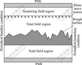
Fig.2 Computation zones and boundary conditions used in EM wave reflection calculation from random rough surface
The FDTD method calculates the transient electromagnetic fields throughout the computational domain under the excitation of a monochromatic harmonic field. The interesting results in this study are the radiative properties. These are associated with the electromagnetic fields through the intensity of the harmonic wave. The reflectivity is defined as the ratio of the reflected intensity to the incident intensity and the transmissivity is defined as the ratio of the transmitted intensity to the incident intensity. For the TE polarization, the reflectivity Re is calculated at the far field (see below on the near-to-far-field (NTFF) transformation) above
the rough surface and has the following form:
 (6)
(6)
where the incident electric and magnetic fields Ein and Hin are input, and E and H are obtained from the FDTD solution and far field transformation. Other properties can be found similarly or using the energy balance relation. The relations given above are wavelength- dependent. It is straightforward to obtain wavelength- integrated or total property.
2.3 Near-to-far-field transformation
E and H components obtained from FDTD solution are near field quantities. These need to be transformed to far field values related to the observable, macro-scale properties, e.g., Eq.(6). The transformation is based on the harmonic property of EM wave equations, with which Green’s theorem is applied [8]. The NTFF transformation yields the far field EM results from near field values on a selected virtual contour in SF region. The contour encloses the random rough surface. To apply NTFF transformation, the scalar values of EM field need to be converted into complex form by Fourier transformation. The complex value contains both the amplitude and phase information. Assume that V is the complex form (E or H), and v(t) is its time-dependent scalar value, i.e., ![]() where ω is the angular velocity and
where ω is the angular velocity and ![]() is the phase. Thus, Fourier transform of v(t) is:
is the phase. Thus, Fourier transform of v(t) is:
![]()
![]()
![]()
![]() (7)
(7)
where D is the period, and |V| and ![]() can be easily calculated using this equation with the given v(t). With the complex form of
can be easily calculated using this equation with the given v(t). With the complex form of ![]() the far-field
the far-field ![]() can be calculated by
can be calculated by
![]()
![]()
![]() (8)
(8)
where ![]() is a unit vector in the z-direction;
is a unit vector in the z-direction; ![]() is a unit vector normal to the integral contour Ca;
is a unit vector normal to the integral contour Ca; ![]() is a position vector on C';
is a position vector on C'; ![]() is a unit vector pointing to the far-field position, and
is a unit vector pointing to the far-field position, and ![]() is the far-field position vector. Ca is an arbitrary shape curve and, in this case, can be assigned a rectangle that encloses the scattered field.
is the far-field position vector. Ca is an arbitrary shape curve and, in this case, can be assigned a rectangle that encloses the scattered field.
3 Results and discussion
The calculations using 60 surfaces with each surface length equal to 50λ were taken to model BRDFs of different materials. Various parameters that influence modeling accuracy were also analyzed: the numerical dispersion, mesh size and number of time steps for steady state results. Finally, BRDFs of four perfect electric conductor (PEC) surfaces with various degrees of roughness were compared with those obtained by ray tracing and integral equation solutions of Maxwell equations. The BRDFs of silicon and gold surfaces were also given. The effect of large incident angle was discussed.
3.1 Numerical dispersion
The apparent characteristics of numerical dispersion are: (1) the phase velocity of numerical wave differs from that of the physical propagating wave, and the amount of difference varies with wavelength, direction of propagation, and discretization, (2) non-physical results, for example, a pseudo-reflection on the underside of a perfectly reflective surface, and (3) imprecise superstition of multiple scattered waves. The numerical phase velocity propagating in vacuum along grid axes and that along grid diagonals can be derived as [8]:
 (9)
(9)
 (10)
(10)
where Nλ=λ/(n?η), S=c?t/(n?η), ?η is the grid interval, ?t is the time step, n is the medium’s refractive index, and S is the well-known CFL criterion. From the above relations, the numerical phase velocity approaches to physical light speed when Nλ→∞, which means infinitely small mesh size. Furthermore, to maintain the stability of FDTD algorithm, S<1 is required for 1D calculations. Similarly, S<![]() for 2D calculations is needed. When the interference phenomenon is strong, the numerical dispersion may impact the final results significantly, especially when the wave goes through a long distance without dissipation.
for 2D calculations is needed. When the interference phenomenon is strong, the numerical dispersion may impact the final results significantly, especially when the wave goes through a long distance without dissipation.
In the current problem, the phase error is not likely to be an issue when the coherence of reflected waves is very weak due to the random roughness. If the RMS roughness is not very large in comparison with the incident wavelength and there is a certain degree of partial coherence, then the dispersion may become important. Although the current code does not correct the phase velocity induced dispersion error, it is determined that the effect on the random rough surface calculation is minimal with reduced mesh size and is acceptable for the current problem.
3.2 Other relevant factors
(1) Mesh size. The mesh size has the primary effect on the solution accuracy of the spatial central difference scheme. It also affects the magnitude of the dispersion error discussed above. In this work, λ/20 mesh size was considered sufficient and used for random rough surface reflection calculation, unless specified otherwise.
(2) Number of time steps. Generally speaking, the longer the physical path length traveled by the wave, the more the time steps needed to ensure sufficient time for all the scattered waves to interact and reach steady state results. In practice, several different time steps are used in FDTD computation on a rough surface and then the results are compared to determine the minimum required time steps.
(3) Surface size. It is clear that a rough surface will require a longer surface length to produce equally accurate results in comparison with that of a smoother surface. For the problem of interest, the surface length is 3 000λ and the 60×50λ surfaces were used in the calculations. Even the calculation of the 60×50λ surfaces is the most economical in terms of computation time and solution accuracy, it still took run time of about 10 h.
3.3 Scattering from random rough surfaces
The bidirectional reflection distribution functions
(simplified as fBRDF) of four PEC Gaussian surfaces with various degrees of roughness are shown in Fig.3. Fig.3(a) shows that with the slightly rough surface the fBRDF of FDTD solution is somehow smaller than that of the integral equation solution. However, in the specular direction, θobs=30?, there is a sharp spike that is not seen in the other two solutions. As the surface roughness increases, the magnitude of the spike reduces and eventually the spike disappears in the case of δ/τ≥0.75. This behavior seems to be physically reasonable. Also, as δ/τ increases, the retro-reflection becomes evident (see Fig.3(b)). In Fig.3(c), the agreement between EM integral equation solution and ray tracing is better than that between FDTD and ray tracing solutions. The retro-reflection peak, although small, is evident in FDTD solution. Due to the relative shorter surface length versus the correlation length δ/τ in this case, the FDTD solution exhibits larger oscillations than those in other cases. To ensure that there is a retro-reflection peak at θobs=-30? and not simply a large oscillation occurring coincidently at that angle, twice of the surface length was used in the FDTD calculation (results not shown) and confirmed the retro-reflection peak. The integral equation solution has smaller oscillations in this case and a small peak at θobs= -30?, in comparison with FDTD results. At δ/τ=1.1 (Fig.3(d)) the ray tracing starts to show retro-reflection peak, although it is still smaller than those in the EM solutions.

Fig.3 Comparison of FDTD results with those obtained from ray tracing and integral equation methods under different PEC surface roughnesses: (a) δ/τ=0.20, δ/λ=0.2, τ/λ=1.0, θi=30?; (b) δ/τ=0.50, δ/λ=0.3, τ/λ=0.6, θi=30?; (c) δ/τ=0.75, δ/λ=7.5, τ/λ=10, θi=30?; (d) δ/τ=1.1, δ/λ=1.1, τ/λ=1.0, θi=30?
Two different surface materials were examined: PEC and silicon, which have refractive index n=3.426. As shown in Fig.4, the overall trend of fBRDF is the same, especially the specular spike. The silicon surface has two polarizations with TE mode reflectivity being higher than that of the TM mode. The silicon’s fBRDF is about 1/3 of the PEC’s value due to the transmission into the material.

Fig.4 BRDF comparison of PEC and silicon surfaces: (a) δ/τ=0.2, δ/λ=0.2, τ/λ=1.0, θi=30?; (b) δ/τ=0.5, δ/λ=0.3, τ/λ=0.6, θi=30?
Fig.5 depicts fBRDF of two incident wavelengths at θi=30? in TE and TM modes. At a smaller wavelength of 1.152 μm, there is little difference between the two modes. On the other hand, at 3.392 μm fBRDF in TM mode is clearly smaller than that in TE mode for 0?< θobs<50?, i.e., angles near the specular direction.
In Fig.6, the fBRDF of gold surface under two different wavelengths at θi=30? was shown. Overall, at a moderate incident angle, the agreement between the FDTD simulation and measured data is good. However, as expected, the agreement is better at large wavelength (3.392 μm) than that at smaller wavelength (1.152 μm). In the latter case, if the longer total surface length were used, the FDTD solution oscillations near the specular reflection direction would reduce. However, this seems to be redundant at this point. Since the σ/λ is smaller at a large wavelength, the specular or coherent component is stronger at λ=3.392 μm.
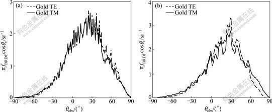
Fig.5 BRDF at two different incident wavelengths of gold surface: (a) δ/τ=0.2, δ/λ=0.5, τ/λ=2.5, θi=30?, incident wavelength 1.152 μm; (b) δ/τ=0.2, δ/λ=0.2, τ/λ=1.0, θi=30?, incident wavelength 3.392 μm
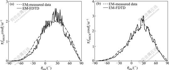
Fig.6 Comparison of FDTD results with measured data [2] for gold surface under different wavelengths: (a) δ/τ=0.2, δ/λ=0.5, τ/λ=2.5, θi=30?, incident wavelength 1.152 μm; (b) δ/τ=0.2, δ/λ=0.2, τ/λ=1.0, θi=30?, incident wavelength 3.392 μm
Fig.7 shows the effect of large incident angle on fBRDF for a PEC surface. As the incident angle increases, fBRDF becomes more specular. The large incident angle would effectively reduce the roughness. Thus, there is the appearance of specular spike in the PEC surface of Fig.7. A well-known phenomenon of large incident angle is the off-specular peak described by TORRANCE and SPARROW [15]. An attempt was made to reproduce the off-specular peak with dielectric surface but was not successful since the surface roughness description was incomplete in the original paper, in which only the RMS roughness was given [15].
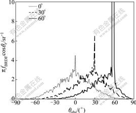
Fig.7 BRDF at three different incident angles of PEC surface (δ/τ=0.2, δ/λ=0.2, τ/λ=1.0)
4 Conclusions
(1) An extensive numerical study of the radiative properties of three different materials surfaces with microscale random roughness was presented. The finite difference time domain method and near-to-far-field transformation were used to solve the Maxwell equations that describe the EM wave reflection from the random rough surfaces.
(2) It is found that for PEC surfaces, as the surface roughness increases, the value of reflectivity spike reduces and finally the spike disappears in the case of δ/τ≥0.75. Besides, when δ/τ increases, the retroreflec- tion becomes evident.
(3) In the case of comparison between PEC and silicon surfaces, the total trend of the BRDF is the same but the silicon’s BRDF is only about 1/3 of the PEC’s value because of the transmission into the material.
(4) In the case of gold surfaces, the BRDF difference between two polarization modes is little at a smaller wavelength while larger at a larger wavelength. The agreement between the FDTD simulation and the measured data is good especially at a larger wavelength (3.392 μm).
(5) For a PEC surface, when the incident angle increases, the BRDF becomes more specular and the large incident angle would lead to the appearance of a specular spike.
(6) The work will be continued to study the radiative properties of two-dimensional rough surfaces.
References
[1] Zhang Z M. Nano/microscale heat transfer [M]. New York: McGraw-Hill, 2007: 23-59.
[2] Knotts M E, O’Donell K A. Measurements of light scattering by a series of conducting surfaces with one-dimensional roughness [J]. Journal of the Optical Society of America A, 1994, 11(2): 697-710.
[3] Shen Y J, Zhu Q Z, Zhang Z M. A scatterometer for measuring the bidirectional reflectance and transmittance of semiconductor wafers with rough surfaces [J]. Review of Scientific Instruments, 2003, 74(11): 4885-4892.
[4] FENG Wei-wei, WEI Qing-nong. A scatterometer for measuring the polarized bidirectional reflectance distribution function of painted surfaces in the infrared [J]. Infrared Physics & Technology, 2008, 51(6): 559-563.
[5] Lee H J, Chen Y B, Zhang Z M. Directional radiative properties of anisotropic rough silicon and gold surfaces [J]. International Journal of Heat and Mass Transfer, 2006, 49(23/24): 4482-4495.
[6] Tsang L, Kong J A, Ding K H. Scattering of electromagnetic waves―Vol.1: Theories and applications [M]. New York: Wiley, 2000: 326-289.
[7] Zhou Y H, Zhang Z M. Radiative properties of semitransparent silicon wafers with rough surfaces [J]. ASME Journal of Heat Transfer, 2003, 125(3): 462-470.
[8] Taflove A, Hagness S C. Computational electrodynamics: The finite-difference time-domain method [M]. 3rd ed. Boston: Artech House, 2005: 167-234.
[9] Tannehill J C, Anderson D A, Pletcher R H. Computational fluid mechanics and heat transfer [M]. 2nd ed. Washington: Taylor & Francis, 1997: 324-378.
[10] Berenger J P. A perfectly matched layer for the absorption of electromagnetic waves [J]. Journal of Computational Physics, 1994, 114(2): 185-200.
[11] Zhu Q Z, Lee H J, Zhang Z M. Validity of hybrid models for the bidirectional reflectance of coated rough surfaces [J]. AIAA Journal of Thermophysics Heat Transfer, 2005, 19(4): 548-557.
[12] Liu J, Zhang S J, Chen Y S. Prediction of radiative properties of patterned silicon wafers by solving Maxwell’s equations in the time domain [J]. Numerical Heat Transfer: Part B, 2003, 44(4): 329-345.
[13] Patankar S V. Numerical heat transfer and fluid flow [M]. Washington: Hemisphere Publishing Corp, 1980: 136-192.
[14] Liu J, Zhang S J, Chen Y S. Rigorous electromagnetic modeling of radiative interaction with microstructures using the FVTD algorithm [J]. International Journal of Thermophysics, 2004, 25(4): 1281-1297.
[15] Torrance K E, Sparrow E M. Theory of off-specular reflection from roughened surfaces [J]. Journal of Optical Society of America, 1967, 57(9): 1105-1114.
Foundation item: Project(2009AA05Z215) supported by the National High-Tech Research and Development Program of China
Received date: 2009-05-18; Accepted date: 2009-10-08
Corresponding author: WANG Ai-hua, Doctoral candidate; Tel: +86-13624210542; E-mail: wangaihua1976@yahoo.com.cn
(Edited by YANG You-ping)

