铋对SAC305-xBi/Cu焊接接头显微组织、热性能、力学性能和界面行为的影响
来源期刊:中国有色金属学报(英文版)2021年第5期
论文作者:Suchart CHANTARAMANEE Phairote SUNGKHAPHAITOON
文章页码:1397 - 1410
关键词:Sn-3.0Ag-0.5Cu焊料合金;界面行为;力学性能;强化效果;热性能
Key words:Sn-3.0Ag-0.5Cu solder alloy; interfacial behavior; mechanical performance; strengthening effect; thermal properties
摘 要:通过添加1% 和2%(质量分数)的Bi提高SAC305焊接接头的性能,并研究Bi掺杂对SAC305-xBi/Cu焊接接头显微组织、热性能和力学性能的影响。Bi掺杂通过细化初始β-Sn和共晶相改善焊接接头的显微组织。当Bi含量低于2% 时,Bi溶解到β-Sn基体中形成固溶体;而当Bi含量等于或高于2%时,β-Sn基体中形成Bi的沉淀相。β-Sn基体中的固溶强化和析出强化机制使合金的极限抗拉强度和硬度分别从35.7 MPa 和12.6 HV 提高到55.3 MPa和20.8 HV,但是伸长率从24.6%降至16.1%。含2% Bi焊接接头断口呈典型脆性断裂形貌。所有焊接接头的界面层由两个平行的IMC层组成:Cu6Sn5层和Cu3Sn层。与SAC305/Cu焊接接头相比,SAC305-xBi/Cu焊接接头的界面层更薄,剪切强度更高。因此,添加少量Bi可以细化SAC305/Cu焊接接头的显微组织,降低熔点并提高其力学性能。
Abstract: This research sought to improve the properties of SAC305 solder joints by the addition of 1 and 2 wt.% Bi. The effects of bismuth doping on the microstructure, thermal properties, and mechanical performance of the SAC305-xBi/Cu solder joints were investigated. Bi-doping modified the microstructure of the solder joints by refining the primary β-Sn and eutectic phases. Bi-doping below 2 wt.% dissolved in the β-Sn matrix and formed a solid solution, whereas Bi additions equal to or greater than 2 wt.% formed Bi precipitates in the β-Sn matrix. Solid solution strengthening and precipitation strengthening mechanisms in the β-Sn matrix increased the ultimate tensile strength and microhardness of the alloy from 35.7 MPa and 12.6 HV to 55.3 MPa and 20.8 HV, respectively, but elongation decreased from 24.6% to 16.1%. The fracture surface of a solder joint containing 2 wt.% Bi was typical of a brittle failure rather than a ductile failure. The interfacial layer of all solder joints comprised two parallel IMC layers: a layer of Cu6Sn5 and a layer of Cu3Sn. The interfacial layer was thinner and the shear strength was greater in SAC305-xBi/Cu joints than in SAC305/Cu solder joints. Therefore, small addition of Bi refined microstructure, reduced melting temperature and improved the mechanical performance of SAC305/Cu solder joints.
Trans. Nonferrous Met. Soc. China 31(2021) 1397-1410
Suchart CHANTARAMANEE1, Phairote SUNGKHAPHAITOON2,3
1. Department of Industrial Engineering, Faculty of Engineering, Rajamangala University of Technology Srivijaya, 90000 Songkhla, Thailand;
2. Division of Physical Science, Faculty of Science, Prince of Songkla University, 90112 Hat Yai, Thailand;
3. Center of Excellence in Metal and Materials Engineering, Faculty of Engineering, Prince of Songkla University, 90112 Hat Yai, Thailand
Received 30 June 2020; accepted 25 January 2021
Abstract: This research sought to improve the properties of SAC305 solder joints by the addition of 1 and 2 wt.% Bi. The effects of bismuth doping on the microstructure, thermal properties, and mechanical performance of the SAC305-xBi/Cu solder joints were investigated. Bi-doping modified the microstructure of the solder joints by refining the primary β-Sn and eutectic phases. Bi-doping below 2 wt.% dissolved in the β-Sn matrix and formed a solid solution, whereas Bi additions equal to or greater than 2 wt.% formed Bi precipitates in the β-Sn matrix. Solid solution strengthening and precipitation strengthening mechanisms in the β-Sn matrix increased the ultimate tensile strength and microhardness of the alloy from 35.7 MPa and 12.6 HV to 55.3 MPa and 20.8 HV, respectively, but elongation decreased from 24.6% to 16.1%. The fracture surface of a solder joint containing 2 wt.% Bi was typical of a brittle failure rather than a ductile failure. The interfacial layer of all solder joints comprised two parallel IMC layers: a layer of Cu6Sn5 and a layer of Cu3Sn. The interfacial layer was thinner and the shear strength was greater in SAC305-xBi/Cu joints than in SAC305/Cu solder joints. Therefore, small addition of Bi refined microstructure, reduced melting temperature and improved the mechanical performance of SAC305/Cu solder joints.
Key words: Sn-3.0Ag-0.5Cu solder alloy; interfacial behavior; mechanical performance; strengthening effect; thermal properties
1 Introduction
Nowadays, the electronic industry is growing rapidly due to the continuous development and the demand of the market. Especially, electronic devices have been developed to be smaller while the performances are higher. Printed circuit boards (PCBs) are one of the important parts of electronic devices. PCBs consist of circuit components that are assembled using solder alloy. Pb-containing solder (Sn-Pb) was commonly used in the past for soldering due to its good wettability, solderability, low cost and low melting temperature. However, Pb is a toxic heavy metal now forbidden for soldering use in electronic devices [1-3]. Therefore, researchers have developed Pb-free solders to replace Pb-containing solders. The development of new Pb-free solder uses tin as the main constituent of alloys such as Sn-Cu, Sn-Ag, Sn-Zn, Sn-Bi, Sn-Ag-Cu, Sn-Ag-Bi, Sn-Cu-Sb and Sn-Cu-Ni [4-8]. The Sn-Ag-Cu (SAC) group is especially popular for good solderability, good mechanical performance and thermal fatigue properties of its solder alloys [9]. SAC solders contain different silver contents, such as SAC0705, SAC105, SAC205 and SAC305 [10-14]. In this work, the SAC305 solder was investigated because, although it has the advantages previously mentioned, it still has drawbacks compared to Sn-Pb solder. SAC305 has a high melting point, the formation of coarse Ag3Sn IMC impairs properties of the solder alloy, leading to cracking along the interfacial layer, and the growth of the interfacial layer occurs rapidly during the soldering process [5].
One of the methods commonly used to solve the problems of these solders is the addition of alloying elements, such as Sb [15,16], Ni [12,15,17], Zn [18,19], In [20], Ti [21], rare earth (RE) [22,23], and Bi [3,4,6,24]. Especially, Bi can reduce the melting point, inhibit the growth of IMCs, refine the microstructure and enhance the mechanical performance of the solder alloy. BELYAKOV et al [4] and RAMLI et al [6] reported that adding elemental Bi to Sn-0.7Cu-0.05Ni (SCN0705) solder alloy refined the (Cu,Ni)6Sn5 IMC, reduced the thickness of the Cu6Sn5 IMC layer, and increased the wettability and shear strength of solder joints. HU et al [24] reported that the addition of Bi to Sn-0.7Cu solder alloys refined microstructure, reduced melting point and undercooling, and increased mechanical properties due to the solid solution strengthening effect. As reported by EL-DALY et al [25], ZHAO et al [26], LIU et al [27], and SAYYADI and NAFFAKH- MOOSAVY [28,29], the addition of Bi to SAC solder alloys refined microstructure, reduced melting point, solidus and liquidus temperatures, improved wettability, and increased hardness, yield strength, ultimate tensile strength and shear strength of solder joints because of solid solution strengthening and/or precipitation strengthening. Also, Bi inhibited the growth of Cu6Sn5/Cu3Sn IMC in the interfacial layer of the solder joint. A review of the above literatures [25-29], revealed few researches into the influence of Bi on SAC305 solder alloys and none at all covering this solder alloy. Therefore, this research focused on the influence of Bi addition on the microstructure, thermal properties, mechanical performance, and interfacial behavior of SAC305-xBi/Cu solder joints.
2 Experimental
2.1 Material preparation methods
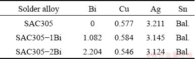
Three solder alloy formulations were melted for experimental use: Sn-3.0Ag-0.5Cu (SAC305), Sn-3.0Ag-0.5Cu-1Bi (SAC305-1Bi), and Sn- 3.0Ag-0.5Cu-2Bi (SAC305-2Bi). The solder alloys were prepared using high purity Sn, Ag, Cu, and Bi ingots. Ingots were put into a graphite crucible and melted in an electric arc furnace at 400 °C for 4 h under ambient pressure. Before casting, the temperature of the melt was reduced to 250 °C to prevent oxide film forming and the steel mold was preheated to 200 °C. After that, the molten solder alloy was poured and when the alloy was cooled to 100 °C, it was released and removed from the mold. The chemical compositions of the three solder alloys were analyzed by X-ray fluorescence spectrometry (XRF, PW2400, Philips) (Table 1).
Table 1 Chemical compositions of SAC305-xBi solder alloys (wt.%)
For tensile testing, as-cast solder alloy samples were machined following the ASTM E8 standard (diameter of 6 mm and gauge length of 30 mm). To prepare the solder pad used in the soldering process, as-cast solder alloy samples were cold-rolled by a two-roll mill (XK-160, Xincheng) to a thickness of 0.2 mm. After rolling, the solder pad was cut to dimensions of 10 mm × 10 mm × 0.2 mm, washed with distilled water in an ultrasonic cleaner for 30 min and dried in an oven at 80 °C for 30 min. To prepare the copper substrate, copper pads were cut to dimensions of 10 mm × 50 mm × 3 mm, abraded with SiC-papers (P240 and P600), immersed in a dilute HCl solution for 30 min, washed with ethanol (C2H5OH) and dried by hot air blower.
2.2 Soldering process
A single lap joint method was used in the soldering process. Two copper pads were painted with rosin mildly activated (RMA) flux on a single overlapping joint. RMA flux prevented the formation of oxide film and enhanced the wetting property of the solder in the molten state. The two copper pads were put on the reflow block, and the solder pad was inserted into the gap between the two copper pads (gap ~0.2 mm) and fixed under the clamp of the reflow block. A type K thermocouple was connected to the sample and the reflow block to measure temperatures during the soldering process. The assembled reflow block was put on the heating plate, raised up to 250 °C, held for 2 min under ambient atmosphere, then moved from the heating plate and released to cool down to room temperature. Soldered joints received after the soldering process were called as-reflowed solder joints. The soldering setup is shown in Fig. 1.
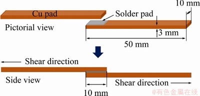
Fig. 1 Schematic of single lap solder joint for shear testing
2.3 Materials characterization
Samples for microstructural observation were cut into small pieces which were cold-mounted with epoxy resin. After that, the sample was abraded with SiC-papers (P240, P400, P600, P1200, and P2500), polished with 5, 1 and 0.05 mm Al2O3 suspensions, and etched for 5 s with an acid solution of 55% HCl + 15% H2O + 15% HNO3 + 15%CH3COOH (volume fraction). The micro- structural observation and phase identification were examined by an optical microscope (OM, Olympus, BX 53), a scanning electron microscope (SEM, Quanta 400, FEI) coupled to an energy dispersive X-ray spectroscope (EDS, Oxford, X-MaxN20), and an X-ray diffractometer (XRD, X'Pert MPD, Philips). The thermal properties of alloys were measured in two steps to obtain heating and cooling curves by differential scanning calorimeter (DSC, NETZSCH, DSC 200 F3 Maia). The sample was heated and cooled from 30 to 300 °C in a nitrogen atmosphere at heating and cooling rates of 10 °C/min. Tensile and shear tests were performed using a universal testing machine (UTM, Instron 5569) at room temperature and constant strain rates of 1.5 mm/min for tensile testing and 1.0 mm/min for shear testing. The tensile and shear strength values were obtained by averaging five test results. The average microhardness of solder alloys was determined by the Vickers microhardness test (INNOVATEST, NOVA 130/240) at a load of 200 g and dwell time of 10 s. The thickness of the interfacial layer between the solder and Cu substrate was analyzed by image tool software and the thickness of IMC layers was calculated as follows [5]:
h=A/L (1)
where h is the thickness of the IMC layer, A is the area of the IMC layer obtained from the SEM micrograph using the image tool program, and L is the length of the IMC layer along the interface.
3 Results and discussion
3.1 Microstructure of as-cast solder alloys
The microstructure of the SAC305 solder alloys was composed of β-Sn and eutectic phases. The eutectic phase consisted of Ag3Sn and Cu6Sn5 IMCs dispersed within a β-Sn matrix (Fig. 2(a)) [10-12,18]. The β-Sn and eutectic phases were refined by the addition of 1 and 2 wt.% Bi (Figs. 2(b, c), respectively) because Bi reduced the undercooling (△T) of solder alloys and increased the heterogeneous nucleation sites, caused faster solidification rate of IMCs and β-Sn phases, as a result, SAC305 containing Bi was the refined microstructure [28,29]. The eutectic phase of the SAC305-2Bi solder alloy was composed of Ag3Sn and Cu6Sn5 IMCs, and Bi particles dispersed within the β-Sn matrix. The IMC phases of SAC305 and SAC305-2Bi were confirmed by XRD analysis (Fig. 3). SEM-EDS analysis of the eutectic region of the SAC305 solder alloy revealed fiber-like Ag3Sn and plate-like Cu6Sn5 particle distributions within the β-Sn matrix (Figs. 4(a-d)). The eutectic region of the SAC305-2Bi solder alloy consisted of Ag3Sn, Cu6Sn5 IMC and Bi particles dispersed within the β-Sn matrix (Figs. 4(e-h)). The addition of Bi equal to or greater than 2 wt.% formed precipitates of Bi in the β-Sn matrix because at room temperature the solubility limit of Bi in Sn was about 1.0 wt.% [25,26]. Bi particles were uniformly dispersed in a nearly IMC phase (Fig. 4(e)). The elemental mapping image of the solder alloys shows the distribution of all elements in the β-Sn matrix. Ag and Cu elements were present in the eutectic region (Figs. 5(a-e)). Elemental Bi was distributed in a nearly IMC phase in the eutectic region (Figs. 5(f-k)). In SAC305 solder alloy containing 2 wt.% Bi, precipitated Bi particles were present within the eutectic region and precipitation strengthening occurred. These results corresponded with previous reports of solder alloys containing Bi [25,26,28-30].
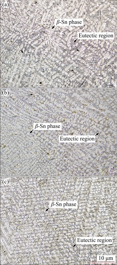
Fig. 2 OM images of SAC305 (a), SAC305-1Bi (b), and SAC305-2Bi (c) solder alloys
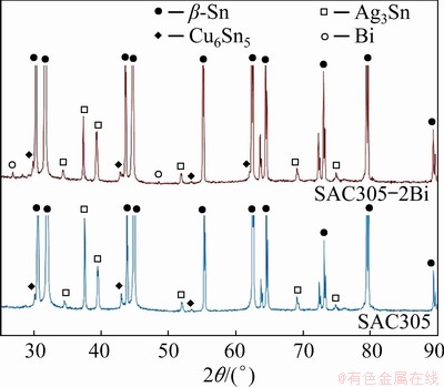
Fig. 3 XRD patterns of SAC305 and SAC305-2Bi solder alloys
3.2 Mechanical performance of as-cast solder alloys
The stress-strain curves of the SAC305, SAC305-1Bi, and SAC305-2Bi solder alloys showed deformation behavior in three states: elastic deformation, plastic deformation, and fracture point. The addition of 1 and 2 wt.% Bi increased the stress of the solder alloys (Fig. 6(a)). The Bi addition also increased the mechanical performance in terms of ultimate tensile strength (UTS) and microhardness while elongation (EL) decreased (Figs. 6(b) and Fig. 7). The UTS of the alloys increased from 35.7 MPa for SAC305 solder alloy to 48.6 MPa and 55.3 MPa for SAC305-1Bi and SAC305-2Bi, respectively, while microhardness increased from 12.6 HV to 18.6 HV and 20.8 HV. EL decreased from 24.6% for SAC305 to 19.3% and 16.1% for SAC305-1Bi and SAC305-2Bi, respectively. The changes in the mechanical performance were mainly attributed to the combined effects of grain boundary strengthening, solid solution strengthening and the precipitation strengthening mechanism [24,25,31].
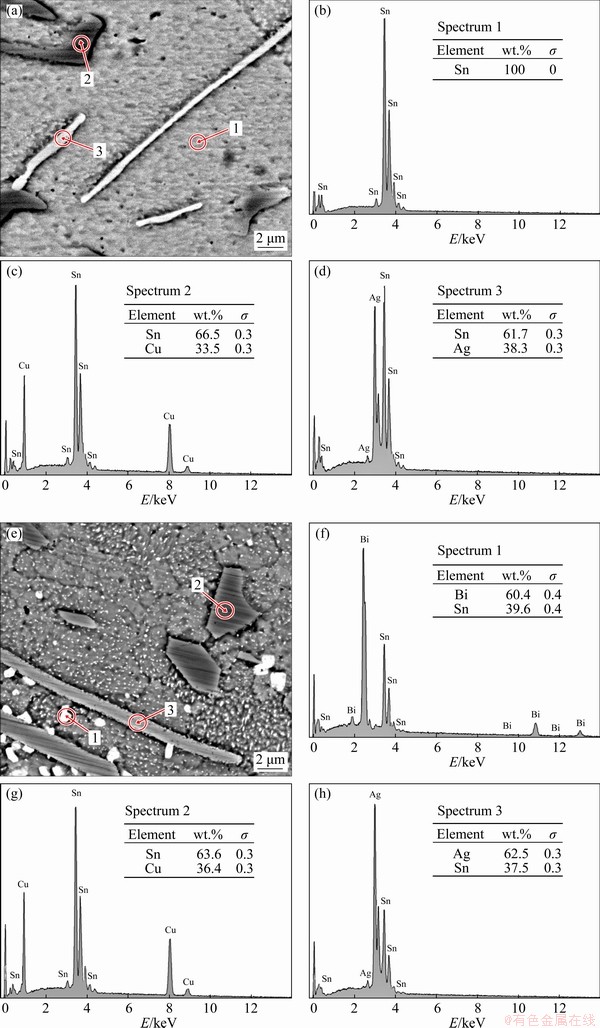
Fig. 4 SEM-EDS point scan images of SAC305 (a-d) and SAC305-2Bi (e-h) solder alloys

Fig. 5 SEM-EDS mapping images of SAC305 (a-e) and SAC305-2Bi (f-k) solder alloys
The microstructural study of the alloys revealed refinement of the β-Sn and eutectic phases due to the addition of Bi to the SAC305 solder alloy (Fig. 2). Grain refining is one of the strengthening mechanisms that increase UTS and microhardness. This phenomenon can be explained by the Hall-Petch relationship by which the strength of a polycrystalline material increases as its grain size decreases [14]. Moreover, a small amount of Bi could dissolve in the β-Sn matrix to form a solid solution. But if the addition of Bi is equal to or greater than 2 wt.%, precipitates of Bi will form in the β-Sn matrix. Solid solution, Bi precipitation, and homogeneous dispersion of the IMC phase in the β-Sn matrix inhibited dislocation movement and enhanced the mechanical performance of solder alloys [26,27,32]. This result is similar to the study results of SAYYADI and NAFFAKH-MOOSAVY [28,29]. The small amount addition of Bi (≤2.5 wt.%) to SAC solder alloys formed a solid solution and refined precipitate of Bi in the solder matrix that prevented the movement of the dislocations, as a result, increased the strength of solders. In contrast, the high amount addition of Bi (5 wt.%) formed a large number of Bi precipitates in solder matrix. These precipitates are brittle, which deteriorate the mechanical performance of solders [28,29]. After tensile testing at room temperature, the fracture surface of the SAC305 solder alloy sample showed necking in the cross- sectional area (Fig. 8(a)) and exhibited dimple structures that were identified as a ductile fracture mode (Fig. 8(b)). At lower magnification, a cross-sectional area of the SAC305-2Bi solder alloy showed a brittle fracture with very little plastic deformation and no necking, whereas at higher magnification, cleavage planes were observed with a few dimple structures. These chatacteristics also indicated a brittle fracture mode (Figs. 8(c, d)). The results of fracture surface analysis were consistent with the stress-strain curves presented in Fig. 6(a) and with the increased UTS and reduced EL of the SAC305-xBi solder alloys (Fig. 6(b)). This result is similar to that obtained by SAYYADI and NAFFAKH- MOOSAVY [28].

Fig. 6 Stress-strain curves (a), UTS and EL (b) of tensile testing samples

Fig. 7 Microhardness of solder alloys
3.3 Thermal behavior of as-cast solder alloys
Thermal behavior influences reflow soldering, wetting and solidification after soldering. The thermal profiles of the solder alloys during heating and cooling processes were analyzed by DSC. The heating curves of the SAC305, SAC305-1Bi, and SAC305-2Bi solder alloys exhibited only one endothermic peak (Fig. 9(a)). The results of DSC analysis were presented in Table 2. The peak temperature (Tm) of SAC305 occurred at 221.6 °C, and the solidus temperature (Tonset) was 217.2 °C. The addition of Bi reduced both Tm and Tonset of the SAC305 solder alloy due to the reaction between Sn and Bi, creating a new Sn―Bi bond. As a result, the atomic displacement in the crystal structure occurred much more easily and the melting temperature of solders decreased [28,29]. Tm and Tonset decreased from 221.6 and 217.2 °C for SAC305 to 217.3 and 214.5 °C for SAC305-2Bi, respectively. The pasty range of the solder alloys was calculated from Tend-Tonset (Tend is the liquidus temperature) during the heating process. The pasty ranges of SAC305, SAC305-1Bi, and SAC305-2Bi solder alloys were 6.9, 9.0, and 5.7 °C, respectively (Table 2), which were smaller than the pasty range of Sn-37Pb solder alloy (11.5 °C) [33]. Undercooling was determined from Tonset (heating)-Tonset (cooling). The undercooling ranges of the solder alloys were 28.0, 24.5, and 27.7 °C for SAC305, SAC305-1Bi, and SAC305-2Bi, respecticvely (Table 3). According to previous research, the nucleation and solidification of SAC solder alloys had undercooling values within 15-30 °C [34,35]. The addition of Bi to the SAC305 solder alloy slightly decreased the degree of undercooling. The reduction of undercooling is known to encourage nucleation behaviors and increase the nucleus during solidification of liquid solders, which consequently results in more refined structures. The results of thermal analysis in this study were in agreement with previous reports of solder alloys containing Bi [24,25,28-30].

Fig. 8 Fracture surfaces of SAC305 (a, b), and SAC305-2Bi (c, d) solder alloys
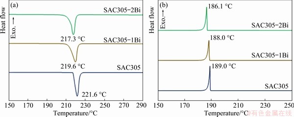
Fig. 9 DSC curves of solder alloys during heating (a) and cooling (b) processes
Table 2 General characterization of peak temperature (Tm), solidus temperature (Tonset), liquidus temperature (Tend), and pasty range (Tend-Tonset) of solder alloys from heating curves
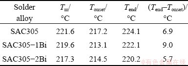
Table 3 Undercooling △T (=Tonset,heating-Tonset,cooling) of solder alloys determined from solidus temperature during heating (Tonset,heating) minus liquidus temperature during cooling (Tonset,cooling)

3.4 Morphology of interfacial layer of solder joints
The interfacial layers formed between joints of all the solder alloys and the Cu substrate were examined after soldering at 250 °C for 2 min. All the interfacial layers were composed of two IMC layers. Firstly, a layer of scallop-shaped Cu6Sn5 IMCs formed at the interface during the soldering process and then a second layer of Cu3Sn IMCs formed between the Cu6Sn5 IMC layer and the Cu substrate (Figs. 10(a-c)) [13,36-38]. In the Sn-Cu phase diagram system, Cu6Sn5 and Cu3Sn phases can form during soldering at temperatures below 350 °C due to the interfacial reaction between Sn atoms from the bulk solder and Cu atoms from the substrate. The reactions were described by Eqs. (2) and (3) [24,39,40].
6Cu+5Sn Cu6Sn5 (2)
3Cu+SnCu3Sn (3)
The chemical composition of IMC layers was identified by EDS analysis. The Cu6Sn5 IMC layer of SAC305/Cu solder joint was composed of 62.0 wt.%Sn-38.0wt.%Cu and the Cu3Sn layer was 74.3wt.%Cu-25.7wt.%Sn (Figs. 11(a-d)). The Cu6Sn5 IMC layer of the SAC305-2Bi/Cu solder joint was composed of 62.7wt.%Sn-37.3wt.%Cu and the Cu3Sn IMC layer was 72.2wt.%Cu- 27.8wt.%Sn (Figs. 11(e-h)). Also, particulate phases of Ag3Sn and SnBi IMCs were present in the bulk solders above the interfacial layer of solder joints. Measurements of the thickness of the interfacial layers of SAC305/Cu, SAC305-1Bi/Cu, and SAC305-2Bi/Cu revealed the influence of Bi (Table 4). The thickness of the IMC layers decreased with increasing Bi content. The combined thickness of the Cu6Sn5 IMC and the Cu3Sn IMC layers decreased from 12.03 mm in the SAC305/Cu solder joint to 7.36 mm in the SAC305-2Bi/Cu solder joint. The Bi addition reduced the solubility of Cu and slowed down the reaction rate between the molten solder and the Cu substrate. As a result, the total thickness of the interfacial IMC layer decreased. In addition, Bi did not dissolve during the reaction and growth of the Cu6Sn5 IMC layer. The resultant concentration of Bi slowed the growth of the IMC layers [38]. This result is consistent with previous reports of Sn-Cu-Ni-xBi (x=0, 0.5, 1.5, 2, 5, 8, 10, 14) [4,6], Sn-Ag-xBi (x=0, 1, 2, 3, 4) [38], and Sn-Ag-Cu- xBi (x=0, 1, 2.5, 5) [29,39].

Fig. 10 Morphologies of interfacial layers of SAC305/Cu (a), SAC305-1Bi/Cu (b), and SAC305-2Bi/Cu (c) solder joints
3.5 Shear test results of solder joints
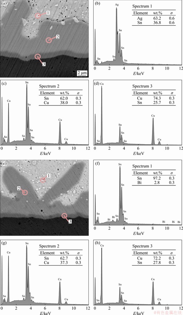
Fig. 11 SEM images and EDS results of interfacial IMC layers of SAC305/Cu (a-d), and SAC305-2Bi/Cu (e-h) solder joints
Figure 12 show the shear test results and their average shear strength values of different solder joints. The average shear strength of solder joints increased from 20.48 MPa for SAC305/Cu to 31.06 MPa for SAC305-2Bi/Cu (Fig. 12(d)). The increase in shear strength correlated with the strength values previously obtained and thickness of the IMCs presented in Table 4. The thickness of interfacial IMC layers controlled mechanical properties of solder joints, and the shear strength of solder joints increased. An addition of Bi less than 2 wt.% could dissolve in the β-Sn matrix and form a solid solution strengthening mechanism. Additions equal to or greater than 2 wt.% Bi resulted in Bi precipitation in the β-Sn matrix and the formation of a precipitation strengthening mechanism. Both of these mechanisms improved the strength of solder joints [6,32,41]. According to SAYYADI and NAFFAKH-MOOSAVY [29], the high amount addition of Bi (5 wt.%) to SAC solder joints formed a large number of Bi precipitates in the matrix. These precipitates were brittle, which caused the reduction of the shear strength and ductility of solder joints. From shear testing at room temperature, the fracture surface of SAC305/Cu solder joints at low and high magnifications exhibited more dimples along the shear direction, which indicated a ductile fracture process with plastic deformation (Figs. 13(a, b)). The shear fracture pattern of the SAC305-2Bi/Cu solder joint was a mixture of ductile and brittle failure because the fracture surfaces consisted of small dimples and a cleavage surface (Figs. 13(c, d)). Therefore, it was assumed that ductile fracture occurred in the bulk solder region, while mixed fracture occurred near solder/ interface layer region. The fracture mode depended on the thickness of the interfacial IMC layer and the strength of the solder joint [29,42].
Table 4 Thickness of interfacial IMC layer after reflowing at 250 °C and holding for 2 min
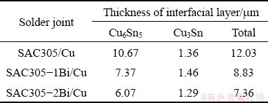
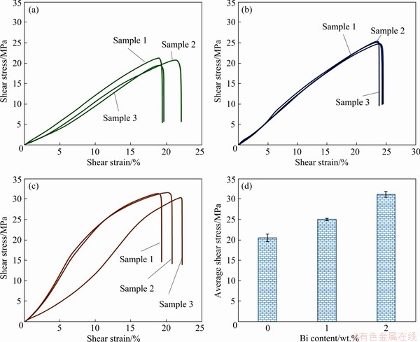
Fig. 12 Shear test results of SAC305/Cu (a), SAC305-1Bi/Cu (b), SAC305-2Bi/Cu (c) solder joints, and their average shear strength values (d)

Fig. 13 Shear fracture surface morphologies for SAC305/Cu (a, b), and SAC305-2Bi/Cu (c, d) solder joints
4 Conclusions
(1) The addition of elemental Bi improved the microstructure of the SAC305 solder alloy by refining the primary β-Sn and eutectic phases (Ag3Sn and Cu6Sn5). Adding less than 2 wt.% Bi created a solid solution. Adding 2 wt.% Bi or more created Bi precipitates in the β-Sn matrix.
(2) The addition of the Bi improved the thermal properties of the SAC305 solder alloy by reducing the melting point and slightly reducing the degree of undercooling.
(3) The addition of Bi improved the mechanical performance of the SAC305 solder alloy by increasing UTS, microhardness and shear strength due to the effects of solid solution strengthening and precipitation strengthening mechanisms.
(4) The interfacial layer of all solder joints was composed of two parallel IMC layers of Cu6Sn5 and Cu3Sn, which were formed during the soldering process. Also, the addition of Bi reduced the thickness of the interfacial layer.
(5) 2 wt.% Bi was the optimal condition which best improved the microstructure and mechanical performance of the SAC305 solder alloy.
Acknowledgments
The provision of lab facilities and financial support by the Division of Physical Science, Faculty of Science, Prince of Songkla University (PSU) is gratefully acknowledged. We would like to thank academician Thomas Duncan Coyne for commenting and improving the English in the manuscript.
References
[1] DOI K, OHTANI H, HASEBE M. Thermodynamic study of the phase equilibria in the Sn-Ag-Bi-Cu quaternary system [J]. Materials Transactions, 2004, 45: 380-383.
[2] EL-DALY A A, HAMMAD A E. Development of high strength Sn-0.7Cu solders with the addition of small amount of Ag and In [J]. Journal of Alloys and Compounds, 2011, 509: 8854-8860.
[3] MUSTAFA ERER A, OGUZ S, TUREN Y. Influence of bismuth (Bi) addition on wetting characteristics of Sn-3Ag-0.5Cu solder alloy on Cu substrate [J]. Engineering Science and Technology, 2018, 21: 1159-1163.
[4] BELYAKOV S A, XIAN J W, SWEATMAN K, NISHIMURA T, AKAIWA T, GOURLAY C M. Influence of bismuth on the solidification of Sn-0.7Cu-0.05Ni-xBi/Cu joints [J]. Journal of Alloys and Compounds, 2017, 701: 321-334.
[5] LU Tao, YI Dan-qing, WANG Hong-xuan, TU Xiao-xuan, WANG Bin. Microstructure, mechanical properties, and interfacial reaction with Cu substrate of Zr-modified SAC305 solder alloy [J]. Journal of Alloys and Compounds, 2019, 781: 633-643.
[6] RAMLI M I I, MOHD SALLEH M A A, YASUDA H, CHAIPRAPA J, NOGITA K. The effect of Bi on the microstructure, electrical, wettability and mechanical properties of Sn-0.7Cu-0.05Ni alloys for high strength soldering [J]. Materials & Design, 2020, 186: 108281.
[7] KOTADIA H R, HOWES P D, MANNAN S H. A review: On the development of low melting temperature Pb- free solders [J]. Microelectronics Reliability, 2014, 54: 1253-1273.
[8] REN G, WILDING I J, COLLINS M N. Alloying influences on low melt temperature SnZn and SnBi solder alloys for electronic interconnections [J]. Journal of Alloys and Compounds, 2016, 665: 251-260.
[9] SUGANUMA K. Advances in lead-free electronics soldering [J]. Current Opinion in Solid State and Materials Science, 2011, 5: 55-64.
[10] EL-DALY A A, FAWZY A, MANSOUR S F, YOUNIS M J. Novel SiC nanoparticles containing Sn-1.0Ag-0.5Cu solder with good drop impact performance [J]. Materials Science and Engineering A, 2013, 578: 62-71.
[11] EL-DALY A A, AL-GANAINY G S, FAWZY A, YOUNIS M J. Structural characterization and creep resistance of nano-silicon carbide reinforced Sn-1.0Ag-0.5Cu lead-free solder alloy [J]. Materials & Design, 2014, 55: 837-845.
[12] EL-DALY A A, EL-TAHER A M, DALLOUL T R. Enhanced ductility and mechanical strength of Ni-doped Sn-3.0Ag-0.5Cu lead-free solders [J]. Materials & Design, 2014, 55: 309-318.
[13] HONGYAN Xu, ZHANGFU Yuan. Interfacial reaction kinetics between liquid Sn-Ag-Cu alloys and Cu substrate [J]. Rare Metal Materials and Engineering, 2014, 43: 2893-2897.
[14] IZWAN I, SAUD N, MOHD SALLEH M A A, DERMAN M N, SAID R M, NASIR N M. Microstructural observation and phase analysis of Sn-Cu-Ni (SN100C) lead free solder with addition of micron-size silicon nitride (Si3N4) reinforcement [J]. Applied Mechanics and Materials, 2015, 754-755: 518-523.
[15] HAMMAD A E. Enhancing the ductility and mechanical behavior of Sn-1.0Ag-0.5Cu lead-free solder by adding trace amount of elements Ni and Sb [J]. Microelectronics Reliability, 2018, 87: 133-141.
[16] EL-BASATY A B, DEGHADY A M, EID E A. Influence of small addition of antimony (Sb) on thermal behavior, microstructural and tensile properties of Sn-0.9Zn-0.5Al Pb-free solder alloy [J]. Materials Science and Engineering A, 2017, 701: 245-253.
[17] WANG Yao-li, WANG Guang-xin, SONG Ke-xing, ZHANG Ke-ke. Effect of Ni addition on the wettability and microstructure of Sn2.5Ag0.7Cu0.1RE solder alloy [J]. Materials & Design, 2017, 119: 219-224.
[18] EL-DALY A A, HAMMAD A E, AL-GANAMY G S, RAGAB M. Properties enhancement of low-Ag content Sn-Ag-Cu lead-free solders containing small amount of Zn [J]. Journal of Alloys and Compounds, 2014, 641: 20-28.
[19] LUO Zhong-bing, ZHAO Jian-fei, GAO Yan-jun, WANG Lai. Revisiting mechanisms to inhibit Ag3Sn plates in Sn-Ag-Cu solders with 1 wt.% Zn addition [J]. Journal of Alloys and Compounds, 2010, 500: 39-45.
[20] SHALABY R M. Influence of indium addition on structure, mechanical, thermal and electrical properties of tin- antimony based metallic alloys quenched from melt [J]. Journal of Alloys and Compounds, 2009, 480: 334-339.
[21] CHUANG C L, TSAO L C, LIN H K , FENG L P. Effects of small amount of active Ti element additions on microstructure and property of Sn3.5Ag0.5Cu solder [J]. Materials Science and Engineering A, 2012, 558: 478-484.
[22] TU Xiao-xuan, YI Dan-qing, WU Jing, WANG Bin. Influence of Ce addition on Sn-3.0Ag-0.5Cu solder joints: Thermal behavior, microstructure and mechanical properties [J]. Journal of Alloys and Compounds, 2017, 698: 317-328.
[23] GAO Li-li, XUE Song-bai, ZHANG Liang, SHENG Zhong, ZENG Guang, JI Feng. Effects of trace rare earth Nd addition on microstructure and properties of SnAgCu solder [J]. Journal of Materials Science: Materials in Electronics, 2010, 21(7): 643-648.
[24] HU Xiao-wu, LI Yu-long, LIU Yi, MIN Zhi-xian. Developments of high strength Bi-containing Sn0.7Cu lead-free solder alloys prepared by directional solidification [J]. Journal of Alloys and Compounds, 2015, 625: 241-250.
[25] EL-DALY A A, EL-TAHER A M, GOUDA S. Novel Bi-containing Sn-1.5Ag-0.7Cu lead-free solder alloy with further enhanced thermal property and strength for mobile products [J]. Materials & Design, 2015, 65: 796-805.
[26] ZHAO Jie, QI Lin, WANG Xiu-min, WANG Lai. Influence of Bi on microstructure evolution and mechanical properties in Sn-Ag-Cu lead-free solder [J]. Journal of Alloys and Compounds, 2004, 375: 196-201.
[27] LIU Yang, SUN Feng-lian, LI Xue-mei. Effect of Ni, Bi concentration on the microstructure and shear behavior of low-Ag SAC-Bi-Ni/Cu solder joints [J]. Journal of Materials Science: Materials in Electronics, 2014, 25: 2627-2633.
[28] SAYYADI R, NAFFAKH-MOOSAVY H. Physical and mechanical properties of synthesized low Ag/lead-free Sn-Ag-Cu-xBi (x=0, 1, 2.5, 5 wt.%) solders [J]. Materials Science and Engineering A, 2018, 735: 367-377.
[29] SAYYADI R, NAFFAKH-MOOSAVY H. The role of intermetallic compounds in controlling the microstructural, physical and mechanical properties of Cu-[Sn-Ag-Cu-Bi]- Cu solder joints [J]. Scientific Reports, 2019, 9: 1-20.
[30] MAHDAVIFARD M H, SABRI M F M, SHNAWAH D A, SAID S M, BADRUDDIN I A, ROZALI S. The effect of iron and bismuth addition on the microstructural, mechanical, and thermal properties of Sn-1Ag-0.5Cu solder alloy [J]. Microelectronics Reliability, 2015, 55: 1886-1890.
[31] ALI B, SABRI M F M, SAID S M, SUKIMAN N L, JAUHARI I, MAHDAVIFARD M H. Microstructure and tensile properties of Fe and Bi added Sn-1Ag-0.5Cu solder alloy under high temperature environment [J]. Microelectronics Reliability, 2018, 82: 171-178.
[32] SHEN Jun, PU Ya-yun, WU Dong, TANG Qin, ZHAO Ma-li. Effects of minor Bi, Ni on the wetting properties, microstructures, and shear properties of Sn-0.7Cu lead-free solder joints [J]. Journal of Materials Science: Materials in Electronics, 2015, 26: 1572-1580.
[33] WANG Jian-xin, YIN Ming, LAI Zhong-min, LI Xue. Wettability and microstructure of Sn-Ag-Cu-In solder [J]. Transactions of the China Welding Institution, 2011, 32: 69-73.
[34] ANDERSON I E. Development of Sn-Ag-Cu and Sn-Ag-Cu-X alloys for Pb-free electronic solder applications [J]. Journal of Materials Science: Materials in Electronics, 2007, 18: 55-76.
[35] KANG S K, SHIH D Y, DONALD N Y, HENDERSON W, GOSSELIN T, SARKHEL A, CHARLES GOLDSMITH N Y, PUTTLITZ K J, CHOI W K. Ag3Sn plate formation in the solidification of near-ternary eutectic Sn-Ag-Cu [J]. Journal of the Minerals, Metals & Materials Society, 2003, 55: 61-65.
[36] LIANG J, DARIAVACH N, CALLAHAN P, SHANGGUAN D. Metallurgy and kinetics of liquid-solid interfacial reaction during lead-free soldering [J]. Materials Transections, 2006, 47: 317-325.
[37] MOHD SALLEH M A A, MCDONALD S D, GOURLAY C M , BELYAKOV S A, YASUDA H, NOGITA K. Effect of Ni on the formation and growth of primary Cu6Sn5 intermetallics in Sn-0.7wt.%Cu solder pastes on Cu substrates during the soldering process [J]. Journal of Electronic Materials, 2016, 45: 154-163.
[38] HE M, ACOFF V L. Effect of Bi on the interfacial reaction between Sn-3.7Ag-xBi solders and Cu [J]. Journal of Electronic Materials, 2008, 37: 288-299.
[39] HODULOVA E, PALCUT M, LECHOVIC E, SIMEKOVA B, ULRICH K. Kinetics of intermetallic phase formation at the interface of Sn-Ag-Cu-X (X=Bi, In) solders with Cu substrate [J]. Journal of Alloys and Compounds, 2011, 509: 7052-7059.
[40] LAURILA T, VUORINEN V, KIVILAHTI J K. Interfacial reactions between lead-free solders and common base materials [J]. Materials Science and Engineering R, 2005, 49: 1-60.
[41] TATEYAMA K, UBUKATA H, YAMAOKA Y, TAKAHASHI K, YAMADA H, SAITO M. Effects of Bi content on mechanical properties and bump interconnection reliability on Sn-Ag solder alloys [J]. International Journal of Microcircuits and Electronic Packaging, 2000, 23: 131-137.
[42] ZHAO Jie, CHENG Cong-qian, QI Lin, CHI Cheng-yu. Kinetics of intermetallic compound layers and shear strength in Bi-bearing SnAgCu/Cu soldering couples [J]. Journal of Alloys and Compounds, 2009, 473: 382-388.
Suchart CHANTARAMANEE1, Phairote SUNGKHAPHAITOON2,3
1. Department of Industrial Engineering, Faculty of Engineering, Rajamangala University of Technology Srivijaya, 90000 Songkhla, Thailand;
2. Division of Physical Science, Faculty of Science, Prince of Songkla University, 90112 Hat Yai, Thailand;
3. Center of Excellence in Metal and Materials Engineering, Faculty of Engineering, Prince of Songkla University, 90112 Hat Yai, Thailand
摘 要:通过添加1% 和2%(质量分数)的Bi提高SAC305焊接接头的性能,并研究Bi掺杂对SAC305-xBi/Cu焊接接头显微组织、热性能和力学性能的影响。Bi掺杂通过细化初始β-Sn和共晶相改善焊接接头的显微组织。当Bi含量低于2% 时,Bi溶解到β-Sn基体中形成固溶体;而当Bi含量等于或高于2%时,β-Sn基体中形成Bi的沉淀相。β-Sn基体中的固溶强化和析出强化机制使合金的极限抗拉强度和硬度分别从35.7 MPa 和12.6 HV 提高到55.3 MPa和20.8 HV,但是伸长率从24.6%降至16.1%。含2% Bi焊接接头断口呈典型脆性断裂形貌。所有焊接接头的界面层由两个平行的IMC层组成:Cu6Sn5层和Cu3Sn层。与SAC305/Cu焊接接头相比,SAC305-xBi/Cu焊接接头的界面层更薄,剪切强度更高。因此,添加少量Bi可以细化SAC305/Cu焊接接头的显微组织,降低熔点并提高其力学性能。
关键词:Sn-3.0Ag-0.5Cu焊料合金;界面行为;力学性能;强化效果;热性能
(Edited by Wei-ping CHEN)
Corresponding author: Phairote SUNGKHAPHAITOON, E-mail: phairote.s@psu.ac.th, p.sungkhaphaitoon@gmail.com
DOI: 10.1016/S1003-6326(21)65585-1
1003-6326/ 2021 The Nonferrous Metals Society of China. Published by Elsevier Ltd & Science Press

