����ѡ���ۻ�AlSi10Mg�Ͻ�ĸ���ƣ�����ܺͶ�����Ϊ
��Դ�ڿ����й���ɫ����ѧ��(Ӣ�İ�)2020���10��
�������ߣ�S. GLODEZ J. KLEMENC F. ZUPANIC M. VESENJAK
����ҳ�룺2577 - 2589
�ؼ��ʣ�����ѡ���ۻ���AlSi10Mg�Ͻ𣻸���ƣ�ͣ�������Ϊ
Key words��selective laser melting; AlSi10Mg alloy; high-cycle fatigue; fracture behaviour
ժ Ҫ���о�����ѡ���ۻ�(SLM) AlSi10Mg�Ͻ��ƣ�����ܺͶ�����Ϊ�������������غ�(R=0��RΪ��̬����)�£�����״����ֱ����Ƴ�ƣ������������״������Weibull���������ܶȺ�����ƣ��-����(S-N)���߽��н�ģ������ʵֵ�Ŵ��㷨(GA)�Ͳ����Ⱥ�㷨(DASA)���������Weibull������ƣ�������ĶϿ���ò������ƣ��������SLM��Ʒ�ı���ȱ����Χ���������Բ��ȶ��ķ�ʽ��չ��Ȼ���� SLM��ȱ�ݵĴ�����ҪӰ�������������ڣ���������չӰ�첻������ʵ������Ϊ��һ���о����������Ƚ����Ϻͽṹ(���Ԫ������)��ƣ����Ϊ�ṩ�������ر����ڶ�ά��Ԫ�ṹ�У���Ԫ�ṹ��Ľ���ͨ��Ϊ���Σ��뱾�о��е�������״���Ӧ��
Abstract: The high-cycle fatigue and fracture behaviours of the selective laser melting (SLM) AlSi10Mg alloy were investigated. Flat specimens were designed directly in the shape required for the fatigue tests under pulsating loading in tension (R=0, R is the dynamic factor). The fatigue-life (S-N) curves were modelled with a conditional Weibull��s probability density function, where the real-valued genetic algorithm (GA) and the differential ant-stigmergy algorithm (DASA) were applied to estimating the needed Weibull��s parameters. The fractography of the fatigue specimens showed that the fatigue cracks initiated around the surface defects produced by SLM and then propagated in an unstable manner. However, the presence of large SLM defects mainly influenced the crack initiation period and did not have a strong influence on the crack propagation. The obtained experimental results present a basis for further investigation of the fatigue behaviour of advanced materials and structures (e.g. cellular metamaterials) fabricated by additive manufacturing (AM). Especially, in the case of two-dimensional cellular structures, the cross-section of cellular struts is usually rectangular which corresponds to the specimen shape considered in this work.
Trans. Nonferrous Met. Soc. China 30(2020) 2577-2589
S. GLODEZ1, J. KLEMENC2, F. ZUPANIC1, M. VESENJAK1
1. Faculty of Mechanical Engineering, University of Maribor, Smetanova 17, 2000 Maribor, Slovenia;
2. Faculty of Mechanical Engineering, University of Ljubljana, ASkerCeva 6, 1000 Ljubljana, Slovenia
Received 31 January 2020; accepted 20 August 2020
Abstract: The high-cycle fatigue and fracture behaviours of the selective laser melting (SLM) AlSi10Mg alloy were investigated. Flat specimens were designed directly in the shape required for the fatigue tests under pulsating loading in tension (R=0, R is the dynamic factor). The fatigue-life (S-N) curves were modelled with a conditional Weibull��s probability density function, where the real-valued genetic algorithm (GA) and the differential ant-stigmergy algorithm (DASA) were applied to estimating the needed Weibull��s parameters. The fractography of the fatigue specimens showed that the fatigue cracks initiated around the surface defects produced by SLM and then propagated in an unstable manner. However, the presence of large SLM defects mainly influenced the crack initiation period and did not have a strong influence on the crack propagation. The obtained experimental results present a basis for further investigation of the fatigue behaviour of advanced materials and structures (e.g. cellular metamaterials) fabricated by additive manufacturing (AM). Especially, in the case of two-dimensional cellular structures, the cross-section of cellular struts is usually rectangular which corresponds to the specimen shape considered in this work.
Key words: selective laser melting; AlSi10Mg alloy; high-cycle fatigue; fracture behaviour
1 Introduction
Additive manufacturing (AM) is a fabrication process, which provides unique opportunities to manufacture customized parts with complex geometries or functionally graded materials [1,2]. Many AM technologies are being currently used in different engineering applications especially in automotive and aerospace industry [3,4]: direct metal laser sintering (DMLS), selective laser melting (SLM), electron beam melting (EBM), laser metal deposition (LMD), etc. Among the AM processes, DMLS and SLM techniques are particularly widespread, especially for aluminium alloy processing [5,6]. The DMLS technology is appropriate to build parts out of any metal alloy, while SLM can only be used with certain metals.
With the advancements in AM technology over the last years, dense machine parts with mechanical properties comparable to the conventional manufacturing methods can be achieved for different engineering materials [7]. In general, the static strength of AM parts depends on their density, as well as on the microstructure formed during AM process. As presented by ABOULKHAIR et al [8] and KEMPEN et al [9], the microstructure of AM-fabricated parts is usually finer (higher static strength) compared with that of the parts, which are fabricated via classical procedures (e.g. casting). On the other hand, the microstructure of AM-fabricated parts is anisotropic and corresponds to the building direction during AM process. Consequently, the tensile properties (proportional limit, ultimate tensile strength) are also anisotropic and may strongly depend on the orientation of texture [10-13]. ZHOU et al [14] have shown that the microstructure, hardness and static strength of AM parts may be significantly influenced by the additional heat treatment after AM process.
Nevertheless, the fatigue behaviour of AM parts has not been yet well understood, thus delaying the widespread adoption of this advanced manufacturing technology in a variety of engineering applications. Identical to static mechanical properties, the fatigue strength of AM parts primarily depends on their microstructure. Here, it should be taken into account that the manufacturing process using AM technology usually leads to an increased surface roughness, causing increased stress concentration and early failure of AM parts under fatigue loading in the fabricated condition [15,16]. Mechanical surface treatments (e.g. polishing) improve the fatigue behaviour, but it is sometimes difficult to use (e.g. by AM lattice structures [17]). However, material defects such as porosity and insufficient layer bonding could result in increased scatter of the experimental data, rendering an assessment of the fatigue properties rather difficult [18]. Beside the fatigue analyses, investigations on fracture behaviour of AM materials have been carried out, especially due to the high importance in aircraft applications [19,20]. The experimental results reported by LEUDERS et al [21], FATEMI et al [22] and SIDDIQUE et al [23,24] have shown that the fracture mechanical properties of AM materials are similar to those of the conventional counterparts and that known standardized concepts of fracture mechanics can be used to evaluate AM metals and alloys.
The research work in the present study is focused on the aluminum alloy AlSi10Mg, which is widely used in the aerospace and automotive industry because of its high specific strength, high corrosion resistance and good flowability [25,26]. Recently, several investigations have been focused on the determination of mechanical properties of AM AlSi10Mg alloy considering the process optimization [27-29], surface roughness [30,31], crystallographic texture [32,33], and hardness [34,35]. However, there have been only a few publications related to the fatigue properties for AM AlSi10Mg until now. NGNEKOUA et al [36] investigated the impact of building direction and additional T6 heat treatment on the fatigue life of an AM AlSi10Mg. It is concluded that the building direction significantly influenced the fatigue life only in the case of the additional heat treatment. As reported by AWD et al [37], the fatigue behavior of AM AlSi10Mg parts may be significantly influenced by their porosity, microstructure and surface quality. The surface roughness does have a high influence on the fatigue strength as the as-built surface of AM parts is usually highly rough. Therefore, the initiation of fatigue cracks has been observed dominantly from these micro-defects [38,39]. Furthermore, many studies have reported the improved fatigue strength of the AM AlSi10Mg parts using appropriate heat treatment, which leads to the homogenization of the material structure [40-42].
Typical lightweight structures, where AM AlSi10Mg alloy may be also used, are advanced cellular metamaterials and structures, which are difficult to fabricate by traditional processes [43,44]. The advantages of using AM technologies are mainly focused on the predefined cell topology and morphology to manufacture designed-to-purpose structures [45]. With proper choice of optimal geometrical properties and predesigned skeleton of cellular structures, it is possible to develop new advanced multifunctional materials and structures with superior mechanical and thermal properties. For example, auxetic cellular structures [46], which exhibit unique mechanical properties (e.g. re-entrant, chiral and rotating-square structures, two-dimensional structures with a rectangular strut cross-section) due to a negative Poisson ratio, will be for green lightweight design fabricated from AM Al based alloys in future. Thus, it is especially important for the structural applications (e.g. engineering, medicine) to precisely determine the fatigue behavior of cellular structures [47,48] and materials they are made of.
2 Experimental
2.1 Material and specimen fabrication
The AlSi10Mg specimens were fabricated by selective laser melting (SLM) using the EOSINT-M-270 system. The general process data were as follows: minimum layer thickness 30 ��m; surface roughness of as-built and cleaned specimens (Ra) 15-19 ��m; density of the material 2.68 g/cm3. The material composition is shown in Table 1. Flat specimens were designed directly in the shape required for the quasi-static tensile and fatigue tests. Figure 1(a) shows the geometry of the specimen, while the designation of building and scanning directions using SLM technology are shown in Fig. 1(b).
Table 1 Material composition of SLM AlSi10Mg alloy (wt.%)


Fig. 1 Geometry (a) and building direction (b) of flat test specimen (unit: mm)
2.2 Metallography
Specimens for metallography were prepared by manual grinding with SiC up to No. 1200, polishing with diamond pastes of 9, 3 and 1 ��m, and etching in 0.5% HF solution. They were examined by a light microscope (Nikon 300), and two scanning electron microscopes (SEMs, Quanta 200 and Sirion 400 NC, FEI).
2.3 Mechanical testing
Because of a limited number of specimens only two (Specimens 1 and 2) instead of three specimens were used for static tensile tests to measure a ��-�� response of the specimens and to determine the loading levels for the fatigue experiments. The tensile tests were carried out at an 100 kN MTS Landmark hydraulic machine at room temperature of 23 ��C. The tests were displacement- controlled with a loading rate of 0.5 mm/min according to the DIN-ISO 6892 standard. The force was measured with a 100 kN MTS load cell and the strains were measured with an MTS 834.11F-24 extensometer (see Fig. 2). Based on the measured ��-�� responses the average elastic modulus E, yield strength Rp0.2, ultimate tensile strength Rm and strain at rupture ��max were calculated. Nevertheless, a variability of the static material properties and initial loading levels for the fatigue experiments can be at least broadly estimated from only two specimens.

Fig. 2 Experimental arrangement on MTS Landmark machine for tensile tests
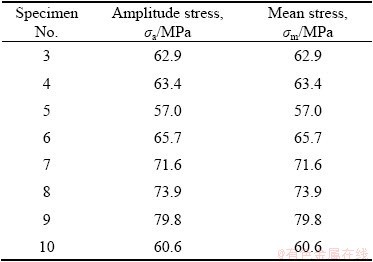
Some data on the fatigue-life experiments of AM manufactured AlSi10Mg can already be found in Refs. [19,36,38,49-52]. Most of the researchers used cylindrical specimens and the high-cycle fatigue experiments were fully reversal (dynamic factor R=-1) [19,36,38,52]. Some researchers carried out pulsating fatigue-life experiments with R equal to 0 [51] or 0.1 [50]. In our case eight specimens were used for the high-cycle fatigue tests, because their number was limited. The loading was pulsating (R=0) in order to avoid buckling of the specimen due to its thin cross- section (Only eight specimens may not be enough if the loading levels were poorly chosen. However, the loading levels were not chosen in advance in our case, but were determined incrementally. This is because the data processing procedure, which is described in this section, allows for an arbitrary number of the loading levels as long as at least one specimen is tested at the selected loading levels). The tests were performed on the same 100 kN MTS Landmark hydraulic machine at room temperature of 23 ��C. The dynamic loading was force-controlled with the constant load cycle amplitude and mean values. The applied loading levels are listed in Table 2. The loading frequency was 25 Hz. The fatigue-life experiments were terminated after 4��106 loading cycles were reached to shorten the cumulative testing time. The result of each fatigue experiment is a number of repeated loading cycles to failure (N) at the tested stress level.
Table 2 Loading levels for high-cycle fatigue tests
Since each loading level was different the high-cycle fatigue-life curves for different failure probabilities were estimated using the approach of KLEMENC [53]. The fatigue-life curves are modelled with a conditional Weibull��s probability density function of the number of loading cycles to failure f(N|��max) at the stress level ��max:

 (1)
(1)
with the constant shape parameter �� and the scale parameter �� being the function of the maximum stress ��max according to the inverse power-law equation (the Basquin��s equation):
 (2)
(2)
��max=��m+��a (3)
where a0 and a1 are the intercept and slope of the Basquin��s curve in natural logarithm diagram, respectively.
Therefore, the scale parameter �� is not estimated individually for each loading level, but is linked to all the loading levels in the high-cycle fatigue domain through Eq. (2) with the two parameters a0 and a1 that need to be determined from the experimental data.
The three parameters a0, a1 and �� are estimated by minimising the negative value of a maximum likelihood cost function MLE (see KLEMENC [53]):

 (4)
(4)

 (5)
(5)
 (6)
(6)
where ��i is the characteristic parameter.
In this manner it is also possible to consider the specimens without the fatigue failure. The incomplete data (i.e. the run-out specimen(s) for which no fatigue failure occurred until 4��106 loading cycles) are considered in the MLE cost function from Eq. (4) via the second term and the parameter ��i. Consequently, the run-outs do not contribute to the MLE cost function through the probability density function, but through the corresponding cumulative probability function [54]. The rationale behind such modification of the MLE cost function is that the exact number of the loading cycles to failure N is not known for the run-out(s). However, it is known that such specimen(s) survived the censoring limit (i.e. 4��106 loading cycles) and could be considered by the cumulative probability function.
For minimising the negative value of the cost function in Eq. (4), the real-valued genetic algorithm (GA) and the differential ant-stigmergy algorithm (DASA) were applied. The details on the minimisation procedures using the two algorithms can be found in Ref. [55].
When a relatively small number of fatigue-life experiments are carried out to estimate the fatigue-life curve and its scatter (a significant uncertainty) is linked to the estimated S-N curves for arbitrary probability of rupture. So, it is necessary to estimate the corresponding confidence intervals at least for boundary S-N curves that are usually determined for 5% and 95% rupture probabilities. A Monte-Carlo simulation was applied for this purpose [56]. By following this approach, first 1000 data sets were composed using random sampling of eight data points {(��max_i , Ni); i=1, 2, ��, 8} from the estimated conditional Weibull��s probability density function f(N|��max) in the target domain of the maximum stress ��max. For each of these artificial data sets the parameters a0, a1 and �� were then estimated as described above and the values of the loading-cycles-to-failure N for 5% and 95% rupture probabilities were calculated. Finally, the lower confidence limit for the 5% probability of the fatigue failure and the upper confidence limit for the 95% probability of the fatigue failure were estimated at the 5% risk probability using the Weibull��s analysis. This means that for each of the equidistantly selected loading levels ��max in the target high-cycle fatigue domain a statistical distribution of the loading cycles N for 5% and 95% rupture probabilities was approximated with a separate Weibull��s distribution. The lower confidence limit for the 5% probability of rupture at every loading level is the value of N, below which 5% of the simulated data points were realized. This confidence limit was calculated from the approximated Weibull distributions for 5% rupture probability (At this point a remark should be made that the risk level of 5%, which is used for estimating the confidence interval, should not be confused with the 5% rupture probability. The latter is estimated directly from the experimental data and is data-dependent. On the other hand, the confidence limit for 5% of risk is determined using Monte-Carlo simulations. It depends on the original parameters a0, a1, �� and the methodology for estimating the S-N curve). In analogy to fact that the upper confidence limit for the 95% probability of rupture at every loading level is the value of N, 5% of the simulated data points were realised.
3 Results and discussion
3.1 Microstructure
Figure 3 shows a light micrograph of the polished surface of Specimen 1 after SLM. The black circles represent porosity. The pores were much more frequent and also much larger near the specimen surface around the whole circumference, up to 500 ��m inwards. The diameters of the largest pores were (47��16) ��m, and their distances to the surface were (192��142) ��m. These near-surface pores were formed at the end/beginning of a scan vector in the x-direction. The laser movement in the y-direction did not remove them during the formation of the subsequent layer. Some larger pores were also inside the specimens. However, their typical sizes were much smaller (10-20 ��m), and they were visible at higher magnifications.
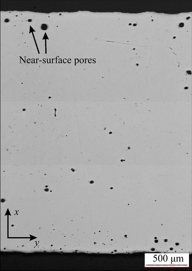
Fig. 3 Light micrograph of polished surface of Specimen 1 in x-y plane showing distribution of pores (Deposition direction z is perpendicular to micrograph)
Figure 4 shows a light micrograph of etched Specimen 1 after SLM. The arrows indicate subsequent layers formed by the laser beam, when it scanned in the x-direction (perpendicular to the micrograph). The lateral movement in the next x-layer was opposite to the previous one. It is evident that the microstructure consists of bands, which were produced by varying the scan direction in each subsequent layer. The y-layers were nearly continuous on this cross-section, since the laser beam moved uniformly from the left to the right and vice versa. The x-direction was perpendicular to the metallographic surface. Each laser pass caused partial remelting of the bottom y-layer and a neighbouring lateral x-trace. Thus, the microstructure revealed clearly the sequence of deposition. The passing laser beam caused full remelting of the initial powder, and partial remelting of the bottom layer and the neighbouring trace in the same layer. Some of the previously solidified material remelted fully and some areas were heated to two-phase ��(Al) + liquid regions. These two-phase regions are brighter, and separate areas are produced by each scan of the beam.

Fig. 4 Light micrograph of etched Specimen 1 (Building direction is z-axis)
Figure 5 shows the microstructure of the etched Specimen 1 at a higher magnification. The fully remelted areas consisted of dendritic cells growing in direction opposite to the prevalent heat extraction, while the dendrites in the partly remelted zone were larger since they were able to coarsen, when they were in the contact with the melt.
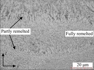
Fig. 5 Light micrograph of etched Specimen 1 at higher magnification
In the fully remelted areas, the ��-Si particles were between the dendritic cells as individual particles (Fig. 6(a)). The interdendritic spaces in the mushy zone were larger (1 ��m), and in this region very fine coral-like eutectic ��-Si was present as a part of ��(Al) + ��-Si eutectic, which is considerably smaller than that in castings (Fig. 6(b)). Some ��-Si particles were present within the dendrites. Previous studies showed that approximately 9% Si was dissolved in ��(Al) [57], which significantly exceeded the maximum equilibrium solubility of Si in Al.
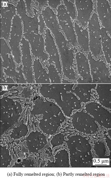
Fig. 6 Secondary electron micrographs of microstructure
3.2 Quasi-static test results
3.2.1 ��-�� curve
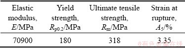
The measured quasi-static ��-�� responses for Specimens 1 and 2 are shown in Fig. 7. It can be concluded that the agreement between the measured ��-�� diagrams is almost perfect with an exception of the strain at rupture. Through the whole domain the discrepancy between the two curves is less than 2 MPa. The average measured values for the typical material parameters are presented in Table 3.

Fig. 7 ��-�� responses from tensile tests
Table 3 Average measured material parameters of SLM AlSi10Mg alloy
When compared to the literature the two measured characteristics are in the scatter band of the reported results, but the strain at rupture in our case is approximately half the value of strain at rupture given in Ref. [36]. The two measured ��-�� responses are also consistent with other data from Refs. [51,58].
The results obtained by quasi-static tests served as a basis for the determination of loading level of further fatigue tests. Here, the highest maximum stress level of 159.6 MPa, which represents the end of the linear elastic characteristic in ��-�� response and the smallest maximum stress of 114 MPa (approximately 66% smaller than the ultimate tensile strength) were chosen for that purpose.
3.2.2 Fractography of tensile specimens

Fig. 8 Secondary electron micrograph of fracture surface of Specimen 1

Fig. 9 Secondary electron micrographs of fracture surface of Specimen 1 corresponding to Regions A (a) and B (b) in Fig. 8
The fracture surfaces of both specimens were similar. Figures 8 and 9 show the fracture surface of the tensile Specimen 1. The fracture probably started near the surface, at the sites, where large pores were present. Although the contraction of the specimen was small, the fracture surface showed characteristics of a ductile fracture, with many dimples. Some dimples were 10-20 ��m in diameter, others were 4-7 ��m and most of them were 0.5-2 ��m. Some of the largest dimples perhaps belong to the pores that were initially present in the microstructure. Smaller dimples formed during the plastic deformation. The dislocation glide can cause the decohesion at the matrix-particle interface or fracture of particles, resulting in the formation of microvoids. The microvoids grew and coalesced during further plastic deformation until they were torn apart. 3.3 Fatigue behavior
3.3.1 Fatigue life
The results of the eight fatigue-life experiments together with the fatigue-life curves for 5%, 50% and 95% probabilities of fatigue failure, which were determined by inserting the estimated parameters a0, a1 and �� into Eq. (5), and the corresponding confidence intervals are presented in Fig. 10. Although the transition between the high- cycle and ultra-high-cycle fatigue domains for aluminium alloys is considered to be at 1��107 loading cycles, we stretched our S-N curve for 50% rupture probability until 2��107 loading cycles. The purpose of that was to clearly present how the confidence intervals are expanded at the boundaries of the experimental data. The estimated parameters a0, a1 and �� are presented in Table 4. These are the best estimates from 10 runs of both minimization algorithms, i.e. the estimates that correspond to the smallest value of the negative MLE cost function from Eq. (4). Each repetition run from both algorithms was always terminated after 1��104 iterations, because no significant change of the MLE cost function was achieved between 1��103 and 1��104 iterations. The estimates from the real-valued genetic algorithm were consistently better than those from the ant-stigmergy algorithm. This means that in 10 repetitions of each optimization algorithm the real-valued genetic algorithm found the smallest value of the negative MLE cost function. Besides, an average value and a standard deviation of the negative MLE cost function from 10 repetition runs were also smaller for the genetic algorithm. Last, but not least, the genetic algorithm always converged to the global minimum of the negative cost function, while the ant-stigmergy algorithm was caught in the local minimum of the negative cost function during one repetition run.
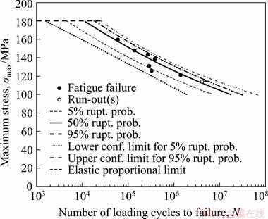
Fig. 10 Results of fatigue-life experiments with corresponding fatigue-life curves
Table 4 Best estimates for a0, a1 and �� parameters of SLM AlSi10Mg alloy and their typical values from Monte-Carlo (MC) simulations for confidence- interval estimations

If the scatter of experimental results in Fig. 10 is compared with that in Fig. 7, it can be concluded that the scatter of the fatigue-life is much higher than that of the static durability. It can be seen that there is one outlier in Fig. 10, i.e. the result at ��max level of 125.8 MPa, which influences the scatter a lot. However, no macro-geometrical inhomogeneity was found at the rupture spot of this specimen and no peculiarities occurred during the experiment. For this reason, it was included in the minimisation process for estimating a0, a1 and ��. The value 2.8916 for the �� parameter in Table 4 indicates a significant spread of the experimental data, which spans approximately over an order of magnitude along the abscissa axis in the high-cycle fatigue domain. Such scatter is a consequence of the specimen��s manufacturing process (see also explanation in Section 3.3.2).
The scatter bands of the loading-cycles-to- failure in Fig. 10 were determined with a help of Eqs. (2), (3) and (5). The S-N curves for 5%, 50% and 95% rupture probabilities were calculated using the estimated parameters from the first line of Table 4. A comparison of the high-cycle fatigue data with the data from the literature is rather difficult, because only two research results were reported for the pulsating loads R��0 [50,51]. Most of the data from the literature were obtained for the fully-reversal loading R=-1 [19,36,38,52]. It can be concluded that the scatter of our data is of the same level as that for the data in Refs. [50,51], i.e. it spans approximately one order of magnitude in the direction of the loading-cycles-to-failure N. It can also be concluded that our experimental data points for the pulsating loading (R=0) are in the same domain as the data from Refs. [50,51] for the comparable heat treatment, despite different specimen geometries. This confirms the validity of our results, when taking into account the characteristics of the AM process.
Due to the relatively high scatter of the fatigue lives and the small number of tested specimens the width of the confidence interval between its lower limit for the 5% probability of the fatigue failure and the upper limit for the 95% probability of the fatigue failure is relatively high. It spans a width of 1.2 decade at the end of the modelled fatigue-life curves and 1 decade in the middle of the modelled fatigue-life curves. The average values and standard deviations of the three parameters a0, a1 and �� that were calculated from the Monte-Carlo simulations are listed in Table 4. These values are consistent with the estimated parameters in second column of Table 4. The highest discrepancy is for the shape parameter ��, which is common for the sample set that consists only of 8 sample points. The width of the confidence interval cannot be compared with the data from the literature, since the researches have not reported it in any published work.
3.3.2 Fractography of fatigue specimens
Figure 11 shows the secondary electron micrograph of a typical fatigue fracture surface (white arrows indicate the crack propagation direction during the stable crack growth). It can be seen that the fracture surface consists of four regions: the region of fatigue striations (FS) close to the surface, the region of stable crack growth (S), the region of unstable crack propagation (I) and the region of forced fracture (FF).
Figure 12(a) shows a region between the original SLM-surface and fracture surface. The original surface was rather rough, with many surface defects (Fig. 12(b)). Cracks formed at several sites, and some of them grew from the surface inwards. At the beginning fatigue striations can be seen. They were typical features during crack growth at rather low stress intensity factor. This type of crack growth was limited to a near-surface region. As stress intensity factor increased, the stress concentration around large surface defect caused unstable crack propagation in all directions. In this stage of crack growth, the surface contained several flat surfaces, i.e. facets.

Fig. 11 Secondary electron micrograph of fatigue fracture of Specimen 9
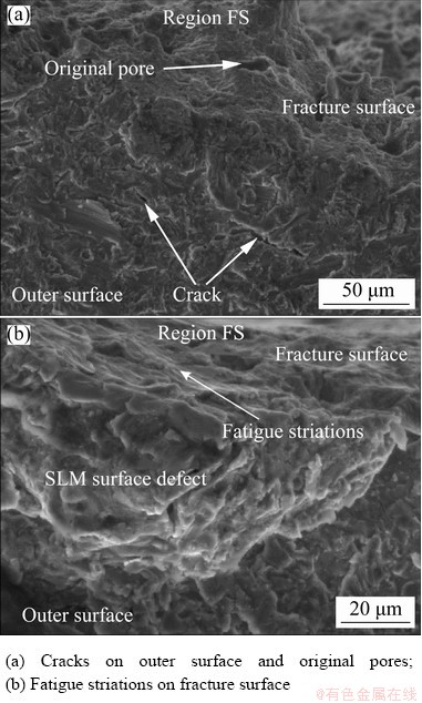
Fig. 12 Secondary electron micrographs of fatigue fracture of Specimen 9 in Region FS in Fig. 11
The pores shown in Fig. 13 formed during the SLM process rather than during the crack propagation. The fracture surface was not completely flat due to a fine microstructure consisting of ��(Al) and ��-Si. During the stable crack propagation, plastic deformation occurred at the crack tip, producing pores of different sizes (Fig. 14). At this stage the crack propagation speed away from the region of unstable growth was much faster than the growth speed of the surface with fatigue striations. Such a growth is typical for high stress intensity factor, when the stress is close to the yield point of the alloy.
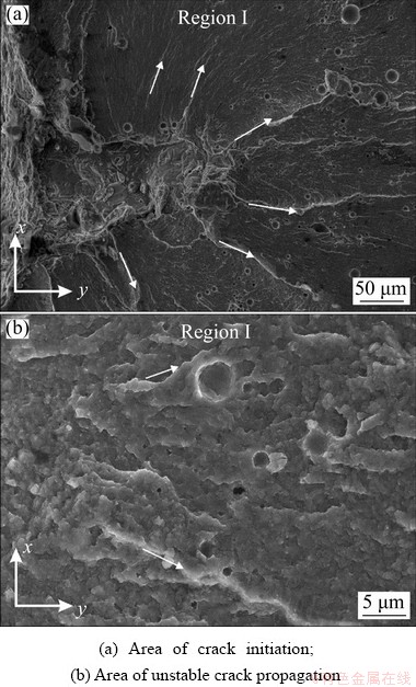
Fig. 13 Secondary electron micrographs of fatigue fracture of Specimen 9 in Region I of unstable crack propagation in Fig. 11

Fig. 14 Secondary electron micrographs of fatigue fracture of Specimen 9 in Region S of stable crack propagation in Fig. 11
4 Conclusions
(1) The microstructure of treated SLM AlSi10Mg alloy consists of bands, which were produced by varying the scan direction in each subsequent layer. The material porosity is more frequent and larger in the near surface layers, where pores formed at the end/beginning of a scanning during the AM process.
(2) The obtained material parameters by quasi-static tests (proportional limit, ultimate tensile strength) are comparable to the results presented from other researches. The fractography of quasi-static specimens has shown that the fracture probably started near the surface, where large pores were present. The fracture surface showed characteristics of a tough fracture.
(3) The results of the fatigue experiments have shown that the scatter of the fatigue-life is much higher than that of the quasi-static durability, which is a consequence of the applied manufacturing process SLM. The fractography of fatigue specimens have shown that the fatigue cracks initiated around the surface defects, produced by SLM and then propagated in an unstable manner. However, the presence of large SLM defects mainly influenced the crack initiation period and did not have a strong influence on the crack propagation.
(4) The obtained experimental results serve as a basis for the further investigation of the fatigue behaviour of AM cellular structures made of treated SLM AlSi10Mg alloy.
Acknowledgments
The authors acknowledge the financial support of the research core funding (No. P2-0063) and the basic research project (No. J2-8186) from the Slovenian Research Agency.
Data availability
The raw/processed data required to reproduce these findings cannot be shared at this time as the data also form part of an ongoing study.
References
[1] Daniewicz S R, Shamsaei N. An introduction to the fatigue and fracture behavior of additive manufactured parts [J]. International Journal of Fatigue, 2017, 94: 167.
[2] ZHANG Q, LIANG Z F, CAO M, LIU Z F, ZHANG A F, LU B H. Microstructure and mechanical properties of Ti6Al4V alloy prepared by selective laser melting combined with precision forging [J]. Transactions of Nonferrous Metals Society of China, 2017, 27: 1036-1042.
[3] Simar A, Godet S, Watkons T R. Highlights of the special issue on metal additive manufacturing [J]. Materials Characterization, 2018, 143: 1-4.
[4] Herzog D, Seyda V, Wycisk E, Emmelmann C. Additive manufacturing of metals [J]. Acta Materialia, 2016, 117: 371-392.
[5] ISMAEEL A, WANG C S. Effect of Nb additions on microstructure and properties of ��-TiAl based alloys fabricated by selective laser melting [J]. Transactions of Nonferrous Metals Society of China, 2019, 29: 1007-1016.
[6] Bagherifard S, Beretta N, Monti S, Riccio M, Bandini M, Guagliano M. On the fatigue strength enhancement of additive manufactured AlSi10Mg parts by mechanical and thermal post-processing [J]. Materials and Design, 2018, 145: 28-41.
[7] Maskery I, Aboulkhair N T, Corfield M R, Tuck C, Clare A T, Leach R K, Wildman R D, Ashcroft IA, Hague R J M. Quantification and characterisation of porosity in selectively laser melted Al-Si10-Mg using X-ray computed tomography [J]. Materials Characterization, 2016, 111: 193-204.
[8] Aboulkhair N T, Tuck C, Ashcroft I, Maskery I, Everitt N M. On the precipitation hardening of selective laser melted AlSi10Mg [J]. Metallurgical and Materials Transactions A, 2015, 46: 3337-3341.
[9] Kempen K, Thijs L, van Humbeeck J, Kruth J P. Mechanical properties of AlSi10Mg produced by selective laser melting [J]. Physics Procedia, 2012 39: 439-446.
[10] Tan X, Kok Y, Tan Y J, Descoins M, Mangelinck D, Tor S B, Leong K F, Chua C K. Graded microstructure and mechanical properties of additive manufactured Ti-6Al-4V via electron beam melting [J]. Acta Materialia, 2015, 97: 1-16.
[11] Guan K, Wang Z, Gao M, Li X, Zeng X. Effects of processing parameters on tensile properties of selective laser melted 304 stainless steel [J]. Materials and Design, 2013, 50: 581-586.
[12] Thijs L, Montero S, Sistiaga M L, Wauthle R, Xie Q, Kruth J P, van Humbeeck J. Strong morphological and crystallographic texture and resulting yield strength anisotropy in selective laser melted tantalum [J]. Acta Materialia, 2013, 61: 4657-4668.
[13] Brice C, Shenoy R, Kral M, BUCHANNAN K. Precipitation behavior of aluminum alloy 2139 fabricated using additive manufacturing [J]. Materials Science and Engineering A, 2015, 648: 9-14.
[14] Zhou L, Mehta A, Schulz E, McWilliams B, Cho K, Sohn Y. Microstructure, precipitates and hardness of selectively laser melted AlSi10Mg alloy before and after heat treatment [J]. Materials Characterization, 2018, 143: 5-17.
[15] Wycisk E, Solbach A, Siddique S, Herzog D, Walther F, Emmelmann C. Effects of defects in laser additive manufactured Ti-6Al-4V on fatigue properties [J]. Physics Procedia, 2014, 56: 371-378.
[16] Beevers E, Brandao A D, Gumpinger J, Gschweitl M, Seyfert C, Hofbauer P, Rohr T, Ghidini T. Fatigue properties and material characteristics of additively manufactured AlSi10Mg��Effect of the contour parameter on the microstructure, density, residual stress, roughness and mechanical properties [J]. International Journal of Fatigue, 2018, 117: 148-162.
[17] Maconachie T, Leary M, Lozanovski B, Zhang X, Qian M, Faruque O, Brandt M. SLM lattice structures: Properties, performance, applications and challenges [J]. Materials and Design, 2019, 183: 108137.
[18] Siddique S, Muhammad I, Wycisk E, Emmelmann C, Walther F. Influence of process- induced microstructure and imperfections on mechanical properties of AlSi12 processed by selective laser melting [J]. Journal of Materials Processing Technology, 2015, 221: 205-213.
[19] Romano S, Br��ckner-Foit A, Brandao A, Gumpinger J, Ghidini T, Beretta S. Fatigue properties of AlSi10Mg obtained by additive manufacturing: Defect-based modelling and prediction of fatigue strength [J]. Engineering Fracture Mechanics, 2018, 187: 165-189.
[20] Lea V D, Pessarda E, Morela F, Edy F. Interpretation of the fatigue anisotropy of additively manufactured TA6V alloys via a fracture mechanics approach [J]. Engineering Fracture Mechanics, 2019, 214: 410-426.
[21] Leuders S, Thone M, Riemer A, Niendorf T, Troster T, Richard H A, Maier H J. On the mechanical behaviour of titanium alloy TiAl6V4 manufactured by selective laser melting: Fatigue resistance and crack growth performance [J]. International Journal of Fatigue, 2013, 48: 300-307.
[22] Fatemi A, Molaei R, Simsiriwong J, Sanaei N, Pegues J, Torries B, Phan N, Shamsaei N. Fatigue behaviour of additive manufactured materials: An overview of some recent experimental studies on Ti-6Al-4V considering various processing and loading direction effects [J]. Fatigue & Fracture of Engineering Materials & Structures, 2019, 42: 991-1009.
[23] Siddique S, Muhammad I, Rauer M, Kaloudis M, Wycisk E, Emmelmann C, Walther F. Computed tomography for characterization of fatigue performance of selective laser melted parts [J]. Materials & Design, 2015, 83: 661-669.
[24] Siddique S, Awd M, Tenkamp J, Walther F. Development of a stochastic approach for fatigue life prediction of AlSi12 alloy processed by selective laser melting [J]. Engineering Failure Analyses, 2017, 79: 34-50.
[25] Zhang C, Zhu H, Liao H, Cheng Y, Hu Z, Zeng X. Effect of heat treatments on fatigue property of selective laser melting AlSi10Mg [J]. International Journal of Fatigue, 2017, 94: 192-201.
[26] Tang M, Pistorius P C. Oxides, porosity and fatigue performance of AlSi10Mg parts produced by selective laser melting [J]. International Journal of Fatigue, 2018, 116: 513-522.
[27] Weingarten C, Buchbinder D, Pirch N, Meiners W, Wissenbach K, Poprawe R. Formation and reduction of hydrogen porosity during selective laser melting of AlSi10Mg [J]. Journal of Materials Processing Technology, 2015, 221: 112-120.
[28] Read N, Wang W, Essa K, Attallah M M. Selective laser melting of AlSi10Mg alloy: Process optimisation and mechanical properties development [J]. Materials & Design, 2015, 65: 417-424.
[29] Olakanmi E O, Cochrane R F, Dalgarno K W. A review on selective laser sintering/melting (SLS/SLM) of aluminium alloy powders: Processing, microstructure, and properties [J]. Progress in Materials Science, 2015, 74: 401-407.
[30] Boschetto A, Bottini L, Veniali F. Roughness modeling of AlSi10Mg parts fabricated by selective laser melting [J]. Journal of Materials Processing Technology, 2017, 241: 154-163.
[31] Calignano F, Manfredi D, Ambrosio E P, Iuliano L, Fino P. Influence of process parameters on surface roughness of aluminum parts produced by DMLS [J]. International Journal of Advanced Manufacturing Technology, 2013, 67: 2743-2751.
[32] Thijs L, Kempen K, Kruth J P, van Humbeeck J. Fine-structured aluminium products with controllable texture by selective laser melting of pre-alloyed AlSi10Mg powder [J]. Acta Materialia, 2013, 61: 1809-1819.
[33] Rosenthal I, Stern A, Frage N. Microstructure and mechanical properties of AlSi10Mg parts produced by the laser beam additive manufacturing (AM) technology [J]. Metallography, Microstructure, and Analysis, 2014, 3: 448-453.
[34] Tuck C, Aboulkhair N T, Maskery I, Ashcroft I, Everitt N M. On the formation of AlSi10Mg single tracks and layers in selective laser melting: Microstructure and nano-mechanical properties [J]. Journal of Materials Processing Technology, 2016, 230: 88-98.
[35] Manfredi D, Calignano F, Krishnan M, Canali R, Ambrosio E P, Atzeni E. From powders to dense metal parts: Characterization of a commercial AlSiMg alloy processed through direct metal laser sintering [J]. Materials, 2013, 6: 856-869.
[36] Ngnekoua J N D, Nadot Y, Henaff G, Nicolai J, Kan W H, Cairney J M, Ridosz L. Fatigue properties of AlSi10Mg produced by additive layer manufacturing [J]. International Journal of Fatigue, 2019, 119: 160-172.
[37] Awd M, Siddique S, Johannsen J, Emmelmann C, Walther F. Very high-cycle fatigue properties and microstructural damage mechanisms of selective laser melted AlSi10Mg alloy [J]. International Journal of Fatigue, 2019, 124: 55-69.
[38] Aboulkhair T, Maskery I, Tuck C, shcroft I A, Everitt N. Improving the fatigue behavior of a selective laser melted aluminum alloy: Influence of heat treatment and surface quality [J]. Materials & Design, 2016, 104: 174-182.
[39] Tang M, Pistorius C. Oxides, porosity and fatigue performance of AlSi10Mg parts produced by selective laser melting [J]. International Journal of Fatigue, 2017, 94: 192-201.
[40] Brandl E, Heckenberger U, Holzinger V, Buchbinder D. Additive manufactured AlSi10Mg samples using selective laser melting (SLM): Microstructure, high cycle fatigue, and fracture behavior [J]. Materials & Design, 2012, 34: 159-169.
[41] Uzan N, Ramati S, Shneck R, Nachum F, Yeheskel O. On the effect of shot-peening on fatigue resistance of AlSi10Mg specimens fabricated by additive manufacturing using selective laser melting (AM-SLM) [J]. Additive Manufacturing, 2018, 21: 458-464.
[42] Bagherifard S, Beretta N, Monti S, Riccio M, Bandini M, Guagliano M. On the fatigue strength enhancement of additively manufactured AlSi10Mg parts by mechanical and thermal post-processing [J]. Materials & Design, 2018, 145: 28-41.
[43] Wei P, Wei Z, Chen Z, Du J, He Y, Li J, Zhou Y. The AlSi10Mg samples produced by selective laser melting: Single track, densification, microstructure and mechanical behavior [J]. Applied Surface Science, 2017, 408: 38-50.
[44] Takata N, Kodaira H, Suzuki A, Kobashi M. Size dependence of microstructure of AlSi10Mg alloy fabricated by selective laser melting [J]. Materials Characterization, 2018, 143: 18-26.
[45] Lehmhus D, Vesenjak M, Schampheleire S D, Fiedler T. From stochastic foam to designed structure: Balancing cost and performance of cellular metals [J]. Materials, 2017, 10: 922.
[46] Novak N, Vesenjak M, Ren Z. Auxetic cellular materials��A review [J]. Journal of Mechanical Engineering, 2016, 62: 485-493.
[47] TomaZinCiC D, NeCemer B, Vesenjak M, Klemenc J. Low-cycle fatigue life of thin-plate auxetic cellular structures made from aluminium alloy 7075-T651 [J]. Fatigue & Fracture of Engineering Materials & Structures, 2019, 42: 1022-1036.
[48] NeCemer B, Vesenjak M, GlodeZ S. Fatigue of cellular materials��A review [J]. Journal of Mechanical Engineering, 2019, 65: 525-536.
[49] Beretta S, Romano S. A comparison of fatigue strength sensitivity to defects for materials manufactured by AM or traditional processes [J]. International Journal of Fatigue 2017, 94: 178-191.
[50] Hovig E W, Azar A S, Sunding M F, Sorby K, M'hamdi M, Andreassen E. High cycle fatigue life estimation of AlSi10Mg processed by laser powder bed fusion [C]//Proceedings of the 5th International Conference of Engineering against Failure (ICEAF-V2018). Chios Island, Greece, 2018.
[51] Bassoli E, Denti L, Comin A, Sola A, Tognoli E. Fatigue behavior of as-built L-PBF A357.0 parts [J]. Metals, 2018, 8: 634-646.
[52] Uzan N E, Shneck R, Yeheskel O, Frage N. Fatigue of AlSi10Mg specimens fabricated by additive manufacturing selective laser melting (AM-SLM) [J]. Materials Science and Engineering A, 2017, 704: 229-237.
[53] Klemenc J. Influence of fatigue-life data modelling on the estimated reliability of a structure subjected to a constant-amplitude loading [J] Reliability Engineering and System Safety, 2015, 142: 238-247.
[54] PASCUAL F G, MEEKER W Q. Estimating fatigue curves with the random fatigue-limit model [J]. Technometrics, 1999, 41(4): 277-290.
[55] Klemenc J, Fajdiga M. Joint estimation of E-N curves and their scatter using evolutionary algorithms [J]. International Journal of Fatigue, 2015, 6: 42-53.
[56] Klemenc J, Seruga D, Nagode M. A durability prediction for the magnesium alloy AZ31 based on plastic and total energy [J]. Metals, 2019, 9: 1-16.
[57] Li W, Li S, Zhang A, Zhiu Y, Wei Q, Yan C, Shi Y. Effect of heat treatment on AlSi10Mg alloy fabricated by selective laser melting: Microstructure evolution, mechanical properties and fracture mechanism [J]. Materials Science and Engineering A, 2016, 663: 116-125.
[58] Aboulkhair N T, Maskery I, Tuck C, Ashcroft I, Everitt N M. The microstructure and mechanical properties of selectively laser melted AlSi10Mg: The effect of a conventional T6-like heat treatment [J]. Materials Science and Engineering A, 2016, 667: 139-146.
S. GLODEZ1, J. KLEMENC2, F. ZUPANIC1, M. VESENJAK1
1. Faculty of Mechanical Engineering, University of Maribor, Smetanova 17, 2000 Maribor, Slovenia;
2. Faculty of Mechanical Engineering, University of Ljubljana, ASkerCeva 6, 1000 Ljubljana, Slovenia
ժ Ҫ���о�����ѡ���ۻ�(SLM) AlSi10Mg�Ͻ��ƣ�����ܺͶ�����Ϊ�������������غ�(R=0��RΪ��̬����)�£�����״����ֱ����Ƴ�ƣ������������״������Weibull���������ܶȺ�����ƣ��-����(S-N)���߽��н�ģ������ʵֵ�Ŵ��㷨(GA)�Ͳ����Ⱥ�㷨(DASA)���������Weibull������ƣ�������ĶϿ���ò������ƣ��������SLM��Ʒ�ı���ȱ����Χ���������Բ��ȶ��ķ�ʽ��չ��Ȼ���� SLM��ȱ�ݵĴ�����ҪӰ�������������ڣ���������չӰ�첻������ʵ������Ϊ��һ���о����������Ƚ����Ϻͽṹ(���Ԫ������)��ƣ����Ϊ�ṩ�������ر����ڶ�ά��Ԫ�ṹ�У���Ԫ�ṹ��Ľ���ͨ��Ϊ���Σ��뱾�о��е�������״���Ӧ��
�ؼ��ʣ�����ѡ���ۻ���AlSi10Mg�Ͻ𣻸���ƣ�ͣ�������Ϊ
(Edited by Wei-ping CHEN)
Corresponding author: S. GLODEZ; Tel: +386-2-2207708; Fax: +386-2-2207990; E-mail: srecko.glodez@um.si
DOI: 10.1016/S1003-6326(20)65403-6

