Optimization and experimental research on a new-type short cylindrical cup-shaped harmonic reducer
来源期刊:中南大学学报(英文版)2012年第7期
论文作者:高海波 庄红超 李志刚 邓宗全 丁亮 刘振
文章页码:1869 - 1882
Key words:harmonic drive; flexspline; structural parameter; multi-objective optimization
Abstract: In order to obtain a new-type short cylindrical cup-shaped flexspline that can be applied to space mechanisms, the APDL language of ANSYS software was employed to develop a parameterized equivalent contact model between a flexspline and a wave generator. The validity of the parameterized equivalent contact model was verified by comparing the results of the analytic value of the contact model and the value calculated by the theoretical formula. The curvilinear trend of stress was obtained by changing the structural parameter of the flexspline. Based on the curvilinear trend of stress, multi-objective optimizations of key structural parameters were achieved. Flexspline, wave generator, and circular spline of a new 32-type short cylindrical cup-shaped harmonic reducer were designed and manufactured. A performance test bench to carry out tests on the harmonic reducer was designed. Contrast experiments were implemented to determine the efficiency of the new 32-type short cylindrical cup-shaped harmonic reducer and the conventional 32-type harmonic reducer under different conditions. The experimental results reveal that there is approximately equality in terms of efficiency between the new 32-type short cylindrical cup-shaped harmonic reducer and the conventional 32-type harmonic reducer. The volume of the flexspline of the new 32-type short cylindrical cup-shaped harmonic reducer is reduced by approximately 30% through multi-objective optimization. When the new 32-type short cylindrical cup-shaped harmonic reducer is used on the wheel of a rover prototype, the mass of the wheel hub is decreased by 0.42 kg. Test analysis of wheel motion verifies that the new 32-type short cylindrical cup-shaped harmonic reducer can meet the requirements regarding bearing capacity and efficiency.
J. Cent. South Univ. (2012) 19: 1869-1882
DOI: 10.1007/s11771-012-1221-0![]()
GAO Hai-bo(高海波), ZHUANG Hong-chao(庄红超), LI Zhi-gang(李志刚),
DENG Zong-quan(邓宗全), DING Liang(丁亮), LIU Zhen(刘振)
State Key Laboratory of Robotics and System (Harbin Institute of Technology), Harbin 150001, China
? Central South University Press and Springer-Verlag Berlin Heidelberg 2012
Abstract: In order to obtain a new-type short cylindrical cup-shaped flexspline that can be applied to space mechanisms, the APDL language of ANSYS software was employed to develop a parameterized equivalent contact model between a flexspline and a wave generator. The validity of the parameterized equivalent contact model was verified by comparing the results of the analytic value of the contact model and the value calculated by the theoretical formula. The curvilinear trend of stress was obtained by changing the structural parameter of the flexspline. Based on the curvilinear trend of stress, multi-objective optimizations of key structural parameters were achieved. Flexspline, wave generator, and circular spline of a new 32-type short cylindrical cup-shaped harmonic reducer were designed and manufactured. A performance test bench to carry out tests on the harmonic reducer was designed. Contrast experiments were implemented to determine the efficiency of the new 32-type short cylindrical cup-shaped harmonic reducer and the conventional 32-type harmonic reducer under different conditions. The experimental results reveal that there is approximately equality in terms of efficiency between the new 32-type short cylindrical cup-shaped harmonic reducer and the conventional 32-type harmonic reducer. The volume of the flexspline of the new 32-type short cylindrical cup-shaped harmonic reducer is reduced by approximately 30% through multi-objective optimization. When the new 32-type short cylindrical cup-shaped harmonic reducer is used on the wheel of a rover prototype, the mass of the wheel hub is decreased by 0.42 kg. Test analysis of wheel motion verifies that the new 32-type short cylindrical cup-shaped harmonic reducer can meet the requirements regarding bearing capacity and efficiency.
Key words: harmonic drive; flexspline; structural parameter; multi-objective optimization
1 Introduction
The harmonic drive [1-4] has several characteristics. It features a high-speed reduction ratio with near zero backlash [5], excellent positioning accuracy and repeatability [6], low weight [7], compactness [8-9], high carrying capacity, high smoothness, multiple teeth contact and multizone gearing [10]. Because of the various significant advantages of the harmonic drive, it has been used in a wide range of precision products, such as industrial robots, machine tools, medical facilities [11], driving parts of measurement systems, semiconductor manufacturing systems [12], and space exploration equipment [13-14]. As can be seen in Fig. 1, the harmonic reducer is composed of three components: A wave generator, flexspline, and circular spline [12].
The harmonic drive is a new-type drive that depends on elastic deformation to achieve the goal of transmission [15]. Some researchers have conducted a great deal of research on harmonic reducers. Their research efforts have encompassed the principle of engagement, new gear form, flexspline fatigue strength, transmission accuracy, etc [16-17].
Although the harmonic drive has captured an increasing amount of research attention and has been widely applied over the last few decades, some problems related to drive technology remain that need to be resolved. Massive experimental data are required, especially on the research of flexspline. Generally, theoretical formulas are chosen to design harmonic reducers. Based on meeting the life span and efficiency requirements of harmonic reducers, a cup-shaped flexspline has been designed. However, the axial size of the cup-shaped flexspline is very large. The ratio of the axle to the diameter is approximately 1.0. Therefore, a large axial dimension in a cup-shaped flexspline is disadvantageous for a harmonic drive in a space mechanism.
In order to obtain a new-type short cylindrical cup-shaped flexspline that can be used in space mechanisms, multi-objective optimizations of the key structure parameters of the cup-shaped flexspline were carried out, based on stress sensitivity analysis of the cup-shaped flexspline in this work. On the basis of the multi-objective optimization results, a new-type short cylindrical cup-shaped harmonic reducer was designed and manufactured. Finally, efficiency experiments were implemented on a performance test bench. The new-type short cylindrical cup-shaped harmonic reducers were used on the wheel of a lunar rover prototype and tested on the wheel motion.
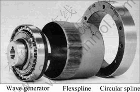
Fig. 1 Components of harmonic drive [12]
2 Influence of structural parameterized variation of flexspline on stress
2.1 Establishment and verification of parameterized equivalent contact model
When the finite element technique [18-20] is used to actualize the finite element contact analysis to different types of flexsplines and wave generators and the influence analysis coming from the changing of key structural parameters of a single flexspline to its maximum equivalent stress, a large number of iterations are required for calculation. Large-scale labor services are also needed for defining element type, meshing, imposing constrains and loads, and solution with building a new model every time. Therefore, it is greatly necessary to establish a parameterized equivalent contact model to automatically mesh and analyze for flexsplines and wave generators.
A large amount of work is also required to mesh and analyze a contact model with gear teeth [21]. As such, the wall thickness of gear teeth of a flexspline needs to be handled equivalently. Through this equivalent processing, the wall thickness of the gear ring is 1.186 4 times the thickness of a smooth ring at the tooth root. The flexspline is a symmetrical structure and bears symmetrical static loads. A quarter model of a flexspline can be established as a substitute for the entire model of the flexspline in analysis. Time can be saved on calculation and analysis in this manner [22-23].
The bottom-up modelling method was used to build a finite element model. The model was established from low-level primitive to high-level primitive. Namely, the line was created by points. The area was created by lines. The volume was created by areas. The bottom-up modeling method is easy to realize parametrization to one-quarter of the flexspline and wave generator. APDL language of the ANSYS software was chosen to compile the parameterized programs.
Based on the basic parameters researched, the three-dimensional model of a flexspline and wave generator with nonequivalent handling, which has gear teeth and the same parameters as the conventional 32-type harmonic reducer, was established by the Pro/E software. Meanwhile, the three-dimensional model was imported into the software of ANSYS. The operating method of the ANSYS software was progressively to define element type and material properties, mesh, create constrain loads and a couple of contacts (as shown in Fig. 2), and solve the model. Nephograms of the equivalent stress and displacement were obtained, as shown in Fig. 3.
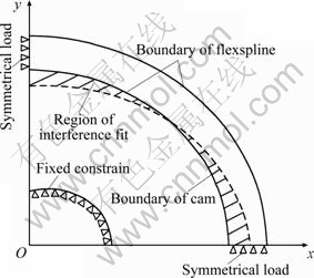
Fig. 2 Scheme of contact model of flexspline and wave generator
When the input operation of parameters was actualized through a program interface (as shown in Fig. 4), the 3-D equivalent contact model, meshing, equivalent stress, and displacement of a flexspline and wave generator of conventional 32-type harmonic reducer were respectively obtained, as shown in Fig. 5.
According to the analysis results from the model of the gear tooth, Fig. 3 shows that the maximum displacement of the flexspline with nonequivalent handling is 0.233 666 mm, and the maximum equivalent stress of the flexspline with nonequivalent handling is 319.241 MPa. Based on the analysis result of the parameterized equivalent contact model, Fig. 5 shows that the maximum displacement of the equivalent contact model of the flexspline is 0.252 727 mm, and the maximum equivalent stress of the equivalent contact model of the flexspline is 325.200 MPa. By comparing the analysis results between the nonequivalent handled contact model and the equivalent contact model, it is concluded that the relative error of the maximum displacement is 0.019 091 mm, and the relative error of the maximum equivalent stress is 5.959 MPa. The nephograms of the stress and displacement of the equivalent contact model are similar to those of the nonequivalently handled contact model. Comparing the conventional flexspline and wave generator thus verifies that the parameterized equivalent contact model of the flexspline and wave generator is accurate.
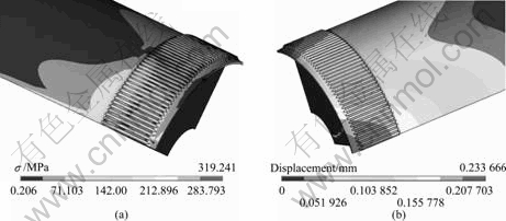
Fig. 3 Equivalent stress (a) and displacement (b) of model of flexspline and wave generator of conventional 32-type harmonic reducer with nonequivalent handling
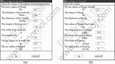
Fig. 4 Parameterized interface of equivalent contact model
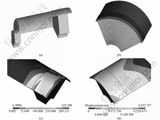
Fig. 5 3-D equivalent contact model (a), meshing (b), equivalent stress (c) and displacement (d) of flexspline and wave generator of conventional 32-type harmonic reducer with equivalent handling
Based on the third strength theory and ANSYS software, the maximum equivalent stresses of flexsplines of conventional 25-60 type harmonic reducers were respectively obtained by the theoretical formulas [24] and the finite element technique. A fitting curve of the maximum equivalent stress was gained, as depicted in Fig. 6.
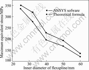
Fig. 6 Maximum equivalent stress curves of flexspline of conventional 25-60 type harmonic reducer
Figure 6 shows that the maximum equivalent stress of flexspline of conventional 32-type harmonic reducer is 277.512 MPa by calculating on the theoretic formulas, and it is smaller than the maximum equivalent stress of flexspline by analysis of ANSYS software. The main reason can be illustrated that the theoretical formulas were simplified and actualized types of hypothesis. Meanwhile, to revise correction factors of the theoretical formula is another important reason.
Figure 6 also shows that the maximum equivalent stress of flexspline gradually decreases with the augmentation of type of flexspline. In other words, the lower type harmonic reducer has shorter lifespan.
2.2 Influence of flexspline stress caused by structural parameterized variation
In order to actualize the optimized design to the geometric parameters of the flexspline, it is necessary to examine how the structural parameter of the flexspline affects the working performance. A flexspline is composed of smooth cylinder and tooth ring whose width is b. The wall thickness of flexspline contains the wall thickness of tooth ring and the wall thickness of the smooth cylinder. The smooth cylinder includes the front-end flange whose width is c and the back-end boss, as shown in Fig. 7.
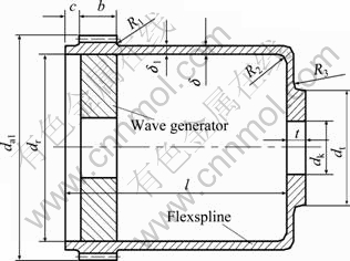
Fig. 7 Structural model of flexspline and wave generator
According to the structural characteristic of the flexspline and the numerical range of parameters, the main structural parameters were chosen. They mainly included the length of the cylinder of flexspline (l), the wall thickness of the tooth ring (δ1), the wall thickness of the smooth cylinder (δ), the tooth width (b), and the round radii of the flexspline (R1, R2, and R3).
2.2.1 Influence of length of cylinder of flexspline l
The length of the cylinder is one of the most important structural parameters for the flexspline. The influence of the length of the cylinder is very strong for the stress of the flexspline. The length range of the cylinder was set from 11 to 35 mm. When only the length of the cylinder was changed, a fitting curve was obtained, as depicted in Fig. 8.
Figure 8 illustrates that the maximum equivalent stress of the flexspline gradually decreases with length augmentation of the flexspline. When the length of the cylinder of the flexspline is fixed as 11-20 mm, that is, the length to diameter ratio of the flexspline is from 0.35 to 0.60, the maximum equivalent stress rate decreases. When the length of the cylinder of the flexspline is 20-25 mm, that is, the length to diameter ratio of the flexspline is from 0.60 to 0.80, the curvilinear trend of the maximum equivalent stress exhibits a slow drop. When the length of the cylinder of the flexspline lies in 11-20 mm range, that is, the length to diameter ratio of the flexspline is greater than 0.80, the maximum equivalent stress remains approximately constant. As such, according to Fig. 8, it can be concluded that the maximum stress of the smooth cylinder and the gear ring has a similar trend.
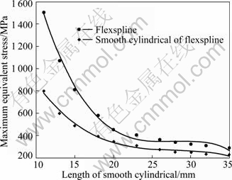
Fig. 8 Influence of length of cylinder on maximum equivalent stress
2.2.2 Influence of wall thickness of tooth ring δ1
The wall thickness of the tooth ring was set from 0.25 to 0.70 mm. When only the wall thickness of the tooth ring was changed, a fitting curve was obtained, as depicted in Fig. 9.
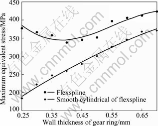
Fig. 9 Influence of wall thickness of gear ring on maximum equivalent stress
Figure 9 illustrates that the maximum equivalent stress of the flexspline is from decline to augmentation with the increase of wall thickness of the flexspline. The decline region of the maximum equivalent stress of flexspline is from 0.25 to 0.40 mm; the augmentation region of the maximum equivalent stress of flexspline is from 0.40 to 0.70 mm. The maximum equivalent stress of the smooth cylinder of the flexspline increases in an approximately linear manner with the increase of wall thickness of the tooth ring of flexspline.
2.2.3 Influence of wall thickness of smooth cylinder δ
The wall thickness of the smooth cylinder was set from 0.10 to 0.40 mm. When only the wall thickness of the smooth cylinder was changed, a fitting curve was obtained, as depicted in Fig. 10.
Figure 10 illustrates that the maximum equivalent stress of the flexspline is from decline to augmentation with the increase of wall thickness of smooth cylinder. The curve of the maximum equivalent stress of the flexspline is not smooth. The maximum equivalent stress of the smooth cylinder gradually decreases and its curve is very smooth.
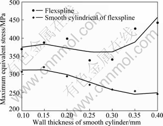
Fig. 10 Influence of wall thickness of smooth cylinder on maximum equivalent stress
2.2.4 Influence of tooth width b
The tooth width was set from 5 to 11 mm. When only the tooth width was changed, the fitting curve was obtained, as depicted in Fig. 11.
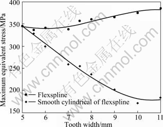
Fig. 11 Influence of tooth width on maximum equivalent stress
Figure 11 illustrates that the maximum equivalent stress of the flexspline is from decline to augmentation with the increase of tooth width. The maximum equivalent stress of the smooth cylinder gradually decreases with the tooth width from 5 to 10 mm. However, the curve of the maximum equivalent stress of the smooth cylinder keeps approximately a level, ranging from 10 to 11 mm. The reason for this can be illustrated as follows. When the tooth width increases, it is equivalent to reduce the length of the smooth cylinder. Namely, the rigidity of the smooth cylinder increases. Hence, the maximum equivalent stress of the smooth cylinder gradually decreases with the augmentation of tooth width.
2.2.5 Influence of round radius R1, R2 and R3
The round radii R1, R2, and R3 were respectively defined as 0.25-2.5 mm, 0.15-3 mm, and 0.15-2.5 mm.
When respectively changing only the round radius R1, R2, and R3, the fitting curves were obtained, as depicted in Figs. 12, 13 and 14.
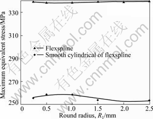
Fig. 12 Influence of round radius R1 on maximum equivalent stress
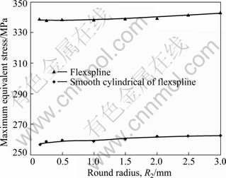
Fig. 13 Influence of round radius R2 on maximum equivalent stress
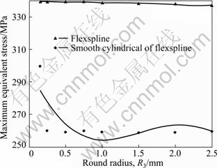
Fig. 14 Influence of round radius R3 on maximum equivalent stress
According to the results of the fitting curves of stress at different values of R1, R2, and R3, it can be deducted that the values of R1, R2, and R3 cause the small influence on the maximum equivalent stress of the flexspline. When only R1 was changed, the curvilinear trend of the maximum equivalent stress of the flexspline was from augmentation to decline. When only R2 was changed, the curvilinear trend of the maximum equivalent stress of the flexspline exhibited a gradual increase. When R3 was greater than 0.25 mm, the curvilinear trend of the maximum equivalent stress of the flexspline basically remained unchanged.
Similar results can be obtained for the 25-60 type harmonic reducer in accordance with the process mentioned above. Therefore, based on structural parameters of flexspline of conventional 32-type harmonic reducer, it is concluded that the influence on the maximum equivalent stress of the flexspline and the smooth cylinder is mainly derived from the length of the cylinder l, the wall thickness of the tooth ring δ1, the wall thickness of the smooth cylinder δ, and the tooth width b. The variation of the round radii R1, R2, and R3 have little influence on the maximum equivalent stress of the flexspline. The length of the cylinder is the main factor that influences the equivalent stress of the flexspline. When the length to diameter ratio of the flexspline exceeds 0.6, the variation of the maximum equivalent stress of the flexspline is very little.
The curvilinear trends of the maximum equivalent of stress, which are respectively caused by the variation of the wall thickness of the tooth ring and the wall thickness of the smooth cylinder, do not conform to the principle of monotonicity, and they are from decline to augmentation. When changing only the tooth width of the flexspline, the curvilinear trends are adverse between the maximum equivalent stress of the flexspline and the maximum equivalent stress of the smooth cylinder.
3 Multi-objective optimizations of short cylindrical cup-shaped flexspline
3.1 Mathematical model of multi-objective optimizations
3.1.1 Definition of design variables
According to the analysis of the main structural parameters of flexspline, design variables are defined. They are the modulus of the flexspline (m), the length of the cylinder (l), the wall thickness of the tooth ring (δ1), the wall thickness of the smooth cylinder (δ), and the tooth width (b). Thus, the variable function is written as follows:
![]() (1)
(1)
3.1.2 Establishment of objective functions
Under the condition of ensuring high fatigue life and carrying capacity equivalent of the conventional flexspline, the volume of the flexspline (V) and transmission efficiency (η) are respectively viewed as objective function f1(X) and f2(X) for multi-objective optimization.
The volume of the flexspline contains two parts: the gear ring and the smooth cylinder. The volume of the flexspline can be expressed as
![]()
![]() (2)
(2)
Then
![]()
![]() (3)
(3)
where dr is the bore size of the flexspline, ![]() is the addendum coefficient, c* is the tip clearance coefficient, and dm is the neutral circle diameter of the flexspline under nondeformation.
is the addendum coefficient, c* is the tip clearance coefficient, and dm is the neutral circle diameter of the flexspline under nondeformation.
Transmission efficiency η is written as [25]
![]() (4)
(4)
where ![]() and ηe is mesh efficiency; ηg is the efficiency of the wave generator, which includes ηg1 and ηg2;
and ηe is mesh efficiency; ηg is the efficiency of the wave generator, which includes ηg1 and ηg2; ![]() is the transmission ratio under the fixing wave generator; ηg1 is the efficiency of the wave generator bearing strain forces; ηg2 is the efficiency of the wave generator bearing an engaging force. Their equations are
is the transmission ratio under the fixing wave generator; ηg1 is the efficiency of the wave generator bearing strain forces; ηg2 is the efficiency of the wave generator bearing an engaging force. Their equations are
![]()

where η(H) is the efficiency of the transforming mechanism, λ is the correlation coefficient of the size distribution of the flexible bearing under the multi-load, ξ is the correlation coefficient of the rolling element distribution under the multi-load, pr1 is the radial load on the flexspline bearing, Tm is the input torque, ![]() is the transmission ratio under the fixing circular spline, α is the tooth profile angle, fs is the friction factor, z2 is the number of teeth of the circular spline, and r2 is the reference radius of the circular spline.
is the transmission ratio under the fixing circular spline, α is the tooth profile angle, fs is the friction factor, z2 is the number of teeth of the circular spline, and r2 is the reference radius of the circular spline.
Therefore, the objective function of efficiency is
![]() (5)
(5)
3.1.3 Constraint conditions
1) Constraint condition of fatigue strength
A method that checks the safety factor under two-directional stable-changed stress is chosen to calculate the fatigue strength. n is the safety factor. Thus,
![]() (6)
(6)
where np is the demand safety factor, γz is the parameter under the influence of axial stress σx, nσ is the safety factor under the condition of normal stress σ, and nτ is the safety factor under the condition of shear stress τ.
2) Constraint condition of carrying capacity
The output torque of the flexspline is defined as T0. The carrying capacity is regarded as T1. The condition is
![]()
Thus,
![]() (7)
(7)
where ε is the ratio of the total number of teeth in engagement, d1 is the reference diameter of the flexspline, hn is the maximum engaging-in depth, K is the loading coefficient, and pp is the allowable specific pressure [26].
3) Constraint condition of wall thickness of gear ring
Based on the requirement, the wall thickness of the gear ring is
![]() (8)
(8)
where d2 is the reference diameter of the circular spline, Kz is the coefficient of the number of working teeth, E is the material modulus of the elasticity of the flexspline, and Kp is the nonuniform coefficient of load distribution under the tooth space of running wheels. KF meets the requirement of the equation, namely, KF=(0.136 6z1- Kw)/Kw. Kw is the coefficient of deformation [27].
4) Constraint condition of bending strength
The bending strength of the flexspline should satisfy the constraint condition. Thus,
![]() (9)
(9)
where σFP is the allowable bending stress of the flexspline, and zy is the equivalent number of teeth.
5) Constraint condition of noinstability
The constraint condition of noinstability is
![]() (10)
(10)
![]()
where ν is the Poisson ratio of material, rm is the neutral circle diameter, and τT is the shear torque caused by torsional moment of the external load [27].
6) Constraint condition of wall thickness for smooth cylinder
The wall thickness of the smooth cylinder should meet the constraint condition. Thus,
![]() (11)
(11)
where Wt is the torsional section modulus.
7) Constraint condition of optimized design variables
The modulus of the flexspline (m) is a discrete value. The common useful value of the modulus contains 0.1, 0.15, 0.2, 0.25, 0.3, 0.4, 0.5, 0.6, 0.8 and 1.0. The wall thickness of the tooth ring (δ1) is constrained from 0.01d1 to 0.03d1. The tooth width of the flexspline (b) should meet the constrain conditions, which is 0.1d1≤b≤0.3d1. The length of the cylinder (l) is 0.5d1≤l≤1.2d1. The wall thickness of the smooth cylinder (δ) should satisfy 0.6δ1≤δ ≤0.9δ1.
3.2 Optimization example and results analysis
According to the characteristic of the mathematic model established above, the mathematic model is attributed to a nonlinear programming problem. As such, it can be solved by the multi-objective optimization function of fgoalattain in the MATLAB software.
The flexspline of the conventional 32-type harmonic reducer was optimized. A double-wave drive and cam wave generator were chosen for the harmonic drive. The value of the transmission ratio (i) was 80. 40CrNiMoA material was selected for the flexspline. The rated output torque was greater than or equal to 5.5 N・m. The input speed was required, and its value was not smaller than 1000 r/min. The input power was set at 12 W. The profile angle was 20°. According to the optimized model of the flexspline of the conventional 32-type harmonic reducer mentioned above, the correlation data of structural parameters between the front of the optimization and the end was obtained, as presented in Table 1.
Table 1 Correlation data of structural parameters of flexspline pre- and post-optimization
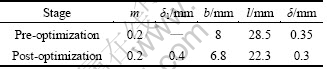
Table 1 reveals that the volume of the flexspline of the new 32-type short cylindrical cup-shaped harmonic reducer is reduced by approximately 30% through multi-objective optimization. The length of the cylinder of the flexspline becomes shorter than the front of the optimization, and the wall thickness of the flexspline becomes thinner than that of pre-optimization. The goal of the multi-objective optimization is realized under the precondition of satisfying the fatigue life and output torque for the conventional 32-type harmonic reducer.
4 Experimental research on short cylindrical cup-shaped harmonic reducer
4.1 Establishment of experimental sample
When the main structure parameters were determined, finite element analysis was carried out on the structures of three types of short cylindrical cup-shaped flexspline. Three types of bosses for short cylindrical cup-shaped flexsplines are shown in Fig. 15. Figure 15(a) shows that the entire boss is located at the internal flexspline. Figure 15(b) shows that half of the boss lies in the internal flexspline, and the other half of the boss is located in the external flexspline. Figure 15(c) shows that the entire boss is situated in the external flexspline.
ANSYS software was respectively employed to analyze the three types of bosses of the flexspline. When the entire boss is located at the internal flexspline, the equivalent stress and displacement of flexspline are obtained, as shown in Fig. 16. When the boss is uniformly distributed in the internal-and-external flexspline, the equivalent stress and displacement of flexspline are obtained, as shown in Fig. 17. When the entire boss is situated in the external flexspline, the equivalent stress and displacement of flexspline are obtained, as shown in Fig. 18.
According to the analysis result by the ANSYS software, the maximum equivalent stresses of the three types of short cylindrical cup-shaped flexsplines are approximately equal under the same load, whereas the maximum displacements of the three types of short cylindrical cup-shaped flexsplines are to some extent different. Through a respective comparison of analysis data of rigidity and intensity between the three types of short cylindrical cup-shaped flexsplines, it is demonstrated that the structure of the boss which is uniformly distributed in the internal-and-external flexspline (as shown in Fig. 15(b)) is the most reasonable.
Based on the multi-objective optimizations of the key structural parameters for flexspline, the most reasonable structure of the boss for the short cylindrical cup-shaped flexspline, and the most reasonable size of wave generator and circular spline by referring the theoretical formula, the experimental sample of the new 32-type short cylindrical cup-shaped harmonic reducer has been designed and manufactured, as shown in Fig. 19.
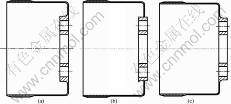
Fig. 15 Three types of bosses for short cylindrical cup-shaped flexsplines
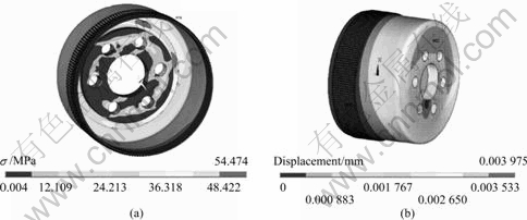
Fig. 16 Equivalent stress (a) and displacement (b) of flexspline with boss entirely located at internal flexspline
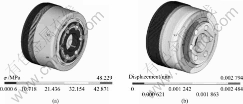
Fig. 17 Equivalent stress (a) and displacement (b) of flexspline with boss uniformly distributed in internal-and-external flexspline
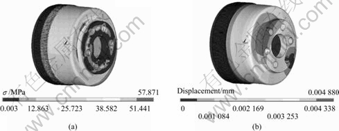
Fig. 18 Equivalent stress (a) and displacement (b) of flexspline with boss entirely located at external flexspline
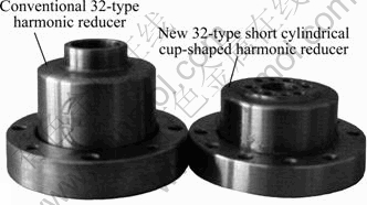
Fig. 19 Conventional 32-type harmonic reducer and new 32-type short cylindrical cup-shaped harmonic reducer
4.2 Design for performance test bench of harmonic reducer
In order to test the characteristic of the new 32-type short cylindrical cup-shaped harmonic reducer designed above, it is necessary to design and build a performance test bench that enables a comparison between the new 32-type short cylindrical cup-shaped harmonic reducer and the conventional 32-type harmonic reducer. The performance test bench can test the starting torque of the harmonic reducer, carrying capacity, overload capacity, efficiency, fatigue life, temperature rise, and so on.
If the input torque and output torque have been measured and the transmission ratio of the harmonic reducer has been obtained, then the transmission efficiency of the harmonic reducer can be determined. In this work, dynamic torque sensors, which are located at the two sides of the harmonic reducer, were used to test input torque and output torque. The value of torque was tested by data acquisition cards, and it was saved in the computer. A magnetic particle brake provided resistance moment. Junction boxes were widely used in links. The performance test bench is shown in Fig. 20.
4.3 Performance test of harmonic reducer
4.3.1 Test on no-load, load and temperature rise
1) No-load test
The performance test bench was set up. The wiring and the conjunction were checked in the test system. The running time of the electrical motor under the rated speed was set as 2 h in clockwise direction and 2 h in the anticlockwise direction. Abnormal noise and the mobile connecting piece were not found in the process of the test. Moreover, the test system exhibited stability, especially in terms of electric current.
2) Load test
When the new 32-type short cylindrical cup-shaped harmonic reducer which had been implemented after no-load test was chosen to have a rated speed to run, 50% and 100% of load were respectively loaded. The running time of the electrical motor under the rated speed was set as 2 h in the clockwise direction and 2 h in the anticlockwise direction. It was found that the test system exhibited stability, the connecting piece did not have mobility, and the sound of the test system was much bigger than that of the no-load test.
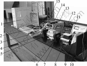
Fig. 20 Picture of performance test bench: 1-Computer; 2-24 V power; 3-Motor; 4-Base; 5-Motor supporter; 6-Component supporter of harmonic driver; 7-Components of harmonic driver; 8-Torque sensor; 9-Loader; 10-Loader supporter; 11-Controller of loader; 12-F/V converter and display meter; 13-DC regulated power supply; 14-Data acquisition card; 15-Motor driver
3) Temperature rise test
An infrared thermometer was used to detect the indoor temperature. The temperature of the region of engagement, which was located between the circular spline and the flexspline, was detected every 30 min. The test result of temperature rise was obtained, as presented in Table 2.
Table 2 Experimental data of temperature rise for harmonic reducer
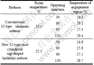
Based on the experimental data after 2 h, it is demonstrated that it is very small in the value of the temperature rise between the new 32-type short cylindrical cup-shaped harmonic reducer and the conventional 32-type harmonic reducer. The value of the temperature rise is approximately 7 ℃. This verifies that the new 32-type short cylindrical cup-shaped harmonic reducer satisfies the demand of slow temperature rise.
4.3.2 Test on efficiency
1) Comparative analysis of efficiency under same load and rated speed of electric motor
The input torque and output torque of the new 32-type short cylindrical cup-shaped harmonic reducer and the conventional 32-type harmonic reducer were respectively obtained under the same load and rated speed of electric motor. The curves of the torque were also determined, as respectively shown in Figs. 21 and 22. As such, the curves of efficiency were obtained between the new 32-type short cylindrical cup-shaped harmonic reducer and the conventional 32-type harmonic reducer, as depicted in Fig. 23.
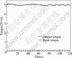
Fig. 21 Curves of torque for new 32-type short cylindrical cup-shaped harmonic reducer
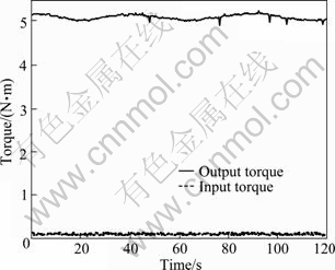
Fig. 22 Curves of torque for conventional 32-type harmonic reducer
According to Figs. 21 and 22, the curves of the output torque basically kept unchanged for the new 32-type short cylindrical cup-shaped harmonic reducer and the conventional 32-type harmonic reducer. The value of the output torque is from 4.95 to 5.15 N・m, and the value of input torque ranges from 0.07 to 0.085 N・m. Figure 23 reveals that the curve of efficiency of the new 32-type short cylindrical cup-shaped harmonic reducer displays much less fluctuation than that of the conventional 32-type harmonic reducer, and the average value of efficiency of the new 32-type short cylindrical cup-shaped harmonic reducer is 70%-80%.
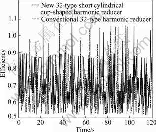
Fig. 23 Curves of efficiency between new 32-type short cylindrical cup-shaped harmonic reducer and conventional 32-type harmonic reducer under same load and rated speed of electric motor
2) Comparative analysis of efficiency under same speed
When the input speed was 218 r/min, the comparative experiment was actualized between the new 32-type short cylindrical cup-shaped harmonic reducer and the conventional 32-type harmonic reducer at different output torques. The experimental result is shown in Fig. 24.
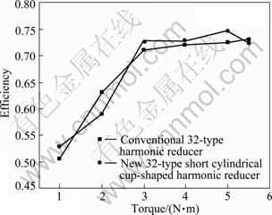
Fig. 24 Efficiency of new 32-type short cylindrical cup-shaped harmonic reducer and conventional 32-type harmonic reducer at different output torques
Figure 24 shows that the efficiency of the two types of harmonic reducers increases with the augmentation of output torque. The efficiency rapidly increases from 1 to 3 N・m. Then, the output torque is over 3 N・m; simultaneously, the increment of efficiency is small, and the value of efficiency is approximately 70%.
Figure 24 also shows that the curves of two types of harmonic reducers exhibit approximate coincidence. Therefore, this verifies that the new 32-type short cylindrical cup-shaped harmonic reducer is reasonable in terms of design, and it can achieve the requirements in efficiency.
3) Comparative analysis of efficiency under same load
When the output load was 5 N・m, the comparative experiment was actualized between the new 32-type short cylindrical cup-shaped harmonic reducer and the conventional 32-type harmonic reducer at different output speeds. The result of the experiment is depicted in Fig. 25.
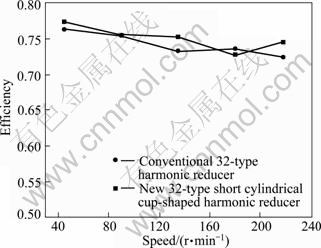
Fig. 25 Efficiency of new 32-type short cylindrical cup-shaped harmonic reducer and conventional 32-type harmonic reducer at different output speeds
Figure 25 shows that the variable quantity of efficiency of two types of harmonic reducers is not large when increasing input speed, which illustrates that the input speed is less than 1 000 r/min. However, the curvilinear trend of efficiency is descending, and the curves of two types of harmonic reducers exhibit approximate coincidence.
4.3.3 Test on overload and starting torque
Based on the no-load test and the load test to the harmonic reducer, the overload capacity was tested on the new 32-type short cylindrical cup-shaped harmonic reducer. Of course, different manufacturers have different criteria for the 32-type harmonic reducer in terms of the rated torque. Generally, the rated torque of a 32-type harmonic reducer is 5 N・m. As such, the overload quantity of torque was 10 N・m for the new 32-type short cylindrical cup-shaped harmonic reducer. The test time was 1 min. The experimental data show that the new 32-type short cylindrical cup-shaped harmonic reducer has more powerful capacity on overload, and the phenomenon of destruction of the new 32-type short cylindrical cup-shaped harmonic reducer is not found in the test (cracks, chip base, sliding tooth, etc).
The method of counterbalance was chosen to test the starting torque of the new 32-type short cylindrical cup-shaped harmonic reducer and the conventional 32-type harmonic reducer. The diameter of the cylinder of flexspline which coordinated with wave generator was 3 cm. The mass of counterbalance which met the requirement of the conventional 32-type harmonic reducer was approximately 40 g. The mass of counterbalance was approximately 50 g for the new 32-type short cylindrical cup-shaped harmonic reducer. The starting torque of the conventional 32-type harmonic reducer was 120 g・cm, and the starting torque was set as 150 g・cm for the new 32-type short cylindrical cup-shaped harmonic reducer. According to the test on starting torque, the starting torque of the new 32-type short cylindrical cup-shaped harmonic reducer is larger than that of the conventional 32-type harmonic reducer, but the new 32-type short cylindrical cup-shaped harmonic reducer meets the requirements for application.
5 Applications
The new 32-type short cylindrical cup-shaped harmonic reducer has the same carrying capacity and efficiency as the conventional 32-type harmonic reducer. Its length is approximately 70% that of the conventional 32-type harmonic reducer. Therefore, the new 32-type short cylindrical cup-shaped harmonic reducer has great potential for application in space mechanisms. The new 32-type short cylindrical cup-shaped harmonic reducers were used on the wheels of a lunar rover prototype. The wheel of lunar rover prototype is shown in Fig. 26.
In contrast with the mass of a wheel which had conventional 32-type harmonic reducer, the mass of the
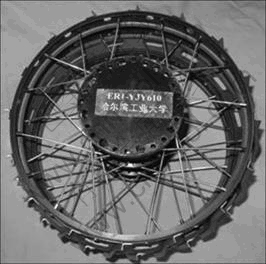
Fig. 26 Wheel installed with new 32-type short cylindrical cup-shaped harmonic reducer
wheel hub that had installed the new 32-type short cylindrical cup-shaped harmonic reducer decreased by 0.42 kg. This shows that using this new 32-type short cylindrical cup-shaped harmonic reducer in a space mechanism can reduce the mass of the mechanism. An experiment of wheel motion was actualized, as shown in Fig. 27. The experimental data reveal that the new 32-type short cylindrical cup-shaped harmonic reducer can meet the requirements related to bearing capacity and efficiency.
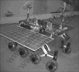
Fig. 27 Performance test of lunar rover prototype on motion
6 Conclusions
1) Based on the APDL language of the ANSYS software, parameterized equivalent contact models of a flexspline have been researched. Through comparing the results of the analytic value of the contact model and the value calculated by the theoretical formula, it is verified that they are valid parameterized equivalent contact models of a flexspline.
2) Taking the flexspline of a conventional 32-type harmonic reducer as an example analyzed by the finite element technique, the curvilinear trends of stress are obtained by changing the structural parameters of the flexspline. The results reveal that the influence on the maximum equivalent stress of the flexspline and the smooth cylinder is mainly derived from the length of the cylinder l, the wall thickness of the tooth ring δ1, the wall thickness of the smooth cylinder δ, and the tooth width b.
3) In order to design and manufacture a new-type short cylindrical cup-shaped flexspline, the volume of flexspline and the transmission efficiency are respectively taken as objective functions. The design variables of the flexspline include the modulus of the flexspline, cylinder length, wall thickness of the gear ring, wall thickness of the smooth cylinder, and tooth width. The constraint conditions are established for multi-objective optimizations of key structural parameters. The conventional 32-type harmonic reducer is chosen and utilized as an example for optimization. Through the optimization and analysis, it is found that the volume of the flexspline of the new 32-type short cylindrical cup-shaped harmonic reducer is reduced by approximately 30% through comparing with the conventional 32-type harmonic reducer.
4) According to the result of the optimization, the flexspline, wave generator, and circular spline of the new 32-type short cylindrical cup-shaped harmonic reducer are designed and manufactured. A performance test bench is designed to carry out testing on the harmonic reducer. Experiments are implemented to examine the differences in efficiency between the new 32-type short cylindrical cup-shaped harmonic reducer and the conventional 32-type harmonic reducer under different conditions. The experimental results reveal that they are approximately equal in terms of efficiency between the new 32-type short cylindrical cup-shaped harmonic reducer and the conventional 32-type harmonic reducer.
5) The new 32-type short cylindrical cup-shaped harmonic reducer is used on the wheel of a rover prototype. It is found that the mass of the wheel hub is decreased by 0.42 kg. The result of the experiment reveals that the new 32-type short cylindrical cup-shaped harmonic reducer can meet the requirements of bearing capacity and efficiency. This is determined by test analysis of wheel motion.
References
[1] MUSSER C W. Strain wave gearing. US 2906143[P]. 1959.
[2] GODLER I, HASHIMOTO M. Torque control of harmonic drive gears with built-in sensing[C]// Proceedings of the 24th Annual Conference of the IEEE Industrial Electronics Society, IECON. Aachen: IEEE Comp Soc, 1998: 1818-1823.
[3] GANDHI P S, GHORBEL F H, DABNEY J. Modeling, identification, and compensation of friction in harmonic drives [C]// 41st IEEE Conference on Decision and Control. Las Vegas, Nevada USA: Institute of Electrical and Electronics Engineers Inc, 2002: 160-166.
[4] TUTTLE T D. Understanding and modeling the behavior of a harmonic drive gear transmission [R]. Massachusetts: MIT Artificial Intelligence Laboratory, 1992.
[5] HAN C H, WANG C C, MASAYOSHI T. Suppression of vibration due to transmission error of harmonic drives using peak filter with acceleration feedback [C]// 10th International Workshop on Advanced Motion Control, AMC'08. Trento: Institute of Electrical and Electronics Engineers Inc, 2008: 182-187.
[6] SLATTER R, DEGEN R. Miniature zero-backlash gears and actuators for precision positioning applications [C]// 11th European Space Mechanisms and Tribology Symposium, ESMATS 2005. Lucerne, Switzerland: European Space Agency, 2005: 9-15.
[7] DHAOUADI R, GHORBEL F H, GANDHI P S. A new dynamic model of hysteresis in harmonic drives [J]. A IEEE Transactions on Industrial Electronics, 2003, 50(6): 1165-1171.
[8] DONG H, WANG D. Elastic deformation characteristic of the flexspline in harmonic drive [C]// ASME/IFToMM International Conference on Reconfigurable Mechanisms and Robots. London: IEEE Computer Society, 2009: 363-369.
[9] LI Gang-jun. Simulation of harmonic drive in precision robotic system [C]// 2010 Sixth International Conference on Natural Computation (ICNC 2010). Yantai, China: IEEE Computer Society, 2010: 4278-4281.
[10] CHEN Xiao-xia, LIN Shu-zhong, XING Jing-zhong. The investigation of elongation of the neutral line in harmonic drive [C]// 2010 International Conference on Computer Design and Applications (ICCDA 2010). Qinhuangdao, China: IEEE Computer Society, 2010: 383-386.
[11] GAO Wei, FURUKAWA M, KIYONO S, YAMAZAKI H. Cutting error measurement of flexspline gears of harmonic speed reducers using laser probes [J]. Precision Engineering, 2004, 28(3): 358-363.
[12] JEON H
[13] GAO Hai-bo, LI Zhi-gang, DENG Zong-quan. Sensitivity analysis of cup-shaped flexible gear parameters to its stress based on ANSYS [J]. Journal of Mechanical Engineering, 2010, 46(5): 1-7. (in Chinese)
[14] BAUMGARTNER E T, BONITZ R G, SHIRAISHI L R, MELKO J P, LEGER P C. The mars exploration rover instrument positioning system [C]// 2005 IEEE Aerospace Conference. Big Sky, Montana: Institute of Electrical and Electronics Engineers Computer Society, 2005: 1-19.
[15] ZHOU Hui, WEN Qing-ping, ZHANG Wei-wen. Harmonic drive used in spacecraft [J]. Vacuum & Cryogenics, 2004, 10(4): 187-192. (in Chinese)
[16] XIN Hong-bing, XIE Jin-rui, HE Hui-yang, ZHANG Zuo-mei. Harmonic drive technology and its research tendency [J]. Journal of Beijing Institute of Light Industry, 1999, 17(1): 30-36. (in Chinese)
[17] MAO Bin-bin, WANG Ke-wu. Research and development outlined of tooth profile of harmonic gear [J]. Coal Mine Machinery, 2008, 29(7): 6-8. (in Chinese)
[18] JIN Jun-song, XIA Ju-chen, WANG Xin-yun, Hu Guo-an, Liu Hua. Die design for cold precision forging of bevel gear based on finite element method [J]. Journal of Central South University of Technology, 2009, 16(4): 546-551.
[19] ZHUANG Hong-chao, WANG Jin-dong, WANG Ning, SHI Rong, LI Yan. Mechanical characteristic analysis of the magnetometer structure component for the space exploration [J]. Chin J Space Sci, 2011, 31(1): 112-117. (in Chinese)
[20] OSTAPSKI W, MUKHA I. Stress state analysis of harmonic drive elements by FEM [J]. Bulletin of the Polish Academy of Science, Technical Science, 2007, 55(1): 115-123.
[21] HE Jing-liang, WU Xu-tang, CUI Ya-hui, NIE Gang. Tooth contact analysis of conical involute gears [J]. Chinese Journal of Mechanical Engineering, 2006, 19(1): 105-108.
[22] XIN Hong-bing. Finite element analysis of stress on tooth rim of a flexspline [J]. Mechanical Science and Technology, 2003, 22(4): 558-559. (in Chinese)
[23] KAYABASI O, ERZINCANLI F. Shape optimization of tooth profile of a flexspline for a harmonic drive by finite element modeling [J]. Materials & Design, 2007, 28(2): 441-447.
[24] Gear Manual Edit Committee. Gear manual [M]. Beijing: China Machine Press, 2005: 9-12-9-13. (in Chinese)
[25] SHEN Yun-wen, YE Qing-tai. The theory and design of the harmonic gear drive [M]. Beijing: China Machine Press, 1985: 2-235. (in Chinese)
[26] RAO Zhen-gang. The design of planetary transmission mechanism [M]. Beijing: National Defense Industrial Press, 1994: 547-581. (in Chinese)
[27] YAN Yan-hong. Optimization design on structural dimensions of plastic harmonic gear drive [J]. Mechanical Design, 2002(10): 38-40. (in Chinese)
(Edited by YANG Bing)
Foundation item: Project(2010DFR70270) supported by the International Science and Technology Cooperation Project with Russia; Projects(50975059, 61005080) supported by the National Natural Science Foundation of China; Project(B07018) supported by “111” Program of China; Project(SKLRS200801A02) supported by the Foundation of State Key Laboratory of Robotics and System (Harbin Institute of Technology), China; Project(HIT2009061) supported by the Key Subject Laboratory Open Fund of China
Received date: 2011-07-26; Accepted date: 2011-11-14
Corresponding author: GAO Hai-bo, Professor, PhD; Tel: +86-451-86413857; E-mail: gaohaibo@hit.edu.cn, zhuangchao1026@sina.com

