电参数及其交互作用对铝材等离子体电解氧化膜的影响
来源期刊:中国有色金属学报(英文版)2020年第4期
论文作者:安凌云 马颖 剡晓旭 王晟 王占营
文章页码:883 - 895
关键词:铝;等离子体电解氧化;电压;频率;占空比;交互作用;正交实验;耐蚀性能
Key words:aluminum; plasma electrolytic oxidation; voltage; frequency; duty ratio; interaction; orthogonal experiments; corrosion resistance
摘 要:在碱性硅酸盐体系中对纯铝进行等离子体电解氧化处理。采用正交实验研究电压、频率、占空比及其交互作用对等离子体电解氧化膜层厚度和耐蚀性能的影响。通过Image J软件测量膜层截面以获得膜层厚度,并分别采用点滴和电化学实验评价膜层在HNO3和NaCl介质中的耐蚀性能。结果表明,本研究实验设计是研究电参数间交互作用的关键所在。各电参数不仅独立地影响膜层,而且其交互作用也显著影响膜层。高电压、低频率和大占空比间的交互作用使膜层厚度和耐蚀物相含量显著增加,进而改善膜层在HNO3腐蚀介质中的耐蚀性能;反之,低电压、高频率和小占空比间的交互作用使膜层最为致密,膜层在NaCl腐蚀介质中的耐蚀性最佳。
Abstract: Based on orthogonal experiments, the effects of voltage, frequency, duty ratio and their interactions on the thickness and corrosion resistance of coatings prepared by plasma electrolytic oxidation (PEO) on aluminum in an alkaline silicate-containing electrolyte were investigated. The thicknesses of these coatings were obtained by measuring their cross-section using Image J software. Their corrosion resistances were evaluated in HCl and NaCl media through spot test and electrochemical test. The results show that the experimental design of this study is the key to investigate the interactions among these electrical parameters. Additionally, not only each independent factor, but also their interactions exhibit a remarkable influence on the coatings. The combination of high voltage, low frequency and large duty ratio significantly increases the coating thickness and content of the corrosion resistance phase, and thus improves the corrosion resistance of the coating in HNO3 medium. Conversely, the coating possessing the densest microstructure and best corrosion resistance in NaCl medium is obtained when low voltage and high frequency match with a small duty ratio.
Trans. Nonferrous Met. Soc. China 30(2020) 883-895
Ling-yun AN, Ying MA, Xiao-xu YAN, Sheng WANG, Zhan-ying WANG
State Key Laboratory of Advanced Processing and Recycling of Nonferrous Metals, Lanzhou University of Technology, Lanzhou 730050, China
Received 18 July 2019; accepted 16 March 2020
Abstract: Based on orthogonal experiments, the effects of voltage, frequency, duty ratio and their interactions on the thickness and corrosion resistance of coatings prepared by plasma electrolytic oxidation (PEO) on aluminum in an alkaline silicate-containing electrolyte were investigated. The thicknesses of these coatings were obtained by measuring their cross-section using Image J software. Their corrosion resistances were evaluated in HCl and NaCl media through spot test and electrochemical test. The results show that the experimental design of this study is the key to investigate the interactions among these electrical parameters. Additionally, not only each independent factor, but also their interactions exhibit a remarkable influence on the coatings. The combination of high voltage, low frequency and large duty ratio significantly increases the coating thickness and content of the corrosion resistance phase, and thus improves the corrosion resistance of the coating in HNO3 medium. Conversely, the coating possessing the densest microstructure and best corrosion resistance in NaCl medium is obtained when low voltage and high frequency match with a small duty ratio.
Key words: aluminum; plasma electrolytic oxidation; voltage; frequency; duty ratio; interaction; orthogonal experiments; corrosion resistance
1 Introduction
Aluminum and its alloys are widely used in the domains of machinery, electronics, textile and aerospace due to their excellent properties, such as low density, high specific strength, good toughness and excellent machinability. Unfortunately, they are susceptible to corrosion, which significantly restricts their further application, especially in extreme service conditions [1,2]. Therefore, it is necessary to modify the surface of aluminum and its alloys to resist corrosion by adopting appropriate surface modification techniques including electro- chemical plating, chemical conversion, physical vapor deposition, laser cladding, anodic oxidation, and plasma electrolytic oxidation (PEO) [3,4]. Among them, PEO has been proven to be a novel and useful surface modification technique. It originates from traditional anodic oxidation and can be directly used to prepare ceramic-like coatings on the surface of aluminum, magnesium, titanium and their alloys. In addition, PEO is increasingly becoming popular owing to its simple operation, environmentally friendly electrolyte and the excellent wear and corrosion resistance of the obtained coatings [5-7].
The resultant PEO coatings can be controlled by a series of process parameters such as electrolyte, treatment time and electrical parameters including voltage, frequency, duty ratio and current density and so on. Among these, electrical parameters are the most important parameters [8-10].
The applied high voltage can lead to the occurrence of breakdown discharge during the PEO process, causing the obtained coating to differ from traditional anodic oxidation coating in essence. Thus, the voltage plays an extremely important role in PEO coating, and its influence has been studied in detail by several researchers [11-13]. For instance, LI et al [13] showed that with the increase of cathodic voltage, the growth rate of the coating was clearly enhanced and finally, the wear resistance of the coating was improved due to the thicker inner layer.
Regarding the frequency and duty ratio, researchers have inferred that they could modify the discharge characteristics of the coatings and thus, could improve their properties by adjusting the microstructure and thickness of the coatings [14-16]. EGORKIN et al [17] demonstrated that increasing the duty ratio resulted in augmentation of the coating thickness, elastic modulus and anti-wear property of the coatings. Additionally, ARUNNELLAIAPPAN et al [18] suggested that the coating formed at lower frequency (50 Hz) exhibited more pores and that prepared under a larger duty cycle (80%) showed more microcracks. In contrast, a higher frequency (1000 Hz) and a smaller duty cycle (20%) produced a smoother coating which possessed the most positive pitting potential, the highest polarization resistance and the best scratch resistance.
In addition, in our previous research [19], it has been found that, among the three electrical parameters including voltage, frequency and duty ratio, the voltage exhibits the greatest effect on coatings. With the rise of voltage, the coating thickness increases, and the corrosion resistance of the coatings is enhanced. Frequency and duty ratio have little effect on the coating thickness but exert a significant influence on the surface porosity and corrosion resistance of the coating.
However, the above studies on electrical parameters have mostly been carried out by adopting a single factor as the variable, and ignoring the influence of interactions among electrical parameters. In order to study the interactions among electrical parameters, the experimental design of this study is extremely important. Consequently, in this study, based on the orthogonal experimental design, the influence of voltage, frequency and duty ratio on the microstructure and corrosion resistance of PEO coatings was studied, with emphasis being placed on the effects of the interactions among electrical parameters. Additionally, the underlying influence mechanisms of the three factors and their interactions on the coatings were also explored.
2 Experimental
2.1 Materials and preparation of coatings
Pure aluminum specimens with dimensions of 30 mm × 20 mm × 10 mm were used as the substrate material in the experiments. Prior to the experiments, the specimen surfaces were successively ground using a series of SiC abrasive papers with four grades of 150, 400, 800 and 1200 grit, and then washed with distilled water and dried under normal atmospheric conditions. PEO treatment was performed by using a home-made pulsed power supply, and the specimen and stainless steel were used as anode and cathode, respectively. Samples were treated for 11 min under the constant voltage regime in the alkaline silicate electrolyte which was composed of 35 g/L Na2SiO3, 5 g/L NaOH and 5 g/L KF. During PEO process, the temperature of the electrolyte was maintained at 20 °C using a stirring and cooling system.
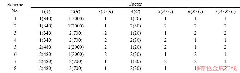
According to our previous research results [19], the electrical parameters including voltage (A), frequency (B) and duty ratio (C) were selected as three factors for this investigation. The orthogonal design table L8(27) was applied to studying the effects of voltage, frequency and duty ratio on the thicknesses and the corrosion resistances of the coatings, and more importantly to investigate the interactions among them (A×B, A×C, B×C, and A×B×C). Each factor and their levels are listed in Table 1. At the same time, the corresponding experimental schemes are listed in Table 2. In addition, the coating thickness, corrosion resistance in HNO3 medium and the corrosion current density in NaCl medium of the coatings were used as evaluation indexes, and their data were analyzed with the method of range analysis by using Excel software.
Table 1 Factors and levels of orthogonal experiments
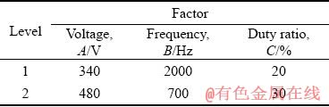
Table 2 Experimental schemes based on orthogonal design table L8(27)
2.2 Characterization of coatings
The surface and cross-section morphologies of PEO coatings were studied by field emission scanning electron microscope (FESEM). The thickness of the coating was obtained via measuring the thickness of its cross-section at 8 randomly selected positions on the obtained cross-section SEM images by using Image J software. Meanwhile, the distribution of the micropores as well as the porosity on the coating surface was also analyzed statistically on the obtained surface SEM images by Image J software. Phase composition of the coatings was detected by using a Rigaku D/MAX 2400 X-ray diffractometer (Cu Kα radiation), with a step size of 0.02° in the range from 20° to 80°.
The corrosion resistance of the coatings in HNO3 medium was evaluated by the spot test in accordance with HB5061-77 standard, but the concentration of HNO3 was doubled [20], namely, HNO3 corrosive medium was composed of 10 mL of HNO3, 0.05 g of KMnO4 and 90 mL of deionized water. Two drops of the purple corrosive liquid were dropped on the selected area of both the front and back of 4 samples, recording the needed time that the corrosive medium completely changed into the colorless, and the longer the needed time was, the better the corrosion resistance of the samples was. It should be pointed out that the needed time is described as corrosion resistance (min) in this study.
The CHI660 electrochemical workstation was used to study corrosion resistance of the coatings in the NaCl medium. A conventional three-electrode cell, with the coated samples as a working electrode (1 cm2 exposed area), the saturated calomel electrode (SCE) as a reference electrode, and the platinum electrode as a counter electrode, was utilized in the present study. The potentiodynamic polarization curve of samples was obtained at a scanning rate of 0.001 V/s in the range from -1.1 to -0.8 V after they were exposed to the neutral 3.5 wt.% NaCl corrosive medium for 30 min. According to the above mentioned operations, the potentiodynamic polarization tests were carried out at least 8 times at various locations of different samples.
Finally, the values of the thickness, corrosion resistance in HNO3 medium and the corrosion current density in NaCl medium of the coatings were all the average values, which were achieved after removing abnormal values from the original measured ones.
3 Results
3.1 Current-time responses
Figure 1 presents current-time responses of the PEO process for different orthogonal experiment schemes shown in Table 2. As can be observed from Fig. 1, current-time responses of different orthogonal experiment schemes have similar variation tendencies. Firstly, the current quickly increases and reaches the peak value after 2 min, and subsequently it decreases gradually until a stabilized value. At the same time, current shows a strong dependence on the voltage and duty ratio: current values under high voltage or large duty ratio are all higher than those under low voltage or small duty ratio. Additionally, the collocation of voltage and frequency clearly affects the current value, which is the highest during PEO when high voltage combines with low frequency.
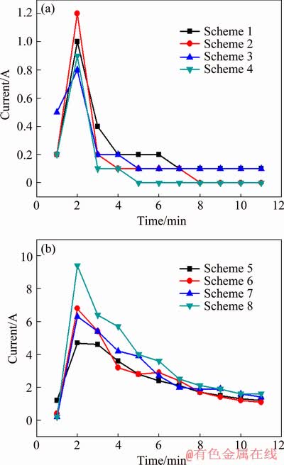
Fig. 1 Current-time responses during PEO process corresponding to Schemes 1-4 (a) and Schemes 5-8 (b) of orthogonal experiments
3.2 Orthogonal experimental results and analysis
Table 3 illustrates the thicknesses, corrosion resistances in HNO3 medium and the corrosion current densities (Jcorr) of the coatings prepared based on the orthogonal experiments. Among these three indexes, the Jcorr values of the coatings are obtained by fitting the potentiodynamic polarization curves shown in Fig. 2. It can be observed from Table 3 that the voltage exhibits the most significant effect on the thicknesses and corrosion resistances of the coatings. In the case of low voltage, the obtained coatings (Samples 1-4) are very thin, i.e. 2-4 μm. However, the coatings (Samples 5-8) prepared under high voltage are comparatively thicker with a thickness of 32-42 μm, which is approximately 10 times higher than that of the former coatings. The corrosion resistances of the coatings formed under low voltage are about 1/2 of those formed under high voltage in HNO3 medium, whereas their corrosion current densities are decreased by almost 87.5% compared to the latter.
Table 3 Results of orthogonal experiments (Samples 1-8 correspond to Schemes 1-8, respectively)
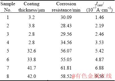
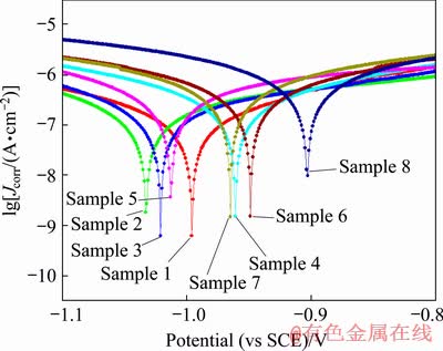
Fig. 2 Potentiodynamic polarization curves of PEO coatings obtained according to orthogonal experiment schemes
3.2.1 Range analysis
Orthogonal experimental data were analyzed by the method of range analysis, as listed in Table 4, in which k1 and k2 represent the mean values of experimental results at levels 1 and 2 of each factor, respectively; R is the difference between k1 and k2, and the greater the R is, the more important the factor is.
According to the R value, it is found that the decreasing influence of three factors and their interactions on coating thickness can be ranked as follows: voltage > interaction between voltage and frequency > frequency > duty ratio > interaction between frequency and duty ratio > interaction between voltage and duty ratio > interaction among voltage, frequency and duty ratio. The voltage has the greatest influence on coating thickness. At the same time, the effect of the interaction between voltage and frequency is the second only to voltage and greater than that of the independent factor of frequency.
Table 4 Results of range analysis of orthogonal experiments
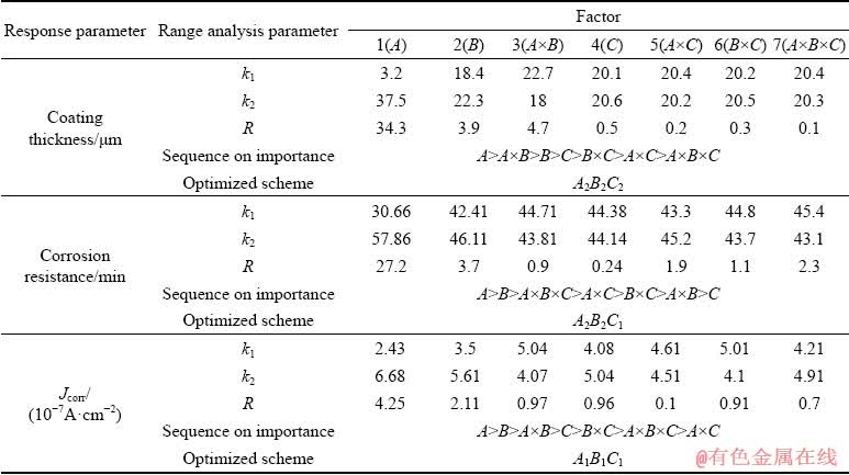
For the corrosion resistance of the coatings in HNO3 medium, the most important factor is the voltage, followed by frequency. The R value corresponding to voltage is 27.2, which improves by nearly one order of magnitude in comparison with that of the frequency. The influence of the interaction among the three factors is ranked the third, and its R value is only slightly lower than that of the frequency, but is still in the same order of magnitude as the frequency. Its R value is higher than those of the interactions between two factors including the interaction between voltage and duty ratio, interaction between frequency and duty ratio, and interaction between voltage and frequency. In addition, its R value is approximately 9 times that of the duty ratio. These suggest that the influence of the interaction among three factors is merely lower than the individual factor of voltage and frequency, and thus it plays an important role in improving the corrosion resistance of the coating in the HNO3 medium.
With regards to the corrosion resistance of the coatings in NaCl medium, the decreasing sequence of the influence of three factors and their interactions is: voltage, frequency, interaction between voltage and frequency, duty ratio, interaction between frequency and duty ratio, interaction among voltage, frequency and duty ratio, and interaction between voltage and duty ratio. Obviously, the factor of voltage is the most important, and its R value is approximately 2 times that of the frequency. Furthermore, compared with the factors including the interaction between voltage and frequency, duty ratio, and the interaction between frequency and duty ratio, the R value of the interaction among three factors is slightly lower. However, its R value is approximately one order of magnitude higher than that of the interaction between voltage and duty ratio. These indicate that the interaction among voltage, frequency and duty ratio has an obvious influence on the anti-corrosion property of the coating in NaCl medium.
3.2.2 Relationship between response indexes and electrical parameters
The relationships between the response parameters and electrical parameters including voltage, frequency, and duty ratio are presented in Fig. 3, which is drawn based on the values of k1 and k2 listed in Table 4. It can be observed from Fig. 3 that with the increase of the voltage, the coating thickness and the corrosion resistance in HNO3 medium are both improved, while its corrosion resistance in NaCl medium is deteriorated. Increasing the frequency is not beneficial to the increase of the coating thickness and corrosion resistance in HNO3 medium, but can enhance the corrosion resistance of the coatings in NaCl medium. When the duty ratio increases, the coating thickness increases slightly, and the corrosion resistance of the coating in HNO3 medium changes insignificantly, but its performance in anti-corrosion in NaCl medium decreases.
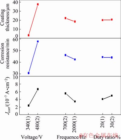
Fig. 3 Relationships between response indexes and electrical parameters
Apparently, optimal combinations among the three factors of electrical parameters for the thickness and corrosion resistances of coatings are different. Regarding the coating thickness, the best collocation scheme of the three factors is A2B2C2, namely high voltage, low frequency and large duty ratio. When high voltage and low frequency are matched with a small duty ratio (A2B2C1), the resultant coating possesses the strongest anti- corrosion ability in HNO3 medium. However, to obtain a coating with the optimum corrosion resistance in NaCl medium, the pure aluminum substrate should be treated by PEO under the condition of low voltage, high frequency and small duty ratio (A1B1C1).
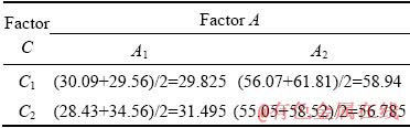
The results of the range analysis show that the interaction among three factors including voltage, frequency and duty ratio has an important influence on the corrosion resistance of the coating, and its influencing results are listed in Table 3. Unfortunately, it is difficult to illustrate intuitively the interaction effect among the three factors by virtue of a three-dimensional diagram. Here, taking the influence on the corrosion resistance of the coating in HNO3 medium as an example, the level matches and the corresponding interaction diagrams between two factors, namely, voltage and frequency, frequency and duty ratio, and voltage and duty ratio, are selected to reflect the interaction effect among the three factors, as shown in Tables 5-7 and Figs. 4-6.
Table 5 Level match of factor A and factor B for corrosion resistance of PEO coating in HNO3 medium (min)
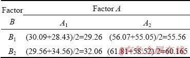
Table 6 Level match of factor B and factor C for corrosion resistance of PEO coating in HNO3 medium (min)
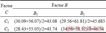
Table 7 Level match of factor A and factor C for corrosion resistance of PEO coating in HNO3 medium (min)
According to the orthogonal experiment results listed in Table 3, it is known that in the case of A2B2C1 i.e. high voltage, low frequency, and small duty ratio, the corrosion resistance of the coating in HNO3 medium is the best. This is consistent with the optimal scheme derived from Fig. 3. Likewise, for the coating thickness and corrosion resistance of the coating in NaCl medium, the optimum schemes obtained after considering the interaction among factors are in accordance with those in Fig. 3.
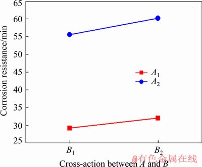
Fig. 4 Interaction between voltage (A) and frequency (B)
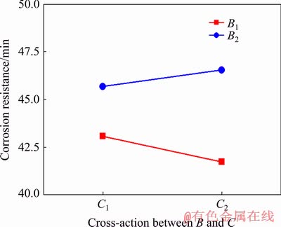
Fig. 5 Interaction between frequency (B) and duty ratio (C)
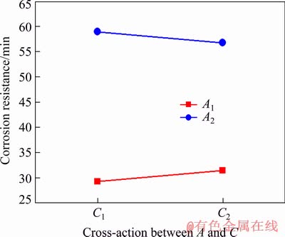
Fig. 6 Interaction between voltage (A) and duty ratio (C)
It can be summarized from the above analysis that the experimental design of this study is the key factor to research the interactions among electrical parameters. The orthogonal experimental design along with the method of range analysis can be utilized to study the influence of voltage, frequency and duty ratio on the coatings, and more importantly it can be used to investigate the interactions among these electrical parameters. At the same time, the interactions among these electrical parameters indicate that the coatings can be remarkably influenced not only by the individual factors of voltage, frequency, and duty ratio, but also their interactions.
3.3 Characterization of PEO coatings
3.3.1 Morphologies of surface and cross-section
Figure 7 displays the surface morphologies of the PEO coatings prepared on pure aluminum based on the orthogonal experiments. It can be observed from Fig. 7 that the influence of voltage on the surface morphologies of coatings is obvious. For the coatings (Samples 1-4) prepared under low voltage, the micropores are small and uniformly distributed on their surface. However, “gaps” left by abrasive paper grinding can be observed because of the low thickness and good copying ability of the coatings. In contrast, over the surface of the coatings (Samples 5-8) obtained in the case of high voltage, the “gaps” disappear, but molten particles are larger and the size of micropores increases significantly. Moreover, plenty of broad micro- cracks appear on the surface of the coatings formed under high voltage, and they connect with each other, which may decrease the corrosion resistance of the coatings.
Quantitative statistical results concerning the amount proportion of micropores with different sizes and porosities on the surface of the coatings prepared based on orthogonal experiments are depicted in Fig. 8. From Fig. 8(a), the surface of the coatings prepared under low voltage is nearly dominated by micropores with a dimension less than 1 μm; whereas, on the surface of the coatings formed under high voltage, the proportion of micropores having a diameter of 1-5 μm increases. Simultaneously, a few large-sized micropores (pore size >5 μm) appear and their proportion increases with the decrease of frequency or increase of duty ratio. As a result, the surface porosity of the coatings prepared under low voltage is clearly lower than that formed under high voltage. Furthermore, with decreasing the frequency or increasing the duty ratio, the surface porosity of the coating exhibits an increasing trend on the whole, as shown in Fig. 8(b).
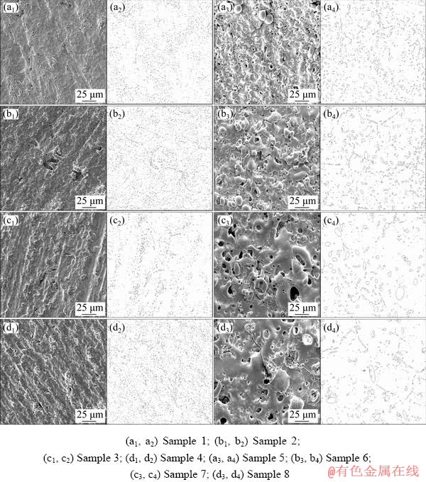
Fig. 7 Surface morphologies (a1-d1, a3-d3) and corresponding micropore distribution (a2-d2, a4-d4) of PEO coatings formed on pure aluminum based on orthogonal experiment schemes
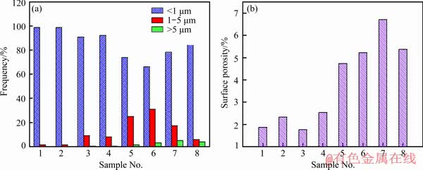
Fig. 8 Statistical results of micropore size distribution (a) and porosity (b) on surface of PEO coatings prepared based on orthogonal experiments
Figure 9 shows cross-sectional morphologies of the PEO coatings formed on pure aluminum according to the orthogonal experiments. It can be observed from Fig. 9 that the voltage has the largest influence on the cross-section morphologies of the coatings. The coatings (Samples 1-4) fabricated under low voltage only contain the dense layer, the thickness of which varies in the range of 2-4 μm, and there are almost no observable micropores and microcracks. The coatings (Samples 5-8) prepared in the condition of high voltage are mainly composed of an inner dense layer and an outer porous layer. The thickness of the dense layer is uneven, and many micropores as well as microcracks exist in the outer layer of the coating. Additionally, frequency and duty ratio have some influence on the cross-section morphologies of the coatings, especially in the case of high voltage. With the decrease of frequency or increase of duty ratio, the diameter of micropores in the outer layer of the coating increases, and thus the compactness of the coating declines.
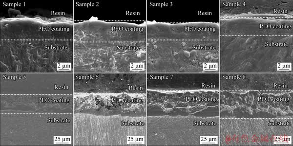
Fig. 9 Cross-sectional morphologies of PEO coatings formed on pure aluminum based on orthogonal experiments
3.3.2 Phase composition
Figure 10 shows the XRD patterns of the representative PEO coatings (Samples 2, 4, 6 and 8) prepared on pure aluminum based on the orthogonal experiments. The coatings of Samples 6 and 8 primarily consist of γ-Al2O3, mullite and a certain amount of amorphous phase which is demonstrated by the presence of wide diffraction peaks at 2θ of 15°-40°, while the coating of Sample 8 contains more mullite. In addition, the coating of Sample 8 also includes α-Al2O3. However, only Al originating from the substrate can be detected in the coatings of Samples 2 and 4, which may be due to the strong penetrating power of X-ray and very low content of the deposited phases.
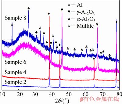
Fig. 10 XRD patterns of PEO coatings formed on pure aluminum
The PEO process contains a series of complex reactions. During this process, under the function of the strong electric fields, aluminum originating from the substrate is ionized into aluminum ions, which migrate into the discharge channels and react with oxygen ions, reactive oxygen and OH- ions to form Al2O3 (Eqs. (3) and (4)) and Al(OH)3 (Eq. (5)). Because Al(OH)3 is thermodynamically unstable, it is further dehydrated to Al2O3 under the high temperature caused by micro-arc breakdown (Eq. (6)) [21]. Research has suggested that γ-Al2O3 possesses lower nucleation free energy compared with α-Al2O3 [22], and hence, it can be formed more easily in the micro-arc discharge zone through rapid cooling of molten alumina when it contacts the surrounding cold electrolyte. However, the thermal stability of γ-Al2O3 is poor, and it can be transformed into α-Al2O3 when the temperature ranges from 800 to 1200 °C (Eq. (7)) [23]. α-Al2O3 is the main component of natural corundum, which exhibits good chemical stability and cannot react with acid. As a result, the formation of α-Al2O3 will be beneficial to improve the corrosion resistance of coatings.
Al→Al3++3e (Anodic dissolution) (1)
4OH-=2H2O+2O(O2)+4e (2)
2Al3++3O2-=Al2O3 (3)
2Al+3O=Al2O3 (4)
Al3++3OH-=Al(OH)3 (5)
2Al(OH)3=Al2O3+3H2O (6)
γ-Al2O3→α-Al2O3 (7)
4 Discussion
Based on the analysis results of the orthogonal experiments, the electrical parameters including voltage, frequency, and duty ratio as well as their interactions significantly affect the corrosion resistance of PEO coatings. This depends on the mutual effects among microcosmic characteristic parameters, such as the thickness, compactness, chemical and phase composition, and coating defects.
The voltage exhibits the greatest impact on the coating thickness and corrosion resistance of the coating. The higher the voltage is, the stronger the electric field is. Consequently, raising the voltage can augment the driving force of PEO and improve its reaction rate. As a result, the thicknesses of coatings (Samples 5-8) prepared under high voltage are approximately one order of magnitude higher than those obtained under low voltage, and their corrosion resistance in HNO3 medium is twice as high as the latter. However, with the increase of voltage, the intensity of breakdown discharge increases, which can be illustrated by the higher current value shown in Fig. 1 and violent sparks displayed in Fig. 11(b). In Fig. 11, the size of the spark under low voltage is small and its color is white (Fig. 11(a)), while the spark size in the case of high voltage is much larger and it exhibits orange color, indicating that the spark discharge of sample surface is stronger when it is treated under high voltage (Fig. 11(b)). This releases significant energy and heat, causing the generation of coating defects such as larger micropores and wider microcracks, so the compactness of the coatings inevitably reduces (Figs. 7(a3-d3, a4-d4)), and their corrosion resistance in NaCl medium decreases.
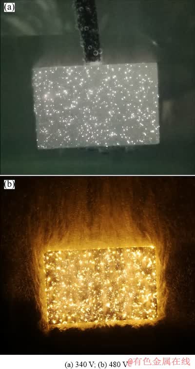
Fig. 11 Spark appearance on surface of specimens treated by PEO under different voltages
Frequency is defined as the number of pulses per second, namely the reciprocal of the time for one cycle, as shown in Eq. (8):
 (8)
(8)
where f is the frequency, Ton is the working time of the pulse voltage in one cycle (Ton+Toff), and is also referred to as the arcing time, and Toff is the time of the arc extinguishing. According to Eq. (8), with the frequency varying from 700 to 2000 Hz, the single pulse cycle shortens from 1.4 to 0.5 ms, implying that in the case of constant duty ratio, the arcing time in one cycle becomes short. Hence, fewer substances are deposited on the coatings, and the growth of the coating becomes slow. In addition, when the frequency increases, the number of pulses per second increases, which leads to the augmentation of the sites of the breakdown discharges, and as a result, it facilitates the growth of the coating. Under the interaction of above two aspects, the coating thickness along with its corrosion resistance in HNO3 medium decreases with the increase of frequency as shown in Fig. 3. Furthermore, under the high frequency condition, there is an increase in the quantity of micropores on the surface of coatings of Samples 1, 2, 5 and 6. However, the use of high frequency induces a decrease in the energy of the single pulse, which is advantageous for the miniaturization of pore size. Eventually, the coatings of Samples 1, 2, 5 and 6 exhibit a relatively dense structure and superior anti-corrosion property in NaCl medium.
The duty ratio (D) is the ratio of the arcing time to the total time in one cycle.
 (9)
(9)
When the frequency is fixed, a smaller duty ratio suggests shorter arcing time and longer arc extinguishing time in a single cycle. As a result, with the decrease of duty ratio, the coating becomes thin, as illustrated in Fig. 3. However, the generated energy and heat can be fully released, which is helpful to reduce the number of larger micropores as well as surface porosity. For instance, compared with the coating of Sample 6, the coating of Sample 5 prepared under the duty ratio of 20% possesses fewer large-sized micropores and lower surface porosity, which decrease from 3% to 1% and from 5.2% to 4.7%, respectively.
There exists a interaction between voltage and frequency. High voltage accelerates the reaction of PEO, and low frequency prolongs the time of one cycle. As a result, for a fixed duty ratio, when high voltage combines with low frequency, more molten material is generated, and the coating thickness as well as corrosion resistance of the coating in HNO3 medium increases significantly. However, their interaction also results in the release of a considerable amount of energy, which is demonstrated by the current value of Sample 8 shown in Fig. 1. This causes a significant increase both in the pore size and in the surface porosity of Samples 7 and 8, as presented in Figs. 7-9, so the corrosion resistances of Samples 7 and 8 in NaCl medium are worse.
There is also a interaction between frequency and duty ratio. High frequency can shorten the time of one cycle, in which the arcing time is reduced while arc extinguishing time is increased due to the small duty ratio. Finally, in one cycle, their interaction decides the arcing and extinguishing time, namely, it significantly shortens the arcing time and elongates the arc extinguishing time. This decreases the content of produced molten material and the coating thickness, and thus slightly reduces the corrosion resistance of the coating in HNO3 medium. Additionally, not only do the generated gas bubbles decrease, but the resultant energy and heat reduce, resulting in the decrease of larger micropores and enhancement of the anti-corrosion property of the coating in NaCl medium.
Research has shown that under the condition of high voltage, reducing the duty ratio increases the peak current [24]. So, the interaction between them causes the damage on the PEO equipment to some extent. Furthermore, it can be observed from Tables 2, 3 and Fig. 3 that the corrosion resistances of the coatings prepared under the duty ratios of 20% and 30% in HNO3 medium are not significantly different. Therefore, the optimum scheme of the three factors of electrical parameters for preparing the coating with the best anti-corrosion property in HNO3 medium should be adjusted to A2B2C2, i.e. high voltage, low frequency, and large duty ratio. Because their interaction not only ensures the safety of PEO equipment, but also increases the reaction rate and reaction time of PEO, which increases the coating thickness and content of the anti-corrosion phase, and further improves the corrosion resistance of the coating in HNO3 medium. In contrast, when low voltage and high frequency combine with a small duty ratio (A1B1C1), the PEO reaction rate decreases, but the arc extinguishing time increases. As a result, the obtained coating possesses the optimum anti- corrosion performance in NaCl medium due to the smallest pore size and densest microstructure (Figs. 7 and 9 for Sample 1 and Table 3).
5 Conclusions
(1) The experimental design of this study is the key to investigate the interactions among electrical parameters including voltage, frequency and duty ratio, and the results show that not only voltage, frequency, and duty ratio but also their interactions significantly affect the coating.
(2) The influences of individual factors of voltage, frequency, and duty ratio on the thickness and corrosion resistance of the coatings are different. Voltage exhibits the greatest impact, followed by frequency, and the influence of duty ratio is the least. By increasing the voltage, decreasing the frequency or increasing the duty ratio, the corrosion resistance of the coating in HNO3 medium is enhanced, while its corrosion resistance in NaCl medium is reduced.
(3) The interactions between two factors have a great influence on the thickness and corrosion resistance of the coating. For coating thickness, the influence of the interaction between voltage and frequency is greater than that of the independent factors of frequency and duty ratio. Regarding the corrosion resistance of the coating in HNO3 medium, the effects of the interaction between two factors of voltage and frequency are greater as compared with the individual factor of duty ratio. The interaction between voltage and frequency exhibits a more significant impact on the corrosion resistance of the coating in NaCl medium compared with duty ratio.
(4) The interaction among the three factors has a significant influence on the corrosion resistance of the coating. The combination of high voltage, low frequency and large duty ratio (A2B2C2) increases the reaction rate and reaction time of PEO. Hence, it increases the coating thickness, content of anti-corrosion phases and corrosion resistance of the coating in HNO3 medium. However, under low voltage and high frequency matching with a small duty ratio (A1B1C1), the obtained coating exhibits the best corrosion resistance in NaCl medium, since their interaction decreases the reaction rate of PEO and prolongs the arc extinguishing time in one cycle.
References
[1] WEN Lei, WANG Ya-ming, ZHOU Yu, OUYANG Jia-hu, GUO Li-xin, JIA De-chang. Corrosion evaluation of microarc oxidation coatings formed on 2024 aluminium alloy [J]. Corrosion Science, 2010, 52: 2687-2696.
[2] VENUGOPAL A, PANDA R, MANWATKAR S, SREEKUMAR K, RAMA KRISHNA L, SUNDAR- ARAJAN G. Effect of micro arc oxidation treatment on localized corrosion behaviour of AA7075 aluminum alloy in 3.5% NaCl solution [J]. Transactions of Nonferrous Metals Society of China, 2012, 22: 700-710.
[3] ZHAO J, XIA L, SEHGAL A, LU D, MCCREERY R L, FRANKEL G S. Effects of chromate and chromate conversion coatings on corrosion of aluminum alloy 2024-T3 [J]. Surface & Coatings Technology, 2001, 140: 51-57.
[4] OSKOUEI R H, IBRAHIM R N. The effect of a heat treatment on improving the fatigue properties of aluminium alloy 7075-T6 coated with TiN by PVD [J]. Procedia Engineering, 2011, 10: 1936-1942.
[5] XIE Huan-jun, CHENG Ying-liang, LI Shao-xian, CAO Jin-hui, CAO Li. Wear and corrosion resistant coatings on surface of cast A356 aluminum alloy by plasma electrolytic oxidation in moderately concentrated aluminate electrolytes [J]. Transactions of Nonferrous Metals Society of China, 2017, 27: 336-351.
[6] WANG Zhi-hu, ZHANG Ju-mei, LI Yan, BAI Li-jing, ZHANG Guo-jun. Enhanced corrosion resistance of micro-arc oxidation coated magnesium alloy by superhydrophobic Mg-Al layered double hydroxide coating [J]. Transactions of Nonferrous Metals Society of China, 2019, 29: 2066-2077.
[7] CHENG Ying-liang, MAO Mo-ke, CAO Jin-hui, PENG Zhao-mei. Plasma electrolytic oxidation of an Al-Cu-Li alloy in alkaline aluminate electrolytes: A competition between growth and dissolution for the initial ultra-thin films [J]. Electrochimica Acta, 2014, 138: 417-429.
[8] ZHANG Yi, WU Ye-kang, CHEN Dong, WANG Rui-qiang, LI Da-long, GUO Chang-hong, JIANG Gui-rong, SHEN De-jiu, YU Sheng-xue, NASH P. Micro-structures and growth mechanisms of plasma electrolytic oxidation coatings on aluminium at different current densities [J]. Surface and Coatings Technology, 2017, 321: 236-246.
[9] XIANG Nan, SONG Ren-guo, ZHAO Jian, LI Hai, WANG Chao, WANG Zhi-xiu. Microstructure and mechanical properties of ceramic coatings formed on 6063 aluminium alloy by micro-arc oxidation [J]. Transactions of Nonferrous Metals Society of China, 2015, 25: 3323-3328.
[10] GU Yan-hong, BANDOPADHYAY S, CHEN Cheng-fu, GUO Yuan-jun, NING Cheng-yun. Effect of oxidation time on the corrosion behavior of micro-arc oxidation produced AZ31 magnesium alloys in simulated body fluid [J]. Journal of Alloys and Compounds, 2012, 543: 109-117.
[11] TRAN Q P, KUO Y C, SUN J K, HE J L, CHIN T S. High quality oxide-layers on Al-alloy by micro-arc oxidation using hybrid voltages [J]. Surface & Coatings Technology, 2016, 303: 61-67.
[12] FATKULLIN A R, PARFENOV E V, YEROKHIN A, LAZAREV D M, MATTHEWS A. Effect of positive and negative pulse voltages on surface properties and equivalent circuit of the plasma electrolytic oxidation process [J]. Surface & Coatings Technology, 2015, 284: 427-437.
[13] LI Qing-biao, LIANG Jun, LIU Bai-xing, PENG Zhen-jun, WANG Qing. Effects of cathodic voltages on structure and wear resistance of plasma electrolytic oxidation coatings formed on aluminium alloy [J]. Applied Surface Science, 2014, 297: 176-181.
[14] KASEEM M, KAMIL M P, KO Y G. Electrochemical response of MoO2-Al2O3 oxide films via plasma electrolytic oxidation [J]. Surface & Coatings Technology, 2017, 322: 163-173.
[15] DEHNAVI V, LUAN Ben-li, SHOESMITH D W, LIU Xing-yang, ROHANI S. Effect of duty cycle and applied current frequency on plasma electrolytic oxidation (PEO) coating growth behavior [J]. Surface & Coatings Technology, 2013, 226: 100-107.
[16] ZHANG Xin-meng, TIAN Xiu-bo, GONG Chun-zhi, YANG Shi-qin. Dimensional structure and effect of duty cycle on microarc oxidation ceramic coatings fabricated on LY12 aluminum alloy [J]. Rare Metal Materials and Engineering, 2010, 39: 369-373. (in Chinese)
[17] EGORKIN V S, GNEDENKOV S V, SINEBRYUKHOV S L, VYALIY L E, GNEDENKOV A S, CHIZHIKOV R G. Increasing thickness and protective properties of PEO-coatings on aluminum alloy [J]. Surface & Coatings Technology, 2017, 334: 29-42.
[18] ARUNNELLAIAPPAN T, KISHORE BABU N, RAMA KRISHNA L, RAMESHBABU N. Influence of frequency and duty cycle on microstructure of plasma electrolytic oxidized AA7075 and the correlation to its corrosion behavior [J]. Surface & Coatings Technology, 2015, 280: 136-147.
[19] MA Ying, ZHAN Hua, MA Yue-zhou, Lü Wei-ling, FENG Jun-yan, GAO Wei. Effects of electrical parameters on microstructure and corrosion resistance of micro-arc oxidation coatings on AZ91D magnesium alloys [J]. The Chinese Journal of Nonferrous Metals, 2010, 20: 1467-1473. (in Chinese)
[20] MA Ying, FENG Jun-yan, MA Yue-zhou, ZHAN Hua, GAO Wei. Comparative study on characterization of corrosion resistance of micro-arc oxidation coatings on magnesium alloys [J]. Journal of Chinese Society for Corrosion & Protection, 2010, 30: 442-448. (in Chinese)
[21] MA Y, NIE X, NORTHWOOD D O, HU H. Systematic study of the electrolytic plasma oxidation process on a Mg alloy for corrosion protection [J]. Thin Solid Films, 2006, 494: 296-301.
[22] XUE Wen-bin, DENG Zhi-wei, LAI Yong-chun, CHEN Ru-yi. Analysis of phase distribution for ceramic coatings formed by microarc oxidation on aluminum alloy [J]. Journal of the American Ceramic Society, 1998, 81: 1365-1368.
[23] WEI Tong-bo, YAN Feng-yuan, TIAN Jun. Characterization and wear- and corrosion-resistance of microarc oxidation ceramic coatings on aluminum alloy [J]. Journal of Alloys and Compounds, 2005, 389: 169-176.
[24] CHEN Ming. Research on the local arc discharge mechanism and the characteristics of power supply in micro-arc oxidation of magnesium alloy [D]. Lanzhou: Lanzhou University of Technology, 2010: 55-56. (in Chinese).
安凌云,马 颖,剡晓旭,王 晟,王占营
兰州理工大学 省部共建有色金属先进加工与再利用国家重点实验室,兰州 730050
摘 要:在碱性硅酸盐体系中对纯铝进行等离子体电解氧化处理。采用正交实验研究电压、频率、占空比及其交互作用对等离子体电解氧化膜层厚度和耐蚀性能的影响。通过Image J软件测量膜层截面以获得膜层厚度,并分别采用点滴和电化学实验评价膜层在HNO3和NaCl介质中的耐蚀性能。结果表明,本研究实验设计是研究电参数间交互作用的关键所在。各电参数不仅独立地影响膜层,而且其交互作用也显著影响膜层。高电压、低频率和大占空比间的交互作用使膜层厚度和耐蚀物相含量显著增加,进而改善膜层在HNO3腐蚀介质中的耐蚀性能;反之,低电压、高频率和小占空比间的交互作用使膜层最为致密,膜层在NaCl腐蚀介质中的耐蚀性最佳。
关键词:铝;等离子体电解氧化;电压;频率;占空比;交互作用;正交实验;耐蚀性能
(Edited by Wei-ping CHEN)
Foundation item: Project (1111RJDA011) supported by the Creative Research Group Fund of Gansu Province, China; Project (SKLAB02015006) supported by the State Key Laboratory Open Fund of Advanced Processing and Recycling of Nonferrous Metals, China
Corresponding author: Ying MA; Tel: +86-931-2976688; E-mail: mayingjournal@yeah.net
DOI: 10.1016/S1003-6326(20)65262-1

