Article ID: 1003-6326(2005)05-1130-08
Observation and theoretic analysis of gas-bubble formation and growth in water-model
WU Rui-zhi(������), SHU Da(�� ��), SUN Bao-de(�ﱦ��),
WANG Jun(�� ��), LU Yan-ling(½����)
(State Key Laboratory of Metal Matrix Composites, Shanghai Jiaotong University, Shanghai 200030, China)
Abstract: The behavior of bubbles is observed with high-speed digital camera in water-model. It is found that each bubble has three processes: bubble formation, bubble coalescence and bubble division. Bubble shape is spherical firstly, then elliptical and spherical crown after coalescence, and spherical again after division. These phenomena are explained theoretically. And the bubble size is defined newly. The so-defined bubble size is measured through digital camera and LECO graphical analyzer. And the measured results are compared with those in literatures.
Key words: bubble formation; bubble coalescence; bubble division; high-speed digital camera; bubble size; water-model CLC number: TF114; TG292
Document code: A
1 INTRODUCTION
The refinement of molten metal is an indispensable part in aluminum/aluminum alloy foundry and metallurgic industry. In refining process, gas is often puffed into molten metal to act for de-oxygen, de-hydrogen and so on. The refining effects are determined by the distribution and dimension of gas bubbles. Accordingly, it is very important to research the refining process to understand the bubble formation and growth. But it is very difficult to know the behavior of gas-bubble in high temperature metal melt. It has been known that, the viscosity of liquid is the main factor influencing the hydrodynamic behavior of gas bubbles[1]. Water at 20�� has a viscosity close to that of aluminum melt at 750��, so that the hydrodynamic behavior of bubbles is similar in both cases. Therefore, the process of gas-bubble formation and growth is always studied in water-model[1-4]. A great deal of efforts has been made to investigate the behavior of bubble in liquid. However, it is not understood profoundly by refining researchers yet[5, 6].
Through the observation with digital camera, some have found that every two bubbles formed in liquid coalesce as a big bubble. However, some found that every three bubbles formed in liquid coalesce as a big bubble[7, 8]. With high-speed digital camera, the coalescence process is also observed in this paper.
Reynolds number is always used to estimate the shape of bubbles. Sigworth et al[9] and Engh et al[10] pointed out that, bubbles in aluminum would remain spherical with Reynolds number of about 2000. When the Reynolds number is larger than 2000, the bubbles would become ellipsoids or wobbling ellipsoids. At very high Reynolds number, the bubbles would form spherical crowns. In this paper, all of the three shapes are observed under the same experiment condition.
In the aspect of bubble size, many researchers have obtained many kinds of empirical equations through a great deal of experimental data. The theoretical deviation about the bubble size exists also in many forms[11-13]. In most of the theoretical deviations, the bubble size is defined as the size when the bubble separates from the gas inlet (named as escape volume). Due to the coalescence of bubbles, this definition is seen unreasonable by some researchers recently. In their opinion, the bubble size should represent the size of big bubble, which is coalesced with two (or three) bubbles. However, because of the bubble division after the bubble coalescence, the bubbles before the division are all unstable. Only the bubbles after the bubble division are stable. Accordingly, the bubble size should be defined as the size of the bubbles after division. In this paper, the bubble size after the bubble division is measured and compared with that in literatures.
2 EXPERIMENTAL
Polyethylene tank is filled with water. The gas is puffed into water through a standstill graphite rotary impeller head. There are four gas-pores in the end of the impeller head. The diameter of gas-pores is 3mm. The gas that is puffed into water in the experiment is 99.99% pure nitrogen. When gas is puffed into water, a high-speed digital camera is used to trace the bubble behavior. The schematic diagram of the experiment is shown in Fig.1.
In the experiment, the gas-flow rate is 0.157L/s. The depth of the inlet gas-pore in water is 300mm. The ambient light comes from a 1300��2 AC lamp. The operation parameters of high-speed camera are listed in Table 1.
3 OBSERVED RESULTS
3.1 Before bubble formation
During the time that the gas has started being puffed into water but gas-bubbles have not formed, the observed results can be seen in Fig.2. It is known that the gas is in the iterative state, in which the gas tries to push water outwards to form bubble but fails.
3.2 Process of first bubble formation
The observed result can be seen in Fig.3. The gas pushes the water and forms the first bubble in the shape of spherical. And the bubble grows up with the time going on.
Under the pressure between the inclined plane of the graphite tube and water, the bubble is squeezed as flat shape on the inclined plane of graphite tube (at t=469/2000s). And the flat bubble grows in the lateral direction. When the flat bubble grows to the edge of the inclined plane, the bubble shape becomes spherical again because the barrier of the inclined plane in vertical direction disappears there (at t=494/2000s and 549/2000s). When the time is 591/2000s, an entire bubble forms and it separates the inclined plane and fillister entirely and rises vertically.
3.3 Second bubble
This process can be seen in Fig.4. After the first bubble separates the inclined plane and fillister, the first bubble shape changes from spheroid to spherical crown (at t=657/2000s). In the meantime, the second bubble grows up. And the second bubble is ��absorbed�� by the first one when it grows to a definite size. The two bubbles coalesce as one bubble in the shape of mushroom (at t=710/2000s). Then the coalescent bubble shape changes gradually from mushroom shape to spherical crown shape again (at t=746/2000s).
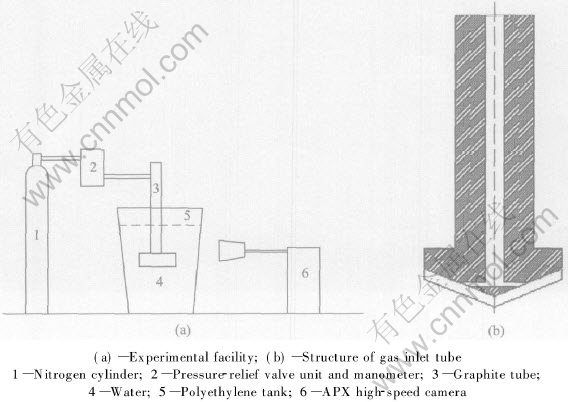
Fig.1 Schematic diagram of experimental set-up
Table 1 Operation parameters of high-speed camera


Fig.2 State of gas before it forms bubble(width of fillister is 6mm)

Fig.3 Formation process of first bubble

Fig.4 Formation process of second bubble

Fig.5 Behavior of third bubble
3.4 Third bubble
This process can be seen in Fig.5. When this coalescent bubble rises, the coalescent bubble breaks up into bubble group (at t=773/2000s). At the same time, the third bubble forms. The third bubble is in spherical shape initially (at t=979/2000s). Then it becomes in cone shape (at t=1073/2000s). This bubble continues to rise. At the time of 1133/2000s, it catches up with the bubble group. And it breaks up into bubble group again.
3.5 Fourth and following bubbles
This process can be seen in Fig.6. The fourth bubble is spherical shape initially. Then it becomes spherical crown shape. During this time, the fifth bubble forms and rises up. When it rises near the fourth bubble, it becomes cone shape because of the ��absorption�� of the fourth bubble (at t=1394/2000s). Then the fifth bubble coalesces with the fourth bubble (at t=1434/2000s). The coalescent bubble continues to rise and then breaks up into bubble group (at t=1494/2000s).
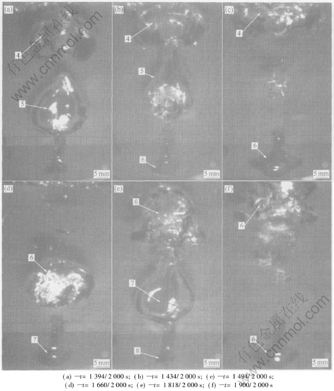
Fig.6 Behavior of fourth and following bubbles
At the time of 1660/2000s and 1818/2000s, the sixth and the seventh bubbles form respectively. The formation, coalescence and division of the two bubbles is the same as those of the fourth and fifth bubbles. What��s more, the following bubbles repeat this process circularly.
4 THEORETICAL ANALYSIS OF OBSERVED RESULTS
4.1 Before formation of bubble
At the start of puffing gas, the gas-pressure and gas-flow rate both fail to reach stable state and their values are both small. The gas-pressure and gas-flow rate increase gradually. At this time, the geometrical relationship of the gas/liquid interface is shown in Fig.7. It is known that there are three forces applied to the gas/liquid interface. The three forces are gas pressure, interfacial tension and the static pressure of the liquid respectively. The direction of the gas pressure and interfacial tension opposes to that of the static pressure. Because the gas pressure is very small initially, the gas pressure and interfacial tension cannot resist the static pressure. The gas pressure and the interfacial tension are not great enough to push the gas/liquid interface outwards (at t=0 s in Fig.2). The gas pressure increases with the time. When the gas pressure and the interfacial tension are greater than the static pressure of liquid, the gas/liquid interface will be pushed outwards.

Fig.7 Geometrical relationship of gas/liquid interface
The value of interfacial tension is 2��/R (where R is the curvature radius of interface). From Fig.7, it is known that the interfacial tension can also be shown as -2��cos��/r (where r is the radius of gas pore). If the interface is pushed outwards, �� will decrease. And the interfacial tension decreases with the interface being pushed outwards. The gas pressure and interfacial tension are less than the static pressure of liquid again. And the interface is pushed back again (at t=3/2000s in Fig.2).
In this way, the gas pressure increases. The interfacial tension decreases when the interface is pushed outwards and increases when the interface is pushed back. Therefore under the forces of gas pressure, interfacial tension and the static pressure of liquid, the interface goes outwards and backwards repeatedly at the first stage (as seen in Fig.2).
4.2 Formation of second bubble and its coalescence with previous one
When the first bubble rises upwards in water, the liquid in front of the bubble is pushed away and a negative pressure zone forms behind the bubble. The liquid pushed away by the bubble moves towards the negative pressure zone. Under the effects of the liquid movement, the bubble shape changes from the spheroid to the spherical crown (at t=657/2000s in Fig.4). The schematic diagram of the bubble and the liquid movements is shown in Fig.8.

Fig.8 Schematic diagram of bubble and liquid movements
After the second bubble forms, it is absorbed upwards by the negative pressure zone and coalesces with the first bubble. The shape of the second bubble is changed as an upright ellipsoid. Therefore the coalescent bubble is in mushroom shape (at t=710/2000s in Fig.4). And a new negative pressure zone forms under this bubble. Under the effects of the two negative pressure zones, the movement state of liquid is shown in Fig.9.

Fig.9 Movement of liquid under effects of two negative pressure zones
From Fig.9, under the effects of the movement of liquid, the length of the upright ellipsoid will become shorter and shorter. Then the coalescent bubble becomes a ��big�� spherical crown (at t=746/2000s in Fig.4).
4.3 Formation of third bubble and its coalescence with previous bubble group
On the coalescent ��big�� spherical crown shape bubble, the curvature radius at the bottom surface of the spherical crown is much greater than that at the upper surface of the spherical crown. Therefore the interfacial tension on the bottom surface of the spherical crown is much less than that on the upper part[14-16]. To reach equilibrium, the bottom surface moves towards the inner of bubble to gain a relatively small curvature radius. A coalescent bubble becomes several small petal-like bubbles. Accordingly the coalescent bubble is divided as many small bubbles. The bubble group is gained in this way (at t=773/2000s, 951/2000s and 979/2000s in Fig.5).
After the third bubble forms, it rises up in the spherical shape. Because the previous bubbles move slowly, the third bubble catches up with the bubble group. Under the negative pressure zone of the bubble group, the third bubble shape is changed as cone (at t=1073/2000s in Fig.5). Then the third bubble coalesces with the bubble group and breaks up into bubble group.
4.4 After formation of third bubble
When the fourth bubble forms, it is far away from the previous bubbles. It cannot catch up with them. Therefore it rises up freely. When the fifth bubble forms, it catches up with the fourth bubble and coalesces with it because of the negative pressure zone formed by the fourth bubble. And the following bubbles will repeat the behavior of the fourth and the fifth bubbles continuously. That is to say, every two bubbles coalesce as one bubble.
4.5 Shape of bubbles
From the observed results, it is known that each bubble is spherical at first, then elliptical. After the coalescence happens, the big bubble will be spherical crown. Finally, when the big bubble divides as bubble group, the bubble will be spherical again. This phenomenon can be explained clearly by the above mentioned ��negative zone�� and the movement of flow because of the existence of ��negative zone��.
This can also be explained with the variation of Reynolds number. At first, the bubble speed is very small. The Re number is small accordingly. Therefore the bubble shape is spherical. With accelerated the upward movement of bubble, the speed of bubble increases. And the Re number increases also. When the Re number reaches a definite value, the bubble shape will be elliptical. After the coalescence happens, because both the bubble size and bubble speed increase, the Re number is very large. And the bubble shape becomes spherical crown. After the bubble division, the bubble size becomes very small. The Re number decreases accordingly. And the bubble shape becomes spherical also.
4.6 Bubble size after division
From Figs.3-6, it can be observed that the bubble diameter when the bubble escapes from gas inlet is about 25-30mm (the diameter of gas inlet is 3mm). To get the bubble size after the bubbles divide as little bubbles, the bubbles are shot with digital camera. The digital picture of bubbles is analyzed with LECO graphical analyzer software. The analyzed results are shown in Fig.10. The average diameter of the bubble after division is 12.5mm. The bubble diameter reported in literatures under the same condition is about 25mm and 35mm respectively[7]. From the comparison, it is known that the bubble size in literatures is larger than the size measured in this paper. Because the bubble size in literatures is the size before the bubble division. However the bubble size in this paper is the size after the bubble division.

Fig.10 Bubbles picture(a) and analyzed results(b)
5 CONCLUSIONS
1) During the period when the gas-flow is not steady, the gas/liquid interface is in the iterative state that gas tries to push water to form bubble but fails. Until the gas-flow is steady, the interface is pushed outwards and bubble forms.
2) The behavior of bubble in liquid includes three processes: formation, coalescence and division.
3) The shape of gas bubble varies at different stages: spherical in formation stage, then elliptical. After the coalescence happens, the big bubble will be spherical crown. Finally, when the big bubble divides as bubble group, the bubble will be spherical again.
4) The bubble size is defined as the size of the bubbles after division. The bubble size is smaller than that in literatures.
REFERENCES
[1]Brun P L. Hydrogen removal efficiency of in-line degassing units [A]. Proc of Sessions, TMS Annual Metting, Light Metals [C]. 2002. 869-875.
[2]Johansen S T, Gradahl S, Dahle O, et al. Experimental determination of bubble sizes in melt refining reactors [A]. Proc of Session, TMS Annual Metting, Light Metals [C]. 1996. 1027-1031.
[3]Carpenter K A, Hanagan M J. Efficiency modeling of rotary degasser head configurations and gas introduction methods, Part (��)��water tank tests [A]. Light Metals [C]. 2001. 1017-1020.
[4]Chen J J J, Zhao J C, Lacey P V, et al. Flow pattern detection in a melt treatment water model based on shaft power measurements [A]. Proc of Session, TMS Annual Metting, Light Metals [C]. 2001. 1021-1025.
[5]Erkesskin K T, Fredrichs H A, Dahl W, et al. Simulation of gas dispersion in a metallurgical bubble reactor [J]. Steel Research, 1993, 64: 581-587.
[6]Lin Z H, Guthrie R I L. Modeling of metallurgical emulsions [J]. Metallurgical and Materials Transactions B, 1994, 25: 855-864.
[7]Che D F, Lin Z H, Chen X J, et al. Experimental investigation on bubble formation in a liquid [J]. Journal of Iron and Steel Research, 1994, 6: 9-14.(in Chinese)
[8]Yin B, Zhang M C, Tan C J, et al. Visualized research on movement characteristics of bubbles in an internally circulating fluidized bed [J]. Power Engineering, 2003, 23: 2143-2146.(in Chinese)
[9]Sigworth G K, Engh T A. Chemical and kinetic factors related to hydrogen removal from aluminum [J]. Metallurgical Transactions B, 1982, 13B: 447-460.
[10]Clift R, Grace J C, Weber M E. Bubbles, Drops, and Particles [M]. New York: Academic Press, 1978.
[11]Iron G A, Guthrie R I L. Bubble formation at nozzles in pig iron [J]. Metallurgical Transactions B, 1978, 9B:101-110.
[12]Mao Z, Zheng C, Feng Y. Study in bubble behavior in a three-phase fluidized bed by means of photographic method [J]. Journal of Beijing Institute of Chemical Technology, 1994, 21: 1-4.(in Chinese)
[13]Xiao X G, Xie Y G. The Basis of Metallurgical Reaction Engineering [M]. Beijing: Metallurgical Industry Press, 1997. 121.
[14]Bertherat M, Odievre T, Allibert M, et al. A radioscopic technique to observe bubbles in liquid aluminum [A]. Proc of Sessions, TMS Annual Meeting, Light Metals [C]. 2002. 861-867.
[15]Laux H, Johansen S T. Computer simulation of bubble formation in a gas-fluidized bed [A]. FLUIDIZATION IX 9th Engineering Foundation Conference on Fluidization [C]. Durango Colorado, 1998. 517-524.
[16]Johansen S T, Gradahl S, Johnsen I. R. Experimental determination of bubble sizes in melt refining reactors [A]. Proc of Sessions, TMS Annual Meeting, Light Metals [C]. 1996. 1027-1031.
Foundation item: Project(G1999064900-4) supported by the National Basic Research Program of China
Received date: 2005-02-24; Accepted date:2005-06-02
Correspondence: SUN Bao-de, Professor, PhD; Tel: +86-21-62932914; Fax: +86-21-62932914; E-mail: bdsun@sjtu.edu.cn
(Edited by YANG Bing)

