


Trans. Nonferrous Met. Soc. China 22(2012) 2092-2097
Effect of pattern coating thickness on characteristics of
lost foam Al-Si-Cu alloy casting
Majid KARIMIAN1, 2, Ali OURDJINI2, Mohd HASBULLAH IDRIS2, Hassan JAFARI2, 3
1. Mechanical Engineering Department, Islamic Azad University of Komeyni Shahr, Esfahan 119-84175, Iran;
2. Materials Engineering Department, Faculty of Mechanical Engineering,
Universiti Teknologi Malaysia, 81310 UTM Skudai, Johor, Malaysia;
3. Materials Engineering Department, Faculty of Mechanical Engineering,
Shahid Rajaee Teacher Training University, Tehran 16785-136, Iran
Received 17 November 2011; accepted 18 April 2012
Abstract: An experimental study on lost foam casting of an Al-Si-Cu alloy was conducted. The main objective was to study the effect of pattern coating thickness on casting imperfection and porosity percentage as well as eutectic silicon spacing of the alloy. The results showed that increasing slurry viscosity and flask dipping time influenced the casting integrity and microstructural characteristics. It was found that thinner pattern coating produced improved mould filling, refined microstructure and higher quality castings containing less porosity.
Key words: aluminum alloy; lost foam casting; coating thickness; slurry viscosity; dipping time; porosity
1 Introduction
Lost foam casting (LFC) as a cost-effective and environmentally friendly casting process is widely used for aluminum alloy castings to produce complex engineering components [1,2]. The layer of coating applied on the pattern foam is a crucial parameter for producing high quality castings [3]. It was proposed that in lost foam casting process, refractory coating is developed on the pattern surface to provide support against the weight of the sand before the liquid metal solidifies as well as withstands the high temperature of molten metal [4]. Recently, it was reported [5] that the coating also provides an insulation barrier to keep the molten metal from losing too much heat, which may result in premature solidification. Thus, the coating may facilitate elimination of the degraded foam products including liquid and gases. In addition, LIU et al [4] reported that the coating layer decreases the heat transfer coefficient between the liquid metal and sand, resulting in the improvement of metal fluidity. Although, several studies have investigated the influence of coating in LFC [6-8], better understanding of the effect of coating on casting quality in LFC process is essential. Moreover, the effect of foam coating layer can be more complex due to the effect and interactions of several process factors. In the literature, some research work was conducted in order to improve the pattern coating properties. Zircon flour, kaolin and talc as suitable refractory compositions were proposed for coating preparation in LFC of Al®C7% Si [9], while a mixture of zircon flour together with aluminum silicate and bentonite was also suggested as a slurry composition for the same cast alloy [10].
The composition and thickness of pattern coating are two critical factors governing the LFC. Limited studies have been carried out on the effect of coating thickness on other process parameters in LFC, but due to lack of knowledge on this area, it is therefore necessary to investigate how coating thickness would affect the casting characteristics. The present paper is aimed to investigate the effect of coating thickness through different slurry viscosities and dipping times on casting imperfection, porosity percentage and eutectic silicon spacing (ESS) of an Al-Si-Cu cast alloy.
2 Experimental
A five-step pattern with the dimensions shown in Fig. 1 was designed and prepared for the LFC experiment using a hot wire cutter with an accuracy of °ņ0.5 mm from a foam (polystyrene) block with 20 kg/m3 in density. The thickness of the steps was designed as 3, 6, 12, 18 and 24 mm. For the purpose of improving liquid metal feeding during pouring, extra 10 mm-long polystyrene foam was added to the top-thickest section of the pattern. In addition, a pouring cup was cut from the same foam material and attached to the top of the pattern.
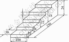
Fig. 1 Stepped pattern designed for experiments (Unit: mm)
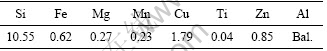
In order to deposit a suitable coating on the pattern, a mixture of zircon flour and colloidal silica having different viscosities of 42, 35, 27 or 20 s, measured by Zahn cup No. 5, was prepared. Coating was achieved by dipping the patterns into the slurry for three durations of 20, 40 and 60 s followed by drying at room temperature for up to 24 h. A scanning electron microscope (SEM) was used for measuring the coating thickness. An cast Al-Si-Cu alloy with the chemical composition given in Table 1 was melted in a 60 kg-induction furnace and the molten metal was poured at 740 °ś. The temperature was controlled within °ņ5 °ś variation. All castings were removed from the moulds upon cooling to room temperature.
Table 1 Chemical composition of Al-Si-Cu alloy used (mass fraction, %)
For the purpose of the casting integrity/geometry analysis, the sections with 3 and 24 mm in thickness of the castings were evaluated for incomplete filling, surface imperfection as well as deficient edges and corners (misrun). Gas porosity and shrinkage defects within the 12 mm section of the castings were measured by an optical microscope equipped with an image analyzer and SEM. In addition, the average eutectic silicon spacing (ESS) of the microstructures was also measured by linear intercept method according to ASTM E112 standard within the same section of the castings.
3 Results and discussion
3.1 Coating characteristics and casting integrity
Coating on foam pattern is a significant parameter in producing high quality casting by LFC process as it maintains the shape of the mould cavity in the gap between the receding degradation of the pattern and advancing liquid metal filling the mould. In fact, the mould filling time is controlled by how fast the gases are generated and escaped through the mould sand. To allow rapid elimination of the gases both coating and mould sand should be permeable enough. Figure 2 shows the variation of coating thickness as a function of slurry viscosity for different dipping time. It is evident that with increasing the slurry viscosity from 20 to 35 s there was no significant change in the coating thickness, but as the viscosity increased to 42 s, the coating thickness increased significantly to a value of 0.26 mm for the 60 s dipping time. Moreover, increasing dipping time raised the coating thickness on the foam pattern due to more availability of the slurry to precipitate on the foam surface.
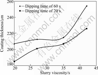
Fig. 2 Effect of slurry viscosity and dipping time on coating thickness
Figure 3 shows the cross sections of the coating layers produced with viscosities of 20 and 42 s after dipping for 60 s. It can be seen that the coating thickness is proportional to the slurry viscosity, as higher viscosity slurry produces thicker coating. Due to the reduced permeability in the thicker coatings, gas escaping through the coating and mould sand is slower, which retards the downward flow of the metal and causes misrun and entrapped gases. Figure 4 demonstrates the effect of coating thickness on the produced castings. As can be seen, increasing the coating thickness affected the quality of the casting and brought about misrun, which is in agreement with the results of GRIFFITHS and DAVIES [8]. From Fig. 4 it is also observed that by using slurry viscosities of 35 and 42 s with 60 s of dipping time, partial filling, particularly in the 3 mm section, was produced. In contrast, the casting produced with lower slurry viscosities, especially 20 s (Fig. 4(a)) for a fixed dipping time (60 s) showed complete filling and fewer surface imperfections can be observed.
Figure 5 shows the presence of pores in the coatings obtained using different slurry viscosities. It is clearly seen that thicker coatings (Figs. 5(a) and (b)) contain fewer pores compared with the thinner coatings (Figs. 5(c) and (d)). More pores in the coating mean higher permeability and rapid elimination of gases produced during foam®Cliquid metal interaction, which correlates well with heat transfer of a porous coating [11]. This indicates that a thicker coating provides lower heat transfer from molten metal to the mould and environment. Rapid gas elimination through the coating and mould sand increases liquid metal fluidity since there is little gas gap preventing the advancing flow front. The pore distribution shown in Fig. 5 has been taken from cross section of the coating and it is unlikely that it would affect surface roughness of castings.
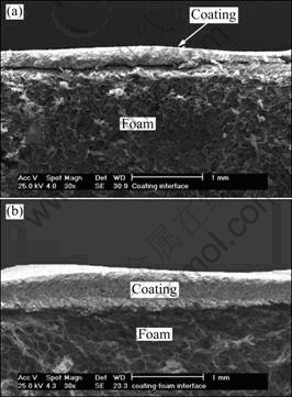
Fig. 3 SEM images of cross sections showing effect of slurry viscosity on coating thickness (Dipping time is fixed at 60 s): (a) 20 s; (b) 42 s
Pore distribution in coating surface with different dipping time is shown in Fig. 6. It can be seen that with a shorter dipping time, the pores in the coatings appear to be distributed uniformly compared with those observed in coating prepared with a longer dipping time. This may result in better casting quality in terms of casting integrity shown in Fig. 7, as a result of developed gas transferring compared to those obtained with a longer dipping time. The result is in good agreement with the previous studies by CHEN and PENUMADU [11], and KHODAI and PARVIN [12] that uniform and homogenous distribution of pores has a good correlation with transport properties of the porous coating.
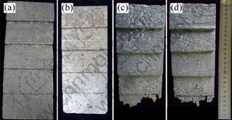
Fig. 4 Photos of castings produced with pattern coatings prepared under 60 s of dipping time and different slurry viscositie: (a) 20; (b) 27 s; (c) 35 s; (d) 42 s
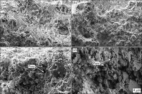
Fig. 5 SEM images showing pore distribution in coatings obtained with different slurry viscosities (Dipping time is fixed at 60 s): (a) 42 s; (b) 35 s; (c) 27 s; (d) 20 s
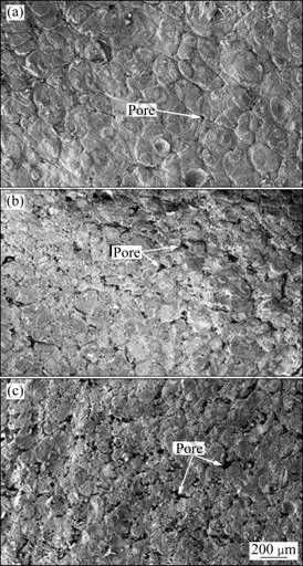
Fig. 6 SEM images showing pores distribution in coating surface with different dipping times: (a) 60 s; (b) 40 s; (c) 20 s
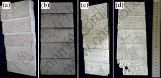
Fig. 7 Photos of castings produced with pattern coatings prepared under 20 s of dipping time and different slurry viscosities: (a) 20 s; (b) 27 s; (c) 35 s; (d) 42 s
Comparison of castings shown in Fig. 4 with those
in Fig. 7 confirms that by using a shorter dipping time, complete mould filling is obtained, especially in those castings produced with slurry viscosities of 35 and 42 s. This can be attributed to a decrease in coating thickness on the foam patterns causing an increase in flow rate of liquid metal to allow better filling of the thinner sections and ultimately producing quality casting. Indeed, as shown in Fig. 7, the best premium shape replication of casting was obtained with the dipping time of 20 s. Furthermore, Fig. 4 and Fig. 7 also reveal that slurry viscosity appears to have a more pronounced effect on casting integrity compared with dipping time as a lower slurry viscosity completely replicates the shape of the pattern regardless of dipping time.
3.2 Porosity
Figure 8 illustrates the porosity area fraction in the castings as function of slurry viscosity and dipping time used for developing coatings on the foam pattern. It can be seen that by increasing slurry viscosity and dipping time, the area fraction of porosity increases. As both parameters increase, the thickness and the permeability of coating reduce, which retard the penetration of the pyrolysis products (gas + liquid) through the coating [13-15]. When this happens, reaction time increases and leads to increased entrapped porosity in the castings.
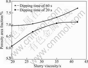
Fig. 8 Effect of slurry viscosity and dipping time on porosity area fraction in lost foam castings
According to previous studies [16,17], the use of low permeability coating reduces both size and number of lost foam casting defects. This is due to decreasing of liquid metal velocity, which accompanies an increase in mould filling time, increasing the time for foam products to escape through the coating. However, the results obtained in the present work (Fig. 4 and Fig. 7) are in disagreement with some of the reported results. This is probably because there are several process parameters controlling the formation of casting defects and not a single parameter on its own, as reported by HILL et al [18]. When examining the effect of coating thickness on the porosity area fraction, one should also take into account the foam pattern density and thickness, melt pouring temperature, stability of metal and other parameters in combination.
3.3 Eutectic silicon spacing
Figure 9 shows the optical microstructures of the lost foam castings produced using 42/60 and 20/20 s of slurry viscosity/dipping time, respectively. The microstructures contain the primary ¶Ń(Al) and Al-Si eutectic. It is seen that the eutectic silicon spacing (ESS) in the microstructures increased by using a higher slurry viscosity.
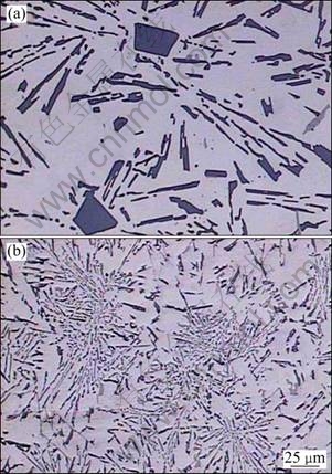
Fig. 9 Optical microstructures showing effect of slurry viscosity, dipping time on eutectic silicon spacing: (a) Viscosity of 42 s, dipping time of 60 s; (b) Viscosity of 20 s, dipping time of 20 s
Figure 10 reveals the increasing trend in ESS with increasing slurry viscosity in the castings. In general, larger ESS is obtained when coating thickness increases. This might be attributed to heat transfer characteristics which were significantly affected by coating thickness. Therefore, it can be inferred that thicker coating brings about coarser microstructure and as a result larger ESS is obtained. The present findings seem to be consistent with those reported by previous researchers [14, 19]. It should also be noted that slurry viscosity revealed more pronounced effect on the microstructure compared with that of dipping time as illustrated in Fig. 11.
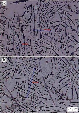
Fig. 10 Optical microstructures showing effect of dipping time on eutectic silicon spacing: (a) 20 s; (b) 40 s
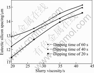
Fig. 11 Effect of slurry viscosity and dipping time on average eutectic silicon spacing
4 Conclusions
From the experimental studies, it can be concluded that increasing slurry viscosity or dipping time which increased coating thickness on foam pattern, resulted in significant influence on the casting integrity and microstructure. Thinner coating produced more pores, which facilitated gas escape during casting and resulted in better mould filling, less gas porosity within the casting and finer eutectic silicon spacing.
Acknowledgements
The authors acknowledge Universiti Teknologi Malaysia (UTM) for providing research facilities and Ministry of Science and Technology of Malaysia for funding the research project under E-science Fund Vote No. 79352.
References
[1] Guler K A, Kisasoz A, Karaaslan A. A novel method for Al/SiC composite fabrication: Lost foam casting [J]. International Journal of Materials Research, 2011, 3: 304-308.
[2] LIU Zi-li, PAN Qing-lin, CHEN Zhao-feng, LIU Xi-qin, TAO Jie. Heat transfer characteristics of lost foam casting process of magnesium alloy [J]. Transactions of Nonferrous Metals Society China, 2006, 16: 445-451.
[3] Caulk D A. A foam melting model for lost foam casting of aluminum [J]. International Journal of Heat and Mass Transfer, 2006, 49: 2124-2136.
[4] Liu X J, Bhavnani S H, Overfelt R A. Simulation of EPS foam decomposition in the lost foam casting process [J]. Journal of Materials Processing Technology, 2007, 182: 333-342.
[5] Akbarzadeh y, Rezaei m, Babaluo b, Charchi c, Azimi h, Bahluli Y. Microstructure, permeability and rheological behavior of lost foam refractory coatings [J]. Surface and Coatings Technology, 2002, 202: 4636-4643.
[6] Bakhtiyarov S L, Overfelt R A. Rheology of refractory coating materials used in lost foam casting process [J]. Journal of Elastomers & Plastics, 2008, 32: 73-85.
[7] Kumar S, Kumar P, Shan H S. Effect of filler material in zircon flour coating used in evaporative pattern casting process [J]. Indian Foundry Journal, 2004, 50: 34-40.
[8] Griffiths W D, Davies P J. The permeability of lost foam pattern coatings for Al alloy castings [J]. Journal of Materials Science, 2009, 43: 5441-5447
[9] Acimovic Z, Pavolic L, Trumbulovic l, Andric L J, stamatovic m. Synthesis and characterization of the cordierite ceramics from nonstandard raw materials for application in foundry [J]. Materials Letters, 2003, 57: 2651-2656.
[10] Kumar s, Kumar P, Shan H S. Characterization of the refractory coating material used in vacuum assisted evaporative pattern casting process [J]. Journal of Materials Processing Technology, 2009, 209: 2699-2706.
[11] CHEN X, PENUMADU D. Characterizing microstructure of refractory porous materials [J]. Journal of Materials Science, 2006, 41: 3403-3415.
[12] Khodai M, Parvin N. Pressure measurement and some observation in lost foam casting [J]. Journal of Materials Processing Technology, 2006, 206: 1-6.
[13] Shin S R, Lee Z H, Cho G S, Lee K W. Hydrogen gas pick-up mechanism of Al-alloy melt during lost foam casting [J]. Journal of Materials Science, 2004, 39: 1563-1569.
[14] Trumbulovic l, Acimovic z, Gulicija z, Andric l. Correlation of technological parameters and quality of castings obtained by the EPC method [J]. Materials Letters, 2004, 58: 1726-1731.
[15] Warner H, Miller B A, Littleton H E. Pattern pyrolysis defect reduction in lost foam castings [J]. Transactions of the American Foundrymen°Įs Society, 1998, 106: 777-785.
[16] Bennett s, Moody t, Vrieze a, Jackson m, Askeland D R, Ramsay C W. Pyrolysis defects in aluminum lost foam casting [J]. Transactions of the American Foundrymen°Įs Society, 1999, 107: 795-803.
[17] Zhao q, Burke j, Gustafson t. Foam removal mechanism in aluminum lost foam casting [J]. Transactions of the American Foundrymen°Įs Society, 2002, 110: 1399-1414.
[18] Hill m, Vrieze A E, Moody T L, Ramsay C W, Askeland D R. Effect of metal velosity on defect formation in Al LFCs[J]. Transactions of the American Foundrymen°Įs Society, 1998, 106: 365-374.
[19] Sands m, Shivkumar s. Influence of coating thickness and sand fineness on mold filling in the lost foam casting process [J]. Journal of Material Science, 2003, 38: 667-673.
ÕŅ≤„ļŮ∂»∂‘ŌŻ ßń£÷żAl-Si-CuļŌĹū÷żľĢĶń”įŌž
Majid KARIMIAN1, 2, Ali OURDJINI2, Mohd HASBULLAH IDRIS2, Hassan JAFARI2, 3
1. Department of Mechanical Engineering, Islamic Azad University of Komeyni Shahr, Esfahan 119-84175, Iran;
2. Department of Materials Engineering, Faculty of Mechanical Engineering,
Universiti Teknologi Malaysia, 81310 UTM Skudai, Johor, Malaysia;
3. Department of Materials Engineering, Faculty of Mechanical Engineering,
Shahid Rajaee Teacher Training University, Tehran 16785-136, Iran
’™ “™£ļ∂‘Al-Si-CuļŌĹūĹÝ––ŌŻ ßń£÷ż‘ž£¨—–ĺŅÕŅ≤„ļŮ∂»∂‘Al-Si-CuļŌĹū÷żľĢ»ĪŌ›°ĘŅ◊Ō∂¬ ļÕĻ≤ĺßĻŤľšĺŗĶń”įŌž°£ĹŠĻŻĪŪ√ų£¨ŐŠłŖÕŅ≤„ŨŃŌū§∂»ļÕ—”≥§ĹĢ◊’ Īľš∂‘÷żľĢĶńÕÍ’Ż–‘ļÕŌ‘őĘ◊ť÷Į”–”įŌž°£Ī°ĶńÕŅ≤„”–ņŻ”ŕń£«Ľ≥šŐÓ–‘ń‹Ķńłń…∆°ĘŌ‘őĘ◊ť÷ĮĶńŌłĽĮļÕĶÕŅ◊Ō∂∂»łŖ÷ ŃŅ÷żľĢĶńĽŮĶ√°£
ĻōľŁī £ļ¬ŃļŌĹū£ĽŌŻ ßń£÷ż‘ž£ĽÕŅ≤„ļŮ∂»£ĽĹ¨ŃŌū§∂»£ĽĹĢ◊’ Īľš£ĽŅ◊Ō∂∂»
(Edited by YANG Hua)
Corresponding author: Majid KARIMIAN; Tel: +98-9364066686; Fax: +98-3113660009; E-mail: mkarimian@iaukhsh.ac.ir
DOI: 10.1016/S1003-6326(11)61433-7

