文章编号:1004-0609(2009)11-2006-05
多孔泡沫铜支撑锡薄膜阳极材料的制备及性能
胡思江1,李庆余1,黄世稳2,王红强1,王芳平1,钟新仙1
(1. 广西师范大学 化学化工学院,桂林 541004;
2. 右江民族医学院 化学教研室,百色 533000)
摘 要:以三维多孔泡沫铜为基底,采用化学镀的方法制备锂离子电池薄膜Sn负极材料。利用扫描电镜、X射线衍射分析以及恒电流充放电测试等手段研究不同厚度薄膜Sn电极的形态、结构和电化学行为。结果表明:化学镀工艺制备的Sn电极表面的大量微孔和岛状突起不仅增大电极的表面积,而且显著缓解电极在充放电过程中体积的变化;其中镀层较薄的样品C薄膜Sn电极的初始充电(脱锂)容量为660.6 mA?h/g,经100次循环后,容量保持在299.5 mA?h/g,具有较好的循环性能。
关键词:锡薄膜;负极;泡沫铜;锂离子电池
中图分类号:TM 911 文献标识码:A
Synthesis and characteristics of porous Sn thin film
on foam copper as anode material
HU Si-jiang1, LI Qing-yu1, HUANG Shi-wen2, WANG Hong-qiang1, WANG Fang-ping1, ZHONG Xin-xian1
(1. School of Chemical and Chemistry Engineering, Guangxi Normal University, Guilin 541004, China;
2. Department of Chemistry, Youjiang Medical College for Nationalities, Baise 533000, China)
Abstract: Three-dimensional porous Sn thin film electrodes were prepared by electroless deposition on foam copper. The microstructures and electrochemical performance of the electrodes were discussed by scanning electron microscopy (SEM), X-ray diffractometry (XRD) and charge/discharge measurement. The results demonstrate that the porous framework and micro-holes have a great structure advantage in restricting severe volume changes of Sn thin film electrodes. The initial capacity of the thinner film electrode of sample C is 660.6 mA?h/g. After 100 cycles, the capacity of sample C retains 299.5 mA?h/g, showing good cycle performance.
Key words: Sn thin film; negative electrode; foam copper; lithium ion battery
随着锂离子电池在便携式电子设备以及电动汽车等方面的飞速应用,开发高容量、长寿命的电池迫在眉睫。而开发新型电池材料是提高电池性能的关键。与商品化的碳材料相比,金属锡因具有较高的储锂容量(991 mA?h/g)而受到广泛的关注[1-11]。在锂离子电池充放电过程中,随着Li+的嵌入和脱出(Sn-Li合金的形成和分解),负极材料发生过大的体积膨胀(达到360%),引起结构崩塌[12],表现出极差的循环性能,难以实际应用。要想在保持锡基负极材料高容量的同时,彻底改善其循环性能,必须构建一个能承受在充放电过程中锡活性材料体积变化所引起的机械作用破坏的负极支撑结构。为此,采用三维多空金属作为电极材料的集流体可以大大提高材料在充放电过程中的稳定性。最近,JIANG等[13]报道了以多孔铜为基底制备多孔硅作为锂离子电池负极材料,研究发现以多孔铜为基底可以显著提高电池的循环性能。FAN等[14]采用电沉积的方法,以泡沫铜为集流体制备铜锡合金负极材料,获得了很好的循环性能。本文作者采用三维多孔泡沫铜为支撑体,以化学镀方法制备薄膜Sn电极,研究该薄膜Sn电极的电化学性能。
1 实验
1.1 电极的制备
首先用除油液除去泡沫铜表面油渍。除油液的配方如下:12 g/L NaOH,24 g/L Na2CO3,48 g/L Na3PO4・12H2O,12 g/L Na2SiO3,再用浓盐酸浸泡除去表面的少量氧化物,最后用蒸馏水冲洗干净。两种样品的镀液组成相同,为10 g/L SnCl2・2H2O,10 g/L NaH2PO2・2H2O,70 g/L CS(NH2)2,0.1 g/L添加剂,每升镀液中加5.6 mL 36%(质量分数)浓盐酸。温度为 60 ℃,样品A、B和C的施镀时间分别为2.0、1.5和1.0 min。其中添加剂可以细化颗粒。
1.2 电极结构和性能表征
XRD分析在Rigaku D/max 2500v/pc型X射线衍射仪上完成,以Cu Kα线为辐射源(λ=0.154 06 nm),管电压40 kV,管电流30 mA,扫描范围20?~90?,步长0.016?,每步时间15 s。样品表面形貌的观察在LEO1530 型扫描电子显微镜上进行。
以锂片为负极,薄膜Sn镀层为正极,碳酸乙烯酯(EC)、碳酸二甲酯(DMC)和碳酸二乙酯(DEC)(体积比为1?1?1)三元电解液,Celgard 2400 隔膜,在充满氩气的手套箱中组装成2032 型扣式电池。在0.01~2.00 V(vs Li/Li+)电位下,以50 mA/g的充放电倍率进行充放电测试(LandCT001A电池测试仪)。循环伏安在Zahner IM6电化学工作站上进行。循环伏安实验中,电位扫描速率为0.1 mV/s。
2 结果与讨论
2.1 薄膜Sn电极的表面形貌表征
以扫描电镜进行断面面扫分析,测得化学镀获得样品A、B和C的厚度分别约为0.7、0.4和0.1 μm。泡沫铜以及泡沫铜支撑薄膜Sn电极充放电前后的SEM像如图1所示。由图1可看出,泡沫铜具有三维多孔网状结构(见图1(a)),组成网状结构基质上还具有大量的微孔(见图1(b)),这些微孔可增大表面积,并能使得化学镀Sn层能牢固的沉积在泡沫铜上。图1(c)~(e)所示分别为样品A、B和C充放电测试前的表面形貌。从图1(c)~(e)可以看出,Sn 镀层基本上重现泡沫铜的表面形貌,同时出现了一个个岛状突起,这有利于缓解充放电过程中的体积变化[15]。经过100个充放电循环测试,样品A(见图1(f))、样品B(见图1(g))和样品C(见图1(h))的表面都有不同程度的裂痕。这说明样品A和B的表面破裂远比样品C的严重。这可以解释样品C的循环性能比样品A和B好的原因。
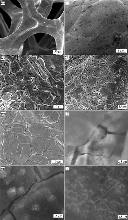
图1 泡沫铜、新镀薄膜Sn电极样品A、B和C以及经过100次充放电循环后的样品A、B和C的SEM像
Fig.1 SEM images of copper foam (a, b), fresh Sn thin film electrodes of samples A(c), B(d) and C(e) and samples A(f), B(g) and C(h) after 100 cycles of charge and discharge
2.2 薄膜Sn电极的XRD表征
图2所示为泡沫铜基底上薄膜Sn镀层样品A和B的XRD谱。从图2中可以看出,3种样品的XRD谱中均出现很强的Cu的特征衍射峰。3种样品中出现在30.60?、31.99?、43.81?、44.90?、55.32?和62.47?处为四方晶型Sn的特征衍射峰,这与JCPDS 04-0673对应。
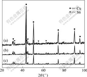
图2 薄膜Sn电极样品A、B和C的XRD谱
Fig.2 XRD patterns of Sn in film electrodes of samples A(a), B(b) and C(c)
2.3 薄膜Sn电极的电化学性能
图3所示为薄膜Sn电极的充放电测试曲线和循环性能曲线。从图3(a)可以看出,样品A首次放电时在0.41 V左右有一个有明显的平台,锂离子的嵌入大部分发生在这里。其放电平台出现滞后现象,表明样品A的首次嵌锂过程存在较大过电位,这与Li+向薄膜深层扩散比较困难有关。样品A的首次充放电容量分别为680.1和1 052.4 mA?h/g,然而经过几个循环容量迅速衰减。样品B的首次充放电容量分别为664.5和1 022.7 mA?h/g(见图3(b))。其放电平台较明显,经过几个循环后,容量衰减较快,但要慢于样品A的衰减速度。样品C的首次充放电容量分别为660.6和 1 724.4 mA?h/g。样品C存在很大的首次不可逆容量,且无明显的放电平台(见图3(c))。分析认为首次不可逆容量可能来自于两个方面:一是表面存在的少量氧化物(干燥过程中产生)与锂离子的反应;另一方面是电极的高表面积特性导致电解液在电极表面的分 发 解[16-18]。相比之下,样品C具有较好的循环性能。这可能是因为样品C镀层较薄,充放电过程中的体积膨胀所带来的结构变化会小一些。3种样品的脱锂过程中在高电位区都出现不可逆容量,可以认为是在0.8 V以上Sn更容易团聚引起巨大体积变化和龟裂,从而导致容量迅速衰减[19]。
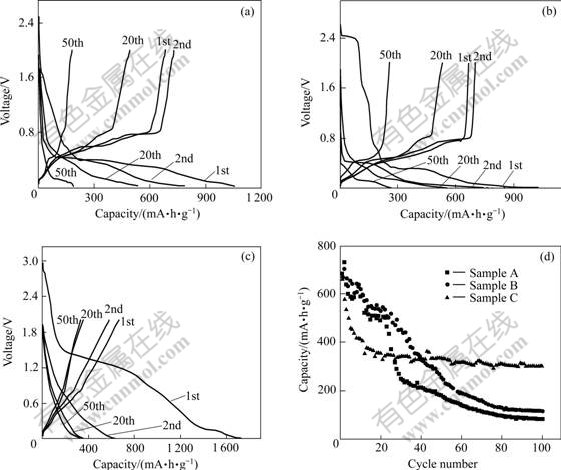
图3 薄膜Sn电极样品A、B和C的充放电测试曲线及循环性能曲线
Fig.3 Charge and discharge cycles curves of Sn thin film electrodes of samples A(a), B(b), C(c) and cycle performance(d)
从图3(d)中可以看出,尽管样品A和B具有较高的首次充电容量,然而容量迅速衰减,尤其是在第20个循环以后这一现象更加明显。而样品C的容量衰减相对比较缓和,第20个循环后没有明显的容量衰减,50次充放电循环后,容量保持在331.5 mA?h/g,比相关研究报道要好[14]。经过100次充放电循环,其容量保持在299.5 mA?h/g。
图4所示为样品C在0.1 mV/s的扫描速度下获得的循环伏安曲线。由图4可看出,在首次嵌锂过程中,电极在接近0.66 V和0.33 V出现两个的嵌锂峰,分别对应于不同嵌锂量合金贫锂相和富锂相的形成[20]。在电位回扫过程中,在0.62 V和0.83 V处的两个明显的氧化电流峰,对应于Li从合金中脱出的过程。经过三周的循环伏安扫描,电极的氧化电流峰基本无变化,分别在0.54、0.63和0.83 V处各显示一个氧化电流峰。
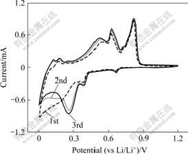
图4 样品C薄膜Sn电极的循环伏安曲线
Fig.4 Cyclic voltammogram curves of Sn thin film electrode of sample C
3 结论
1) 以泡沫铜为基底,用化学镀方法得到的薄膜Sn负极材料结构比较稳定。由于材料具有三维多孔骨架和表面岛状突起,将其作为锂离子电池负极材料时可以减小由于Sn在充放电过程中剧烈体积膨胀所带来的容量不可逆和循环性能差的影响。
2) 薄膜Sn负极材料的循环性能随着镀层厚度的减少而有所提高。较薄的镀层可以获得较好的循环性能。
REFERENCES
[1] INABA M, UNO T, TASAKA A. Irreversible capacity of electrodeposited Sn thin film anode[J]. J Power Sources, 2005, 146(1/2): 473-477.
[2] CHOI W, LEE J Y, JUNG B H, LIM H S. Microstructure and electrochemical properties of a nanometer-scale tin anode for lithium secondary batteries[J]. J Power Sources, 2004, 136(1): 154-159.
[3] PRIDATKO K I. Electrochemical insertion of lithium in thin tin films[J]. Russ J Electrochem, 2006, 42(1): 63-70.
[4] MORIMOTO H, TOBISHIMA S, NEGISHI H. Anode behavior of electroplated rough surface Sn thin films for lithium-ion batteries[J]. J Power Sources, 2005, 146(1/2): 469-472.
[5] WHITEHEAD A H, ELLIOTT J M, OWEN J R. Nanostructured tin for use as a negative electrode material in Li-ion batteries[J]. J Power Sources, 1999, 81/82: 33-38.
[6] ZHAO Z W, GUO Z P, WEXLER D, MA Z F, WU X, LIU H K. Titania nanotube supported tin anodes for lithium intercalation[J]. Electrochem Commun, 2007, 9(4): 697-702.
[7] PARK M S, WANG G X, KANG Y M, WEXLER D, DOU S X, LIU H K. Preparation and elctrochemical properities of SnO2 nanowires for application in lithium-ion batteries[J]. Angew Chem Int Ed, 2007, 46(5): 750-753.
[8] LEE K T, JUNG Y S, OH S M. Synthesis of tin-encapsulated spherical hollow carbon for anode material in lithium secondary batteries[J]. J Am Chem Soc, 2003, 125(19): 5652-5653.
[9] KE F S, HUANG L, JIANG H H, WEI H P, YANG F Z, SUN S G. Fabrication and properties of three-dimensional macroporous Sn-Ni alloy electrodes of high preferential (110) orientation for lithium ion batteries[J]. Electrochem Commun, 2007, 9(2): 228-232.
[10] HIRAI K, ICHITSUBO T, UDA T, MIYAZAKI A, YAGI S, MATSUBARA E. Effects of volume strain due to Li-Sn compound formation on electrode potential in lithium-ion batteries[J]. Acta Materialia, 2008, 56(7): 1539-1545.
[11] HU R Z, ZhANG L, LIU X, ZENG M Q, ZHU M. Investigation of immiscible alloy system of Al-Sn thin films as anodes for lithium ion batteries[J]. Electrochem Commun, 2008, 10(7): 1109-1112.
[12] WINTER M, BESENHARD J O. Electrochemical lithiation of tin and tin-based intermetallics and composites[J]. Electrochim Acta, 1999, 45(1/2): 31-50.
[13] JIANG T, ZHANG S C, QIU X P, ZHU W T, CHEN L Q. Preparation and characterization of silicon-based three- dimensional cellular anode for lithium ion battery[J]. Electrochem Commun, 2007, 9(5): 930-934.
[14] FAN X Y, ZHUANG Q C, JIANG H H, HUANG L, DONG Q F, SUN S G. Three-dimensional porous Cu6Sn5 alloy anodes for lithium-ion batteries[J]. Acta Phys-Chim Sin, 2007, 23(7): 973-977.
[15] TAMURA N, OHSHITA R, FUJIMOTO M, KAMINO M, FUJITANI S. Advanced structures in electrodeposited tin base negative electrodes for lithium secondary batteries[J]. J Electrochem Soc, 2003, 150(6): A679-A683.
[16] KIM J Y, KING D E, KUMTA P N, BLOMGREN G E. Chemical synthesis of tin oxide-based materials for Li-ion battery anodes[J]. J Electrochem Soc, 2000, 147(12): 4411-4420.
[17] LI H, SHI L H, LU W, HUANG X J, CHEN L Q. Studies on capacity loss and capacity fading of nanosized SnSb alloy anode for Li-ion batteries[J]. J Electrochem Soc, 2001, 148(8): A915-A922.
[18] YANG J, TAKEDA Y, IMANISHI N, YAMAMOTO Q. Tin- containing anode materials in combination with Li2.6Co0.4N[J]. J Electrochem Soc, 2000, 147(5): 1671-1676.
[19] COURTNEY I A, DAHN J R. Electrochemical and in situ X-ray diffraction studies of the reaction of lithium with tin oxide composites[J]. J Electrochem Soc, 1997, 144(6): 2045-2050.
[20] HUGGINS R A. Lithium alloy negative electrodes[J]. J Power Sources, 1999, 81/82: 13-19.
基金项目:国家自然科学基金资助项目(20763002)
收稿日期:2008-12-25;修订日期:2009-09-10
通信作者:李庆余,教授,博士;电话:0773-3310900;E-mail: sijianghu@yahoo.com.cn
(编辑 李艳红)

