

Structure optimization of porthole die based on aluminum profile extrusion process numerical simulation
WU Xiang-hong(�����)1, ZHAO Guo-qun(�Թ�Ⱥ)1, LUAN Yi-guo(���ݹ�)1,
LOU Shu-mei(¦��÷)1, MA Xin-wu(������)1
Engineering Research Center for Die & Mould Technology,
Shandong University, Ji��nan 250061, China
Received 28 July 2006; accepted 15 September 2006
Abstract:
Porthole die extrusion method is used to produce hollow aluminum profile. Due to the complexity of the porthole die structure and the material flow, it is very difficult to get ideal profile products with the firstly designed die structure. Finite volume numerical simulation was used to analyze the extrusion process of a hollow profile with porthole die and the problem of non-uniform material flow was found. Optimization was made to the originally designed die to solve the problem. Lower load, reasonable seaming location and even extruded forepart with uniform material flow in the optimized die extrusion were obtained. Guidelines to porthole die design were given and it is also concluded that finite volume method with Eulerian description avoids mesh regeneration and is suitable to numerical simulation of severe deformation processes, such as profile extrusion.
Key words:
porthole die; optimization; numerical simulation; aluminum profile extrusion;
1 Introduction
Porthole die extrusion is the most widely used method to produce aluminum hollow profile products. Porthole die structure parameters directly affect product quality. To analyze the reasonability of the die design it is important to get better comprehension of the material behavior in porthole dies.
Some investigators used experimental methods to quantify the deformation behavior of the material in porthole extrusion dies. KIM et al[1] have used AA1050 and AA1100 composed billet to investigate the metal flow in porthole die visibly and quantitatively. Due to the complexity and difficulty of experiments, many researchers have used finite element method (FEM) to simulate the extrusion process[2-6]. With Lagrange description, FEM elements will be distorted with material deformation. When FEM method is used in large or severe deformation processes, such as extrusion, frequent mesh regeneration is needed to rezone the distorted meshes and to continue the computation. The problems coming from mesh regeneration are data accuracy loss in data transfer and larger computation time. These problems limit the usage of FEM in simulation of extrusion processes to solid profile or hollow profile with simple geometry and thicker wall.
Some researchers have use the finite volume method(FVM) to simulate extrusion processes and have got certain successes [7-8].
Porthole die extrusion is more complicated in structure than usual extrusion processes. it is difficult to simulate with FEM and little research work has been done to analyze the porthole die structure reasonability with simulation method. The present paper uses finite volume method (FVM) with Eulerian description[9] to simulate a porthole die extrusion process and optimize the die structure. Simulation results show that ideal material flow state with uniform material deformation and exiting velocity as well as lower extrusion load is obtained using the optimized die structure.
2 Numerical model and process parameters
2.1 Numerical model
An aluminum hollow profile is produced using a flat porthole die[10]. An rectangular hollow profile extrusion is taken as the example. The flat porthole die is usually composed of a male mould (upper die) and a female mould (lower die). The upper die has portholes, portbridges and a die core, as shown in Fig.1. The lower die has a welding chamber, a die hole cavity. There is a bearing area in both dies, as illustrated in Figs.1 and 2. Fig.3 shows the structure components of the extrusion die.

Fig.1 Extrusion upper die

Fig.2 Extrusion lower die

Fig.3 Assembled model of extrusion die
2.2 Process parameters
The materials of H13 and A1100 are used for the extrusion dies and the billet, respectively. The billet is a cylinder with the diameter of 190 mm and the height of 70 mm. The extrusion speed is 3 mm/s and the total ram stroke is 36 mm. The initial temperatures of the dies and the billet are 400 �� and 450 ��, respectively. The friction model is the law of constant plastic shear friction and expressed as
��=m��yield (1)
where �� is frictional shear stress, m is friction factor (here supposed to be 0.5), and ��yield is the shear yield stress. To save computational time and resources cost, different element sizes for different periods are used, 4 mm for 0-80% stroke, 2 mm for 80%-100% stroke.
The material flow stress of AA1100 material is as follows:
![]() (2)
(2)
where the flow constant C and the strain-hardening exponent N are dependent on temperature and effective strain of the material, and S is the minimum yield stress of the material.
3 Results and analysis
3.1 Simulation results for original die
When the stroke reaches 36 mm, the extrudate��s shape of the original die design is shown in Fig.4, from which we can see that the material flow velocity at the rectangle��s short side is obviously faster than that at the long side. Non-uniform material flow occurs. It should be corrected to avoid extrudate��s quality shortcomings, such as warping. The reason of non-uniform material flow probably relates to the factors influencing the material flow velocity, including the shape, size and location of the portholes, the shape and size of the welding chamber, the length of the bearing land, and the channel shape from the portholes to the bearing land through which material flows.

Fig.4 Extrudate��s shape of original die design
3.2 Optimization of die structure
According to above problems existing in the original die design, the die structure is optimized as shown in Fig.5. The channels at the rectangle��s long sides are changed to be linear to assure the similar flow resistance before material enters the bearing land and the porthole shapes at the long sides are widened to get the geometrical similarity between the collocation of the portholes and the profile shapes.

Fig.5 Optimized extrusion upper die
4 Results of optimization
4.1 Even forepart
The simulation results for the optimized die show that uniform material flow can be obtained and a profile with an even forepart is extruded, as shown in Fig,6. The optimized die structure not only changes the material distribution through changing the porthole shape but also changes the material flow resistance through changing the channel shape.

Fig.6 Even forepart in optimized die
4.2 Lower load-stroke
Fig.7 shows the load-stroke curves of two die designs. The curve peak values for both die designs occur after the material has entered the bearing land. The peak value of the original die is 6.32 MN, while the peak value of the optimized die is 3.08 MN and is decreased by 3.24 MN (48%) than that of the original die. A lower extrusion force will greatly prolong extrusion die life. The optimized die structure changes material flow resistance and has a significant influence on the die load.
4.3 Uniform material flow velocity distribution
Fig.8 shows the material flow velocity distributions of two die designs. It can be seen that the material flow velocity distribution of the optimized die is more uniform than that of the original die in the whole extrusion process. More uniform velocity distribution assures that the material flows out of the die exit uniformly and avoids product shortcomings.
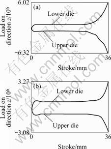
Fig.7 Load��stroke curves of two die designs: (a) Original die; (b) Optimized die

Fig.8 Materials flow velocity of two die designs: (a) Original die; (b) Optimized die
4.4 Suitable seaming line location
In the original die the seaming line is located in the longer side of the rectangle, as shown in Fig.9(a). The seaming line in the optimized die is near the diagonal of the rectangle, as shown in Fig.9(b). This fact implies that the location and shape of the portholes in the optimized die are more geometrically similar with the profile��s shape so as to form a beneficial factor for uniform material flow.
4.5 Uniform effective strain rate distribution
Fig.10 shows the effective strain rate distributions of two die designs. In the original die design, the effective strain rate distribution is not uniform and the peak value locates at the point where the material enters the welding chamber from the portholes. While in the optimized die design, the effective strain rate distribution is much more uniform and the peak value of strain rate locates near the seaming line in the welding chamber. The peak value decreases by 71%, from 4.303 in the original die to 1.243 in the optimized die.

Fig.9 Seaming line locations of two die designs: (a) Original die; (b) Optimized die
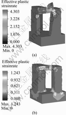
Fig.10 Effective strain rate distributions of two die designs: (a) Original die; (b) Optimized die
5 Conclusions
The extrusion process of an aluminum hollow profile with porthole die is simulated using finite volume method based software Msc/SuperForge. The feasibility of the porthole die structure is analyzed by simulation results. The die structure is optimized to solve the uneven material flow problem existing in the original die design. Simulation results show that ideal material flow with uniform material deformation, uniform exiting velocity and lower extrusion load is obtained using the optimized die design. In a porthole die extrusion process, the die structure parameters, such as the shape and size of material flow channel, portholes, welding chamber and bearing land, are main factors influencing material flow. Among these factors, the geometrical similarity between portholes and profile as well as the material flow channel resistances is the key point for uniform material flow. Uniform material flow also improves the deformation uniformity and decreases the die load. Finite volume method with Eulerian description avoids mesh regeneration, so it has an obvious advantage in numerical simulation of severe deforming processes, such as profile extrusion.
References
[1] KIM Y T, KEISUKE I, TADASU M. Metal flow in porthole die extrusion of aluminium [J]. J Material Processing Technology, 2002, 121: 107-115.
[2] ZHOU J, LI L, DUSZCZYK J. 3D FEM simulation of the whole cycle of aluminum extrusion throughout the transient state and the steady state using the updated Lagrangian approach [J]. J Materials Processing Technology, 2003, 134: 383-397.
[3] CHANDA T, ZHOU J, DUSZCZYK J. FEM analysis of aluminum extrusion through square and round dies [J]. Materials and Design, 2000, 21: 323-335.
[4] DUAN Xin-jian, VELAY X, SHEPPARD T. Application of finite element method in the hot extrusion of aluminum alloys [J]. Materials Science and Engineering A, 2004, A369: 66-75.
[5] LI Q, SMITH C J, HARRIS C, et al. Finite element investigations upon the influence of pocket die designs on metal flow in aluminum extrusion Part I. Effect on pocket angle and volume on metal flow [J]. J Materials Processing Technology, 2003, 135: 189-196.
[6] LI Q, SMITH C J, HARRIS C, et al. Finite element modeling investigations upon the influence of pocket die designs on metal flow in aluminum extrusion(Part ��): Effect of pocket geometry configurations on metal flow [J]. J Materials Processing Technology, 2003, 135: 197-203.
[7] MEHTA B V, IBRAHIM Al-Zkeri, GUNASEKERA J S, et al. 3D flow analysis inside shear and streamlined extrusion dies for feeder plate design [J]. J Materials Processing Technology, 2001, 113: 93-97.
[8] WILLIAMS A J, CROFT T N, CROSS M. Computational modelling of metal extrusion and forging process [J]. J Materials Processing Technology, 2002, 125-126: 573-582.
[9] VERSTEEG H, An Introduction to Computational Fluid Dynamics: the Finite Volume Method[M]. New York: Longman Scientific & Technical, 1995.
[10] LIU Jing-an. Aluminum Profile Extrusion Die Design, Manufacture, Usage and Maintaining [M]. Beijing: Metallurgical Industry Press, 2002. (in Chinese)
(CHEN Ai-hua)
Foundation item: Project(50425517) supported by National Science Foundation for Distinguished Young Scholars of China; Project(50375087) supported by the Natural Science Foundation of China; Project(Q2004f01) supported by Natural Science Foundation of Shandong Province, China
Corresponding author: ZHAO Guo-qun; Tel: +86-531-88393238; E-mail: Zhaogq@sdu.edu.cn
