
J. Cent. South Univ. (2016) 23: 269-276
DOI: 10.1007/s11771-016-3070-8

Numerical study on forming complex fitting body on end of integrated stainless steel pipe without welds
Zhang Da-wei(�Ŵ�ΰ)1, 2, Zhao Sheng-dun(������)1
1. School of Mechanical Engineering, Xi��an Jiaotong University, Xi��an 710049, China;
2. Department of Mechanical, Materials and Manufacturing Engineering,
University of Nottingham, Nottingham, NG7 2RD, UK
 Central South University Press and Springer-Verlag Berlin Heidelberg 2016
Abstract:
It is necessary to use the integrated stainless steel pipe having two fitting bodies without welds while train travelling at high speed. In order to form this type of integrated stainless steel pipe, the method of preforming combined finish forming process is developed. The preforming process is characterized by flaring combined upsetting for left fitting body which is like a flange, and is characterized by tube axial compressive process under die constraint for right fitting body which is like a double-wall pipe. The finite element simulations of the processes are carried out by software package DEFORM, and the results indicate that: 1) left or right fitting body can be formed by a two-step forming process without folding and under-filling defects; 2) by using two-step forming, strain and stress in left fitting body are larger than those in right fitting body, and deformation in right fitting body is more homogenous than the deformation in left fitting body; 3) two or more preforming steps may be needed for left fitting body considering the distributions of strain and stress.
Key words:
plastic forming; hot forming; flange joint; integrated steel pipe; finite element analysis��
1 Introduction
Flange joints have a wide application in industry, such as chemical, nuclear, water supply [1-2]. These are also widely used in hydraulic and gas piping systems of railway vehicles, such as the pipe line of braking system, as shown in Fig. 1(a). The stainless steel pipe used in the railway vehicle has two fitting bodies on the end, which connect to another pipe or valve by using flange disk. The flange disk covers the fitting body, as shown in Fig. 1(b).
One kind of the pipes is shown in Fig. 2, which includes one convex end (similar to flange) and one flat end (similar to double-wall pipe). The thickness of the end sections is different from the pipe, thicker than the wall thickness of the pipe. Usually, the fitting bodies are manufactured by metal cutting process, and then the fitting bodies are welded onto the end of stainless steel pipe. However, with the increase of travelling speed, the requirement of performance for the pipe system also increases. The welds between pipe and fitting body are prone to crack while train travelling at high speed. If the integrated stainless steel pipe having two fitting bodies without welds is used in the piping system, above problem caused by welding can be solved. However, it is difficult to form the fitting bodies from the ends of pipe due to complex shape and end thickening sharply. Thus, it is necessary to develop a new method to form fitting body from the end of pipe without welds.
However, by now most researchers emphasized their works on study of bolt preload [1-2], simulation of the bolt-up process [3], and analysis of relaxation behavior in the pipe flange joint [4]. The performance flange pipe joint is also concerned, especially under internal pressure coupled thermal loading [5]. The welding process and its effect on the connection have also been investigated because the fitting body or flange was welded onto the pipe [6]. The literature about the plastic forming for the stainless steel pipe with fitting bodies from a pipe is scare. Hu and Wang [7] presented a multi-step upsetting method to form a flange on the end of pipe. The process needs eleven steps and has an ejector in lower die to push the other end of pipe, so the method may not suit to forming flange from a long pipe or two flanges on both end. A tube axial compressive process with free dieless deformation can form a double-wall pipe from pipe-billet [8-9]. However,the thickness of pipe will not increase. so, it is difficult to form the thickened double-wall pipe as the right fitting body shown in Fig. 2.
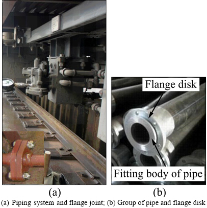
Fig. 1 Flange joints in railway vehicle:
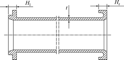
Fig. 2 Structure of pipe with fitting bodies
It is difficult to form a flange from pipe-billet where the ratio of thickness of flange to wall thickness of the pipe-billet is 1.5, and thus the eleven-step upsetting process was developed by Hu and Wang [7]. In the present work, the ratios, i.e. Hl/t and Hr/t shown in Fig. 2, are twice those in Ref. [7]. In order to prevent folding, the upsetting ratio of length of deformed pipe to wall thickness of pipe-billet should be less than three, but the upsetting ratios for left and right fitting bodies are both greater than ten. Thus, the previous plastic forming processes are difficult to form the fitting bodies from the ends of pipe. A method of two-step hot forming process to form the fitting body from the pipe is developed in this work. Firstly, one fitting body on the end is formed by preforming and finish forming, and then the other fitting body on the other end is formed by two steps. Only local section of pipe is heated in the forming process. The preforming process for left fitting body is similar to flaring combined upsetting process. The preforming process for right fitting body is similar to tube axial compressive process under die constraint. The computer aided design and computer aided engineering are widely used in process planning, analyzing forming process, parameters optimization with low cost and short cycle [10-12]. Thus, the computer aided engineering (CAE) is also used in this work. In order to analyze the metal forming in the processes and examine the feasibility of the new method, finite element simulations of the processes are carried out by software package DEFORM.
2 Description of forming processes for different fitting bodies
The pipe-billet is prone to bulking under axial compression, and then folding will be caused when the processing continues. Increasing the die constraint, the pipe-billet is also prone to destabilize in the die cavity, which is not good to later process or to forming folding. Even two-step forming process is adopted, it also needs a suitable process control to prevent folding due to the long deformed section, thin wall of pipe-billet, and complexity of fitting body.
The length of integrated stainless steel pipe shown in Fig. 2 is from several hundred millimeters to several thousand millimeters, and the lengths (Hl, Hr) of fitting body are about 10 mm. The initial length of pipe-billet is determined according to volume constancy. In the forming process, only local section of pipe-billet is heated to form fitting body, and the unheated section is clamped and fixed. Two-step forging process is used to form fitting body, but the process for left fitting body is different from that for right fitting body due to different geometries.
Figure 3 illustrates the scheme of two-step forming process for left fitting body that is like a flange. The first step is preforming which is similar to the flaring combined upsetting process, and two preforming dies move in the same direction after two dies are closed, as shown in Fig. 3(a). The second step is finish forming, and only finish forging die 1 moves along the axis after two dies are closed, as shown in Fig. 3(b), where the die 1 is similar to female die in the ordinary forging process.
Figure 4 illustrates the scheme of two-step forming process for right fitting body that is like a double-wall pipe. The first step is also the preforming, but it is similar to the tube axial compressive process under dieconstraint, and the preforming die 1 (similar to fillet die in tube axial compressive process) moves along the axis, as shown in Fig. 4(a). This motion of the die is different from that in the tube axial compressive in Refs. [8-9]. The second step is also finish forming, and finish forming die 1 moves along the axis yet, as shown in Fig. 4(b), where the die 1 is similar to female die and the die 2 is similar to male die in the ordinary forging process.
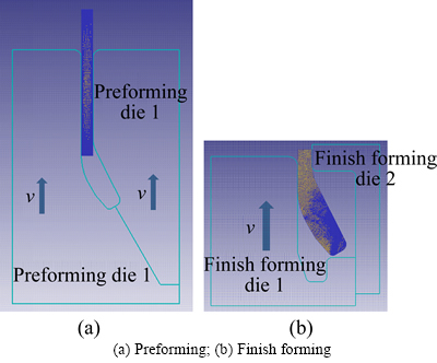
Fig. 3 Scheme of two-step forming process for left fitting body:
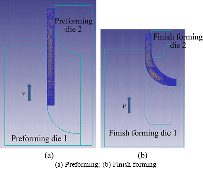
Fig. 4 Scheme of two-step forming process for right fitting body:
3 Finite element models of forming processes
Shape of the integrated stainless steel pipe forming by plastic forming process is shown in Fig. 2. The sizes used in this work are that the internal diameter of pipe is 36 mm, the wall thickness of pipe is 3 mm, and the out diameter of fitting bodies is 60 mm. The internal diameter and wall thickness of pipe-billet are the same as those of the middle section pipe shown in Fig. 2, and the initial length of pipe-billet is determined according to volume constancy.
The two-dimensional finite element (2D-FE) model is adopted in this work due to axisymmetric forming problem. Based on the 2D-FE model of tube extrusion process developed in software package DEFORM [13], the 2D-FE models for the forming processes described in Section 2 are developed by changing geometric models and boundary conditions, as shown in Figs. 3 and 4.
In the forming process, only local section is heated, and the length of heated section is a little greater than length of section to form fitting body (Hl or Hr). There is a temperature and deformation transitional area from heated section to unheated section. However, the heated section will be quickly heated by using induction heating method, and the processing time for performing or finish forming is short. In addition, the strength and length of unheated section are much greater than those of heated section, and the unheated section is clamped and fixed to apply a strong restriction to heated section. Thus, the influence of transitional area is little, and then only the heated section is modeled. In the FE model, the nodes at the plane connecting unheated section are restrained. In the forging process, the speed of die is fast and the performing and finish forming are both less than 1 s, and the dies will be preheated before forging. so, the process is considered an isothermal process.
The dies are treated as rigid bodes, while the pipe-billet as plastic body. The material of the pipe-billet is AISI-321 stainless steel, whose material properties come from material library in DEFORM. The von Mises yielding criterion is adopted in the FE models. In order to investigate the formability of workpiece and evaluate the possibility of crack, damage index Df is introduced and defined as Eq. (1), which is developed from Cockcroft & Latham criterion.
 (1)
(1)
where s* is the maximum tensile stress;  is the effective stress;
  is the effective strain; s1 is the maximum principle stress.
The form of model is successfully used to predict ductile failure of hot forming for pancake forgings [14] and to evaluate forming quality of valve forging [15]. The micro cracks are initiated if Df is up to critical value Dc [16]. The Dc may vary between Dc 0 for pure brittle fracture to Dc1 for pure ductile fracture [16]. However, the critical value of damage is sensitive to the working temperature in hot forming process. The critical value will be great at elevated temperature, and the critical value is greater than 1 at 955 ��C for Ti-6Al-4V alloy [14]. The larger the damage index is, greater the possibility of crack is.
A velocity-dependent shear friction model expressed by Eq. (2) [17-18] widely used in hot forming is employed to describe the friction at the interface between pipe-billet and die. The friction factor is 0.2-0.3 in lubricated hot forming process recommended by DEFORM manual [19], and thus 0.2 is adopted in the present work.
 (2)
(2)
where fs is the frictional stress; K is the shear yield stress of the metal; m is the friction factor, 0��m��1; ur is the relative velocity; u0 is an arbitrary constant, much smaller than relative velocity.
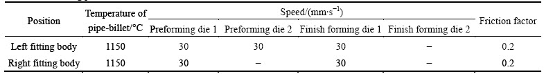
AISI-321 stainless steel is an austenitic stainless steel, and the working temperature 1150 ��C is adopted according to handbooks [20]. The loading speed of die is taken to be 30 mm/s. The parameters used in the model are summarized in Table 1.
Table 1 Processing parameters used in FE model
4 Results and discussion
4.1 Shape and deformation
The folding defect is prone to occurrence in the process. The preforming shape determined by finish forming is difficult to form by one step preforming. The simulation results indicate that folding and matte surface may appear in preforming process, and the folding defect in finish forming is often caused by a matte surface of preform, as shown in Fig. 5. Thus, the preform with smooth surface and without folding should be considered firstly, and then the preforming and finishing forming processes are considered together. The preforming die structures are modified according to the results obtained by finite element analysis (FEA). The geometry evolution under a suitable die structure in the two-step forming process for left and right fitting bodies is analyzed as follows.
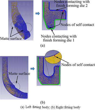
Fig. 5 Matte surface and folding in processes:
Figure 6 illustrates the geometry evolution in the two-step process for left fitting body. It can be found from Fig. 6(a) that the deformation behavior presents the flaring characteristic at initial stage, but the flaring combined upsetting characteristic would be present after the end plane of pipe-billet contacts the die cavity. The forming load is small at the flaring stage and increases at the flaring combined upsetting stage. The FEA results indicate that the preform can be obtained without matte surface and folding. Finish forming process shown in Fig. 6(b) is similar to the ordinary forging process. No forming defects such as folding and under-filling are observed according to FEA results.
Figure 7 illustrates the geometry evolution in the two-step process for right fitting body. It can be found from Fig. 7(a) that the deformation behavior is similar to that in tube axial compressive process with free dieless deformation because of non-constraint on the end plane of pipe-billet at the initial stage, and the thickness has little change and the forming load is small at this stage. However, the upsetting combined tube axial compression has been present at late stage, and the forming load becomes to increase due to the die constraint. The matte surface and folding do not appear in the preform for right fitting body according to the FEA results.
The finish forming process of right fitting body can be divided into three stages according to the deformation characteristics shown in Fig. 7(b). The pipe-billet bends at the first stage, and then the shape is kept the same at the second stage. When the pipe-billet contacts the lower surface of cavity of the finish forming die 1, the pipe-billet starts to yield again. This is the third stage, and the die cavity is filled and the expected shape of right fitting body is obtained at the third stage. No defects about flow line and cavity fill are observed from the simulation results.
4.2 Forming load
In the forming process of left fitting body, the forming load along axis of pipe is shown in Fig. 8. In the preforming process, forming load of the preforming die 2 is much less than that of the performing die 1, as show in Fig. 8. At the flaring forming stage, the maximal force of the preforming dies is about 10 kN. At the flaring combined upsetting stage, the forming load is less than 250 kN generally, but the maximal force is greater than 600 kN at the last 0.01 s for complete die filling. The forming load of the preforming die 2 is nearly 1/2-2/3 of the load of the preforming die 1 and lasts for 0.01 s.
It can be seen from the Fig. 8 that the forming loads of two dies are much closer in finishing forming process. The forming loads of finish forming dies raise to about 1000 kN in the last 0.0003 s. These are also similar to that in ordinary forging process.
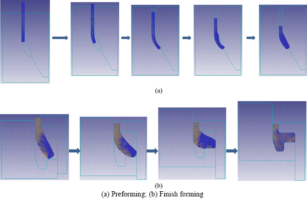
Fig. 6 Shapes of left fitting body at chosen stages:
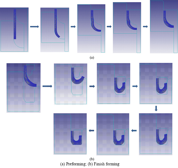
Fig. 7 Shapes of right fitting body at chosen stages:
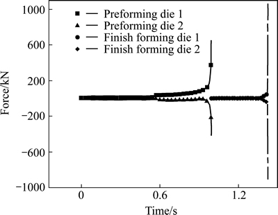
Fig. 8 Axial load in forming process of left fitting body
Figure 9 illustrates the forming load along axis of pipe in the forming process of right fitting body. The forming load of the preforming die 2 is less than that of the performing die 1 and the forming load of the finish forming die 2 is also less than that of the finish forming die 1, as shown in Fig. 9. At the initial stage of preforming process, where there is non-constraint on the end plane of pipe-billet, the maximal force of preforming dies is less than 30 kN. The load-time curve at upsetting combined tube axial compressive stage is similar to that in a forging process, but the force is smaller due to under-filling. Finally, the maximal load is about 260 kN for preforming die 1 and is about 190 kN for preforming die 2.
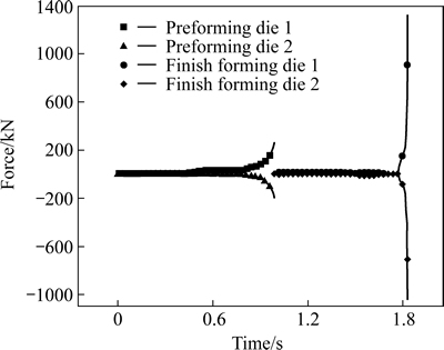
Fig. 9 Axial load in forming process of right fitting body
In Section 4.1, the finish forming process of right fitting body is divided into three stages. At the first stage, the forming load increases but decreases after pipe-billet contacts finish forming die 1 steadily due to free bending deformation. When the arc-shaped surface of the finish forming die 2 contacts the pipe-billet, the forming load increases again, but the forming load decreases to zero after the contact area reachs to a maximum. The reason is that the die constraint is small and the deformation reduces. There is no deformation at the second stage, and the shape is kept the same. The forming load is less than 30 kN at the first stage, and the forming load is zero at the second stage.
The third stage starts after the pipe-billet contacts the lower surface of cavity of finish forming die 1, and the forming load increases sharply. The forming load is less than 375 kN for finish forming die 1 and is less than 280 kN for finish forming die 2 before the corner is filled. In the last 0.0075 s of the finish forming process, the forming load is great than 1300 kN for the finish forming die 1 and is greater than 1000 kN for the finish forming die 2.
4.3 Distribution of variables
The integrated stainless steel pipe having two fitting bodies can be formed from one pipe-billet without folding and under-filling defects according to the above analysis. The processing parameters and die structures may be suitable for manufacturing the left fitting body and right fitting body. The distributions of strain, stress and damage in final forging are analyzed in further.
Figure 10 illustrates the distributions of effective strain in the left and right final forgings. It can be seen from Fig. 10 that the deformation in right fitting body is more homogenous than the deformation in left fitting body, but the more severe deformation occurs in the left fitting body. The length, internal and out diameters for both fitting bodies are the same, but the volume for the left fitting body is greater than that for the right fitting body. Thus, the left fitting body has the inhomogenous deformation.
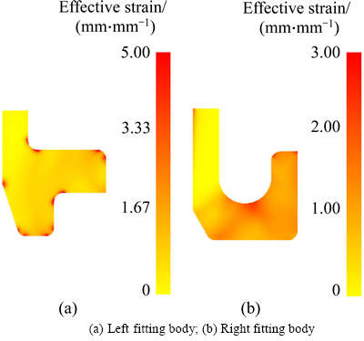
Fig. 10 Distribution of effective strain in final forging:
For the left fitting body, the effective strain in corner area is much greater than that in other area, as shown in Fig. 10(a). The stress concentration in corner area is also presented according to Fig. 11(a). These phenomena are not notable for right body. Comparison between Fig. 10 and Fig. 11 indicates that distribution of effective stress filed is similar to that of effective strain field. The effective stress filed in the right fitting body is also more homogenous than that in the left fitting body, and the effective stress is also small in the right fitting body. In order to obtain homogenous deformation and reduce stress concentration, more than two forming steps are needed to form left fitting body due to large deformation.
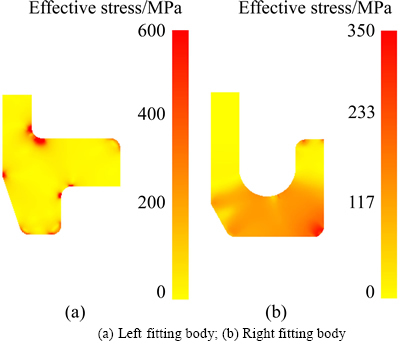
Fig. 11 Distribution of effective stress in final forging:
The maxima of damage for the left and right fitting bodies both appear in outside, as shown in Fig. 12. The maximum of damage in the right fitting body is twice that in the left fitting body, but the value may be less than the critical value at elevated temperature (1150 ��C).
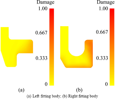
Fig. 12 Distribution of damage index in final forging:
5 Conclusions
1) The integrated stainless steel pipe having two fitting bodies without welds can be formed from one pipe-billet by multi-step hot forming process. The developed processes are characterized by flaring combined upsetting preforming process for the left fitting body and tube axial compressive process under die constraint for the right fitting body. The developed processes are investigated by FEA.
2) In the finish forming process, the folding defect is often caused by a matte surface of preform. Both fitting bodies can be formed by two-step forming process taking into consideration flow line and cavity fill.
3) There exists a difference of forming load between two dies in the preforming process for the left fitting body, but the finish forming process is similar to the ordinary forging process. However, the forming loads of loading dies are both greater than the load of fixed dies in the preforming and finish processes for the right fitting body.
4) Compared with the formed right fitting body, the formed left fitting body has the inhomogenous deformation and the stress concentration in corner area is due to more metal flow. Thus, considering the deformation uniformity, the forming process for left fitting body may need more than two steps.
5) The pipe-billet clamping and fixing system and the die replacing system should be investigated, and the influence of unheated section (especially the transitional area) on the heated section in the process should be studied in the future.
References
[1] SAWA T, OGATA N, NISHIDA T. Stress analysis and determination of bolt preload in pipe flange connections with gaskets under internal pressure [J]. J Pressure Vessel Technol, 2002, 124(4): 385-396.
[2] ABID M, HUSSAIN S. Bolt preload scatter and relaxation behaviour during tightening a 4 in-900# flange joint with spiral wound gasket [J]. Proc Inst Mech Eng E: J Process Mech Eng, 2008, 222(2): 123-134.
[3] FUKUOKA T, TAKAKI T. Finite element simulation of bolt-up process of pipe flange connections with spiral wound gasket [J]. J Pressure Vessel Technol, 2003, 125(4): 371-378.
[4] ABID M, HUSSAIN S. Relaxation behaviour of gasketed joints during assembly using finite element analysis [J]. Sadhana, 2010, 35(1): 31-43.
[5] ABID M, KHAN K A, CHATTHA J A. Performance testing of gasketed bolted flange pipe joint under combined pressure and thermal loading [J]. Exp Tech, 2011, 35(6): 35-37.
[6] ABID M, SIDDIQUE M, Numerical Simulation to study the effect of tack welds and root gap on welding deformation and residual stresses of a pipe-flange joint [J]. Int J Pressure Vessels Piping, 2005, 82(11): 860-871.
[7] HU X L, WANG Z R. Numerical simulation and experimental study on the multi-step upsetting of thick and wide flange on the end of a pipe [J]. J Mater Process Technol, 2004, 151(1/2/3): 321-327.
[8] SUN Z C, Yang H. Free deformation mechanism and change of forming mode in tube inversion under conical die [J]. J Mater Process Technol, 2006, 177(1/2/3): 171-174.
[9] SUN Z C, Yang H. Study on forming limit and feasibility of tube axial compressive process [J]. J Mater Process Technol, 2007, 187/188: 292-295.
[10] FENG W, HUA L, HAN X H. Finite element analysis and simulation for cold precision forging of a helical gear [J]. Journal of Central South University, 2012, 19(12): 3369-3377.
[11] LI J C, WANG B, ZHOU T G. Analysis and optimization of variable depth increments in sheet metal incremental forming [J]. Journal of Central South University, 2014, 21(7): 2553-2559.
[12] NGUYEN D T, DINH D K, NGUYEN H M T, BANH T L, KIM Y S. Formability improvement and blank shape definition for deep drawing of cylindrical cup with complex curve profile from SPCC sheets using FEM [J]. Journal of Central South University, 2014, 21(1): 27-34.
[13] Zhang Da-wei, Zhao Sheng-dun, Zhu Cheng-cheng, Zhang Jun, Hu Yang-hu, Duan Li-hua. Finite element analysis of piercing process of piercing extrusion for titanium alloy solid ingot [J]. Rare Metal Mater Eng, 2016, 45(1) (in Press). (in Chinese).
[14] SEMIATIN S L, GOETZ R T, SHELL E B, SEETHARAMAN V, GHOSH A K. Cavitation and failure during hot forging of Ti-6Al-4V [J]. Metall Mater Trans A, 1999, 30A: 1411-1424.
[15] ZHANG D W, YANG H, SUN Z C. 3D-FE modelling and simulation of multi-way loading process for multi-ported valve [J]. Steel Res Int, 2010, 81(3): 210-215.
[16] LEMAITRE J. A course on damage mechanics [M]. Berlin: Springer-Verlag, 1992.
[17] KOBAYASHI S, OH S I, ALTAN T. Metal forming and the finite-element method [M]. New York: Oxford University Press, 1989.
[18] TAN X. Comparisons of friction models in bulk metal forming [J]. Tribol Int, 2002, 35: 385-393.
[19] SFT Inc. DEFORMTM Integrated 2D-3D Version 10.2 and DEFORMTM v11.0 (Beta) User��s Manual [M]. Columbus, Ohio: Scientific Forming Technologies Corporation, 2011.
[20] Gan Yong, Tian Zhi-ling, Deng Han, Feng Di, Wang Xin-lin. China materials engineering canon: Volume 3 [M]. Beijing: Chemical Industry Press, 2005. (In Chinese)
(Edited by YANG Hua)
Foundation item: Project(51305334) supported by the National Natural Science Foundation of China; Project(51335009) supported by the National Natural Science Foundation of China for Key Program; Project(CXY1442(4)) supported by the Science and Technology Planning Project of Xi��an, China; Project supported by Shaanxi Province Postdoctoral Science Research Program of China
Received date: 2014-12-15; Accepted date: 2015-04-20
Corresponding author: ZHANG Da-wei, PhD, Lecturer; Tel: +86-29-82668607; Fax: +86-29-82665204; E-mail: zhangdawei2000@mail.xjtu.edu.cn; dawei.zhang@nottingham.ac.uk
Abstract: It is necessary to use the integrated stainless steel pipe having two fitting bodies without welds while train travelling at high speed. In order to form this type of integrated stainless steel pipe, the method of preforming combined finish forming process is developed. The preforming process is characterized by flaring combined upsetting for left fitting body which is like a flange, and is characterized by tube axial compressive process under die constraint for right fitting body which is like a double-wall pipe. The finite element simulations of the processes are carried out by software package DEFORM, and the results indicate that: 1) left or right fitting body can be formed by a two-step forming process without folding and under-filling defects; 2) by using two-step forming, strain and stress in left fitting body are larger than those in right fitting body, and deformation in right fitting body is more homogenous than the deformation in left fitting body; 3) two or more preforming steps may be needed for left fitting body considering the distributions of strain and stress.
