
Trans. Nonferrous Met. Soc. China 24(2014) 1521-1530
Large-scale manufacturing of aluminum alloy plate extruded from subsize billet by new porthole-equal channel angular processing technique
Lei SHI1, He YANG1, Liang-gang GUO1, Li DANG1, Jun ZHANG2
1. State Key Laboratory of Solidification Processing, School of Materials Science and Engineering, Northwestern Polytechnical University, Xi��an 710072 China;
2. China National Heavy Machinery Research Institute Co., Ltd, Xi��an 710032, China
Received 27 April 2013; accepted 9 August 2013
Abstract:
To manufacture plate by the combination of equal channel angular processing (ECAP) and porthole die extrusion techniques, a novel technique, namely portholes-equal channel angular processing (P-ECAP), was studied. Extrusion of AL6005A plate used for the bullet train plate was investigated by finite element method. The relevant porthole dies involving ECAP technique in channels were designed. Dimensional changes in the scrap part of the extrudate obtained after extrusion from the P-ECAP die, with different channel angles, were predicted. Effects of the channel angle and extrusion speed on the maximum temperature of the workpiece and other field variables were evaluated. At the channel angle of 160�� of P-ECAP dies, the extrudate exhibited the optimal performance and the least amount of extrudate scrap was obtained. The optimal extrusion speed was 3-5 mm/s. Moreover, with the increase in ram speed from 1 to 9 mm/s, the peak extrusion load increased by about 49% and the maximum temperature was increased by about 70 ��C. The effective strain exhibited ascending trend in the corner of the ECAP deformation zone. In the solder seam and the side of die bearing of extrudate, the maximum principal stresses were tensile stress.
Key words:
subsize billet; porthole die; equal channel angular processing (ECAP); extrusion;
1 Introduction
Rolling is a traditional large-scale plate production technique; however, there are a number of steps involved in the process of rolling to manufacture plate [1,2]. Moreover, there are certain inefficiencies and disadvantages of rolling process. In contrast, the aluminum (Al) alloys plate can be manufactured in one step by extrusion technique. Recently, extensive research efforts have been devoted to develop novel extrusion methods because of the significant increase in the use of Al extrusions for wide range of applications. The one-shot die pressing is a new process to produce Al alloys extrusion plate on large scale with high material utilization, less number of steps, and high efficiency, leading to the production of high quality products. This is due to the triaxial compression stress state of the workpiece. In contrast, the rolling process involves biaxial compression stress state.
It is well-known that Al alloy is extremely difficult to extrude, in particular, when wide range of extrudate cross-section shapes is obtained and the ratio of flakiness on shape of the extrudate is very large [3]. The extrusion load required in traditional processing is extremely high. Extrusion load of expanding extrusion is smaller than that in the traditional processing because of small extrusion ratio. However, there is some gross imperfection on the edge of expanding extrusion product. For Al alloy, the optimization of the extrusion process and die structure for obtaining a reasonable extrusion speed without affecting extrudate surface and microstructural quality is extremely complex. For some special solid profiles with large spread, the technique may need the plane diffluent and expanding extrusion technology to save energy, which increases design difficulties. Therefore, combination of significantly effective techniques is highly desirable because of the above mentioned complicated influencing factors. In practice, traditional ��try-and-error�� method is always used for die design and process optimization, which is costly and results in the wastage of production time or extension of research and development cycle. Therefore, process simulation technology based on finite element method (FEM) is a viable alternative predictive tool for preliminary engineering in this new research area.
Equal channel angular pressing (ECAP) is attracting significant attention in several severe plastic deformation (SPD) [4] processing methods which are now available. In this method, the sample in the form of a relatively short rod is pressed through a die constrained within a channel bent through an angle [5,6]. The ECAP process developed by SEGAL [7,8] is an ingenious method of SPD which can be applied to numerous materials with enormous advantages over the other methods of deformation. According to Refs. [9-15], ECAP process has been successfully used to produce nanostructure metal materials. For example, the yield stress after six pressings was 425 MPa in the post-ECAP aged 6061 Al alloy; however, it was 275 MPa in the ECAP 6061 alloy without a special heat treatment before and after ECAP [16].
Significant research efforts have been devoted to change and improve the ECAP die structure. LI et al [14] demonstrated that a shorter outlet channel led to a longer steady-state region and a lower working load, but there was a higher tendency of upward bending of the deformed workpiece. YOUNG et al [17] designed continuous ECAP process for manufacturing a microstructure- refined bolt, and showed that the manufacturing was possible using a proposed die set-up with a conventional material. Thus, the above mentioned literature studies have confirmed that the ECAP process is an effective approach for producing bulk fine grain structured materials [15]. However, in-depth research on the deformation homogeneity within the flat square cross-section of the samples obtained from porthole die involving ECAP process in channels to achieve continuous production has not been investigated.
Limited attention has been paid to the application of ECAP in porthole die. Compared with the proven technique of ECAP, the application of ECAP in porthole die is a novel research area. Few practical applications employ ECAP technique to obtain large ratio of length to width on shape of the extrudate, such as plate for bullet train. Importantly, conventional ECAP is a discontinuous process involving a repetitive sequence in which the workpiece is inserted into the die, pressed through the die, removed, and then reinserted to impose an even higher strain. This indicates that, although ECAP is an effective processing tool for laboratory research, it is labor-intensive and not easily adapted for use in large-scale manufacturing [12].
Porthole-ECAP (P-ECAP) die is a combination of the two techniques of ECAP and porthole die. YANG et al [13] designed a new die of P-ECAP. In this study, a pair of channels with an angle set up in two portholes of a die was employed. It avoided some of the disadvantages of ECAP, such as discontinuous process and not easy adaption for use in industrial operations. Moreover, there are two added benefits to the extrudate. First, the flow direction of alloy through each channel with an angle was the same as the ram direction. Second, there was an expanding impact on extrudate breadth size. The extrudate breadth size was greater than that of initial workpiece because of expanding impact of the channels angle. Based on the above mentioned analysis, a novel energy saving technique was introduced to manufacture plate for the bullet train. In this study, the new technique of P-ECAP and its process for manufacturing extrusion plate was introduced and investigated to improve the industrial applicability of ECAP in terms of its continuity and efficiency.
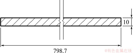
Fig. 1 Cross-sectional shape and dimensions of extrudate (unit: mm)
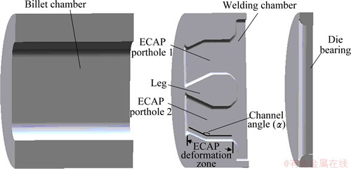
Fig. 2 Basic design of P-ECAP die (a half model)
2 FEM model of P-ECAP extrusion
2.1 Design of P-ECAP dies with different channels angles
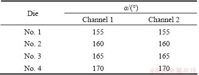
In this work, we firstly developed geometric models of the container, workpiece and other extrusion tooling based on SOLIDWORKS software. Figure 1 shows the dimensions and cross-section of the sheet-metal profile used in the present study. According to the P-ECAP die technique character and workpiece geometrical character of extrusion to manufacture the aluminium sheet-metal, one half of the geometric model of P-ECAP die is shown in Fig. 2. The sheet-metal is a general industrial profile with large flakiness ratio, thus presenting quite a challenge to the die designer and extrusion process engineer because it exerts great loads on the die bearing, restricts extrusion speed and homogeneous deformation needs to be avoided [18,19]. To assist balancing metal flow through the die bearing with very large width (798.7 mm), double channels with angle (porthole 1 and porthole 2 in Fig. 2) were assigned to the die orifice. P-ECAP can effectively improve strength of metallic alloy by producing ultrafine grained microstructure. These two channels are symmetrically distributed in extrusion die. P-ECAP die was conducted using solid die made of H13 with an internal angle of �� (Table 1) between the sideways and axial channels and round off with a radius of curvature of 150 mm. Die bearing with a greater depth (20 mm) in combination with a smoothing angle (D=10 mm) in welding chamber was intended to help the metal flow out the die bearing. To evaluate the effect of channel angle on metal flow, temperature and extrusion load, four P-ECAP dies with channel angle are shown in Table 1 and Fig. 2.
Table 1 Channel angle (��) of P-ECAP die
2.2 FEM simulation software package
DEFORM�C3D, an FEM-based commercial software package, was used to simulate the extrusion of the 6005A aluminium alloy through the four P-ECAP dies with different channel angles and different ram speeds. The software adopts implicit FEM to calculate the rigid-visco-plastic deformation behaviour of the workpiece with thermal effects incorporated, which is especially suitable for the simulation of hot extrusion in the present study.
2.3 Material character and thermal transfer
P-ECAP die, bearing die, stem and container were assumed to be rigid and made of the H13 tool steel with their physical properties given in Table 2. In order to determine the flow stress data of the 6005A aluminium alloy at various strain rates and temperatures for the FE analysis, the hot compression test was performed on a Gleeble-1500 machine, using d10 mm��15 mm compression specimens. To prevent oxidation and obtain a lubricant effect in hot processing, N2 and graphite powder were used. The flow stress data of the 6005A alloy were used as the input material data for the FEM simulations. The physical properties of 6005A aluminium alloy are shown in Table 2. P-ECAP die, bearing die, stem and container, their thermal interactions with the workpiece in the form of conduction were incorporated in the FEM simulations, and so was the thermal transfer within the workpiece, container, die and stem. The boundary conditions for the heat transfer between the objects and the ambient atmosphere took both convection and radiation into account. The heat emissivity and transfer coefficients specified are given in Table 2.
2.4 Friction mechanisms
In hot extrusion process, friction among the die and workpiece, container and workpiece has influence on the extrudate temperature and quality of product, extrusion load and metal flow at the die bearing exit. Because of high temperature and tremendous load in container and die, the exact friction mechanisms involved in the process have not been thoroughly mathematically expressed. It has been acknowledged as the most uncertain parameter in the FEM simulation of aluminum extrusion. In the present study, the friction model was assumed to represent the friction between the workpiece and container and between the workpiece and die:
fs=��k (1)
where fs is the frictional stress; �� is the friction factor; k is the shear yield stress of the deforming workpiece.
A friction factor of 0.40-0.50 was assumed at the interface between the die and workpiece, representing the sliding contact, and 0.75-0.85 between the container and workpiece, representing the nearly sticking contact, as commonly observed in aluminium extrusion practice and confirmed by FLITTA and SHEPPARD [20].
2.5 Mesh generation and optimization
Four-node tetrahedron elements were generated for FEM in this work. Self-adaptive meshing of the workpiece was assumed. To give overall consideration about calculation accuracy and calculation speed, the regions of the workpiece with large deformation and extrudate had finer mesh, while other regions had coarser mesh (Fig. 3). The meshes near the die bearing were finer than those in the other regions of the die. Global remeshing method is active in FEM with 1.05326��107. Figure 4 illustrates the meshed stem, container, assembling die and workpiece (quarter model).
Table 2 Heat transfer coefficients and physical properties of workpiece and extrusion tooling [10]
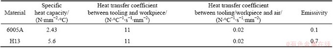
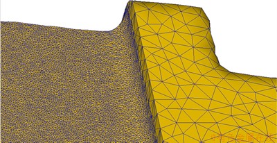
Fig. 3 Finer meshes of regions of workpiece with large deformation
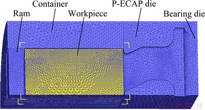
Fig. 4 FEM meshes of ram, workpiece and other extrusion tolling (a quarter of model)
FEM simulations were performed with HUAWEI Tecal T8223 processor workstation. The number of initial elements of the workpiece was 41000. The number of elements of the workpiece increase to 380000, when the extrudate emerged from the die bearing outlet about 250 mm. It was because the regions of the workpiece with large deformation and extrudate had a finer mesh, while other regions had a coarser mesh. With the advanced computing hardware, the simulation of the extrusion process to manufacture a sheet-metal requires frequent remeshing, generating a huge amount of data and taking a very long time. As the main research of the case was to evaluate the effects of ram speed and angle of die channel on peak extrusion load, metal flow and extrudate temperature, the FEM simulations were limited to the transient state of the extrusion process up to the steady state of extrusion load.
2.6 Extrusion process condition
The metal flow, extrusion load and temperature field are affected by parameters such as the initial
temperature of workpiece, the extrusion speed, the extrusion ratio and the workpiece diameter. The P-ECAP die structural system was performed using a square die with a flat similar elliptical cross-section container. Geometric models of initial workpiece or internal diameter of container are shown in Fig. 5. There is a 10 mm gap between workpiece and container after being assembled. For FEM simulations, the bearing length was 20 mm, workpiece temperature was 450 ��C; and for the die and other extrusion tools temperature was selected as 400 ��C for the same extrusion ratio of 16.47. The process variables used in the analysis are shown in Table 3.

Fig. 5 Geometric models of initial workpiece (unit: mm)
3 Reliability analysis of P-ECAP FEM model
To ensure the reliability of FEM simulations model of P-ECAP dies (Fig. 4), round angle was set up to deformation area of P-ECAP die for closing practical situation. In the FEM simulations, the stress-strain of 6005A aluminium alloy material in the temperature range of 300-500 ��C was tested by Gleeble-1500 machine. The machine was used to test stress-strain of metal materials and its accuracy was proven by previous research. The exact process parameters and physical parameters used in the FEM simulations are given in Table 2 and Table 3. All of process parameters such as temperature for aluminium alloy material were proven by previous research [1,16]. All of physical parameters such as emissivity of the material were indicated by material manual.
4 Results and discussion
4.1 Extrudate shape and accuracy of dimension
The effect of flow inhomogeneity on the first extrusion stage is clearly shown in Fig. 6. There is a convex center in the shape of the extrudate front end.
Tablet 3 Process parameters and workpiece dimensions used in FEM simulation and experiments

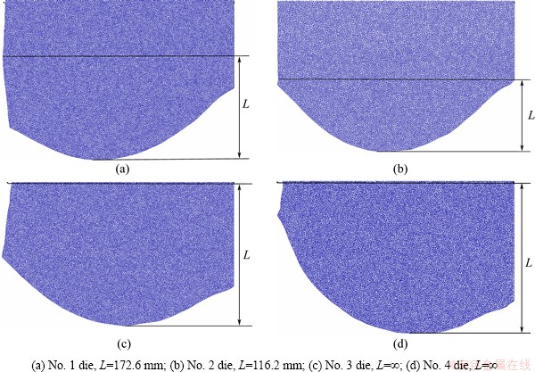
Fig. 6 Dimension of extrudate scrapped part after exiting from EPCAP die with different channel angles at extrusion speed of 3 mm/s(a quarter of model)
From FEM results, it is clear that the metal in the middle of the profile still flowed faster than that at the profile edge, although the rounding in welding chamber was assigned. Figure 6 presents a comparison between the extrudate front ends emerging from the four P-ECAP dies with different channel angles at an extrusion speed of 3 mm/s. It is clear that ��L-value�� in Fig. 6(b) denotes the minimum dimension of the extrudate scrapped part through No. 2 die with a channels angle of 160��. There are some gaps on extrudate through Nos. 3 and 4 die with a channel angle of 165�� or 170��. Serrated appearance to extrudate edge is because of the die with irrationality die construction and the extrudate shrink when it exits from the die. This means that the No. 2 die with a channels angle of 160�� contributes to a good product quality and great dimensional accuracy.
4.2 Distribution of velocity, strain effective
Figure 7 illustrates the distribution of velocity at each extrusion stage. The velocity on the surface is lower than the internal part because of friction between workpiece and die. In outside channels behind channels corner, the metal velocity is greater than that inside. The velocity fields of the material are different, due to the difference in the extrusion ratio at each stage. The distributions of velocity are approximately homogeneous on extrudate front ends. The angle of channels in die structures, as directions of the alloy flow, due to the appropriate angle value of 160��, is believed to be the reason for the observed behavior in Fig. 6(b).
Figure 8 shows the distribution of the effective strain on the cross-section of the extrudate through No. 2 die. The effective strain in the center of product is greater than that in boundary region in product. The non-uniform metal flow led to non-homogeneous strains inside the extrudate. The discrepancy of effective strain between center and boundary region of product is about 2.15. The product cracking phenomenon mostly occurs when the strain is stratification or non-homogeneous [21]. The depth of welding chamber in die structure is the most important parameter which influences the product quality deeply. After lengthening the depth of welding chamber from 80 mm to 120 mm, the effective strain (Fig. 8(b)) on the cross section of the extrudate is more homogeneous than that on longitudinal section.
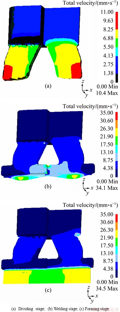
Fig. 7 Distribution of velocity at each stage at initial workpiece temperature of 450 ��C, channels angle of 160�� and extrusion speed of 3 mm/s (3/4 of model)
4.3 Temperature distributions and the maximum temperature of workpiece
Figure 9 shows the distribution of temperature at each stage of extrusion process. In Fig. 9, as the ram proceeds, the heat generated by plastic deformation and friction at the interface between the workpiece and the die causes gradual increase in the workpiece temperature [14-16]. In this particular FEM simulation of P-ECAP extrusion through die No. 2 with channels angle of 160�� and the ram speed of 3 mm/s, it can be seen that from Fig. 9(a), at the dividing stage, the temperature of the workpiece was lower than the initial workpiece temperature except the center area. This is because initial temperatures of die and container are lower compared with the workpiece. Heat exchange occurs when workpiece contacts with container and die. When the metal flows through the channels corner, the added deformation process begins, and as a result, local temperature rise caused by plastic deformation is obvious. On the other hand, the direction of metal flow turns to z-axis from outspread direction. It would be beneficial to metal welding in chamber. When the metal flows in the welding chamber, the local temperatures are approaching to the initial workpiece temperature. This thermal phenomenon is because at the beginning of extrusion, the hotter workpiece contacts the colder extrusion die and thermal radiation takes place and the heat production caused by deformation is counteracted. When the metal flows into the die bearing, the work piece temperature increases rapidly from 438-450 ��C to 450-463 ��C (Fig. 9(c)) as a result of large deformation.
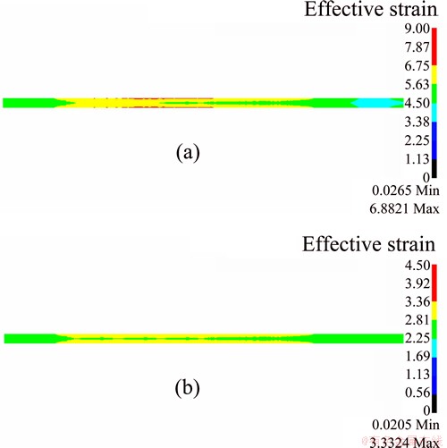
Fig. 8 Effective strain distribution on cross section of extrudate through No. 2 die (a half of model) (a) and welding chamber of No. 2 die optimized (b)
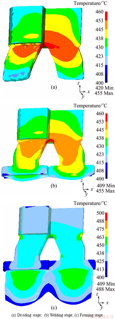
Fig. 9 Distribution of temperature at each stage with initial workpiece temperature of 450 ��C, channels angle of 160�� and extrusion speed of 3 mm/s (3/4 of model)
The maximum temperature of the workpiece is critical to the surface quality of the extrudate, its microstructure and also to its strength. The results of previous studies [18,19] on temperature evolution during conventional extrusion of 7075 aluminium alloy showed that the maximum workpiece temperatures during extrusion at various ram speeds were all a linear function of logarithmic ram displacement. In addition, the maximum workpiece temperatures at different ram displacements varied linearly with logarithmic ram speed. Figure 10 shows the variation of the maximum workpiece temperature with ram displacement at different ram speeds, where the five ram speeds are compared. When the ram speed is 1 mm/s, it shows the initial decrease of the maximum temperature during the filling of the channels and welding chamber. This is because thermogenesis by deformation and friction is less than heat transferring from workpiece to die. When the ram speed is 1, 3, 5, 7 or 9 mm/s, the durative increase of the maximum temperature during the filling of the channels and welding chamber appears. This is because thermogenesis by deformation and friction is greater than heat transferring from workpiece to die. The rapid temperature rise occurs in filling die bearing, and as a combined result of friction and severe deformation, the magnitude of this temperature rise is in relation to ram speed. It can be seen that the ram speed has a profound effect on the maximum workpiece temperature. An increase in the ram speed from 1 to 9 mm/s leads to the maximum temperature further increasing from 465 to 535 ��C. It is about 70 ��C distinction between 1 and 9 mm/s of ram speed. When the ram speed is 7 mm/s or 9 mm/s, the maximum workpiece temperature is close to the incipient melting point of the 6005A aluminium alloy, deciding that the extruded profile will be scrapped or have bad surface quality. So, 3-5 mm/s should be the optimization ram speed.
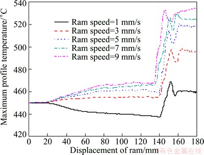
Fig. 10 Maximum workpiece temperature as function of ram displacement during conventional extrusion with ram speed in initial workpiece temperature of 450 ��C and channels angle of 160��
4.4 Distributions of maximum principal stress, effective stress and extrusion load
In the extrusion of bullet train aluminium alloys, the sheet-metal surface quality depends on the maximum extrudate temperature, in addition to stress state at the channels, welding chamber and die bearing. But the effect of stress state at the die bearing is remarkable. If the tensile stress exceeds the fracture strength of the workpiece material, speed cracking may be encountered. It has been found that the speed cracking is actually caused by a combination of strain and tensile stress that exceeds a fracture criterion [22,23]. Figure 11(a) shows the distribution of the maximum principal stress on the longitudinal section of the workpiece during P-ECAP extrusion with the ram speed of 3 mm/s and the No. 2 die. It can be seen that, from the ram to the die bearing, the maximum principal stresses in the whole workpiece are compressive. In the corner of ECAP deformation zone, the maximum principal stresses have ascending trend. In the solder seam and the side of die bearing of extrudate, the maximum principal stresses are tensile stress. The maximum tensile stress is 22.4 MPa. It cannot influence the quality of sheet-metal surface or not exceed the fracture strength of the alloy. Figure 11(b) shows the distributions of the effective stress on the longitudinal section of the workpiece with the same situation in Fig. 11(a). The maximum principal stress and effective stress are similar, especially in ECAP deformation zone. This stress state could minimize microstructural damage and evaluate some structural defects introduced during die design phase.
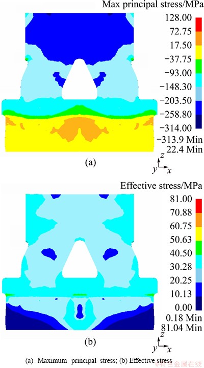
Fig. 11 Distributions of stress during isothermal extrusion with extrusion speed of 3 mm/s and channels angle of 160�� on longitudinal section of workpiece
Figure 12 compares the extrusion loads during extrusion at the ram speed of 1, 3, 5, 7 and 9 mm/s with the initial workpiece temperature 450 ��C and channels angle 160��. To all of these extrusion modes, the total extrusion load reaches a peak at the middle of the process, about ram displacement of 170 mm. At the peak, extrusion loads reach 8-12.5 MN. It should save labour compared with the other manufacture method [19,21]. Every ascent stage goes with a deformation. The result is similar to previously study [10]. Before the peak, there are four ascent stages corresponding to four extrusion stages. The first ascent stage is because of alloy diffluence, severe shearing deformation occurring with the alloy flowing in channels. The second ascent stage is because of equal channel angular pressing (ECAP). Extrusion load has a few ascent as a result of alloy through the channel angle. This means that ECAP process has been successfully used to predeformation in producing the sheet-metal. There are a lot of pre-treatment technologies, but the predeformation is used to an independency process. The third ascent stage is because of the alloy filling in welding chamber. The last ascent stage of forces appears because the metal flows towards the die orifice. Then there is an extrusion load peak. Figure 12 also shows that the breakthrough load is affected by the ram speed. Every extrusion load curve is approximately parallel to each other. As ram speed is increased from 1 mm/s to 9 mm/s, the peak extrusion load is increased by about 49%. It is generally understood that the load peak is related to the generation of a high density of dislocation before the steady state is established [16]. The continuous load decrease after the peak is a combined result of the gradually diminishing friction between the workpiece and container and the temperature rise in the remaining workpiece. But the extrusion load reduction is slow and limited.
The comparison between simulated and experimental values of fuzzy prediction systems for extrusion load is shown in Fig. 13, The process parameters of simulation and experiment are accordant with the modified data of the chamber depth of 12 mm, channels angle of 160�� and ram speed of 3 mm/s. The dimensions of die and billet are 0.1 times those in the foregoing FE study. The tendencies are approximative for the simulation and the experiment; the experimental value is a little more than the simulated value, especially the peak value. The ascent stages of four extrusion load values calculated are inconspicuous. The results indicate that the proposed constitutive model is reliable.
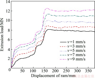
Fig. 12 Load evolutions during extrusion through P-ECAP dies at initial workpiece temperature 450 ��C and channels angle 160��
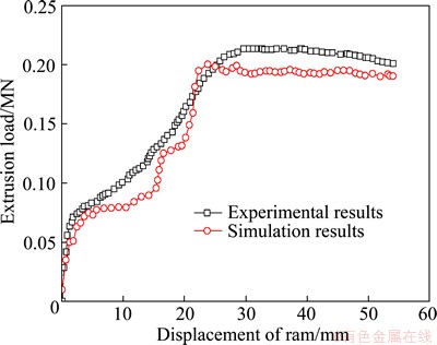
Fig. 13 Comparison between simulated and experimental values for extrusion loads
5 Conclusions
1) Ram speed profiles for P-ECAP extrusion were predetermined by means of FEM simulation, based on the predicted maximum workpiece temperature, temperature evolution, maximum principal stress, effective stress, and extrusion load during extrusion at constant ram speeds and die structure. 6005A Al alloys plate for the high-speed train could be obtained by P-ECAP extrusion. Comparison between simulated and experimental values for extrusion loads indicated that the proposed constitutive model was reliable.
2) The effect of flow inhomogeneity on the first extrusion stage was clearly presented. There was a convex center in the front end shape of the extrudate. Extrudate front end through the die with a channel angle of 160�� contributed to a good product quality and dimensional accuracy. The effective strain on the cross-section of the extrudate was homogeneous when the depth of welding chamber was 120 mm.
3) With the predetermined ram speed and extrusion load profiles, a reasonable and stable maximum workpiece temperature could be maintained with a ram speed of 3-5 mm/s. The effect of ram speed on extrusion load was remarkable. With the increase in the ram speed from 1 to 9 mm/s, the peak extrusion load was increased by about 49%. The curves obtained for different extrusion loads were approximately parallel to each other.
4) The effect of severe distortion on the ascending stages of the extrusion loads occurred in the particular deformation zone. When the alloy was in ECAP stage, extrusion loads displayed some ascent. Predeformation of the billet occurred before the alloy arrived at the welding chamber.
References
[1] MOHAMMAD R R, MOHAMMAD R T, FAKHREDDIN A. Production of nano-grained structure in 6061 aluminum alloy strip by accumulative roll bonding [J]. Materials Science and Engineering A, 2011, 529: 442-446.
[2] MOHAMMAD R R, MOHAMMAD R T, FAKHREDDIN A. Effects of ARB and ageing processes on mechanical properties and microstructure of 6061 aluminum alloy [J]. Journal of Materials Processing Technology, 2011, 211: 1184-1190.
[3] VALIEV R Z, ISLAMGALIEV R K, ALEXANDROV I V. Bulk nanostructured materials from severe plastic deformation [J]. Progress Materials Science, 2000, 45: 103-189.
[4] CHENG X, STEVEN S, PATRICK B B, TERENCE G L. Principles of ECAP��Conform as a continuous process for achieving grain refinement: Application to an aluminum alloy [J]. Acta Materialia, 2010, 58: 1379-1386.
[5] RUSLAN Z V, YURI E, ZENJI H, TERENCE G L, MICHAEL J Z, YUNTIAN T Z. Producing bulk ultrafine-grained materials by severe plastic deformation [J]. Journal of the Minerals, Metals and Materials Society, 2006, 58: 33-39.
[6] RUSLAN Z V, TERENCE G L. Principles of equal-channel angular pressing as a processing tool for grain refinement [J]. Progress Materials Science, 2006, 51: 881-981.
[7] SEGAL V M. Equal channel angular extrusion: From macromechanics to structure formation [J]. Materials Science and Engineering A, 1999, 271: 322-333.
[8] SEGAL V M. Materials processing by simple shear [J]. Materials Science and Engineering A, 1995, 197: 157-164.
[9] SEGAL V M. Equal channel angular extrusion of flat products [J]. Materials Science and Engineering A, 2008, 476: 178-185.
[10] FANG G, ZHOU J, DUSZCZYK J. Extrusion of 7075 aluminium alloy through double-pocket dies to manufacture a complex profile [J]. Journal of Materials Processing Technology, 2009, 209: 3050-3059.
[11] ZHANG Z J, SON I H, IM Y T, PARK J K. Finite element analysis of plastic deformation of CP-Ti by multi-pass equal channel angular extrusion at medium hot-working temperature [J]. Materials Science and Engineering A, 2007, 447: 134-141.
[12] PURCEK G, O SARAY, KUL O, KARAMAN I, YAPICI G G, HAOUAOUI M, MAIER H J. Mechanical and wear properties of ultrafine-grained pure Ti produced by multi-pass equal-channel angular extrusion [J]. Materials Science and Engineering A, 2009, 517: 97-104.
[13] YANG He, SHI Lei, GUO Liang-gang, ZHANG Bao-jun. P-ECAP broadening extrusion to manufacture a plate: China, 201210076203.X [P]. 2012-07-25. (in Chinese)
[14] LI H, LI S Y, ZHANG D H. On the selection of outlet channel length and billet length in equal channel angular extrusion [J]. Computational Materials Science, 2010, 49: 293-298.
[15] THAM Y W, FU M W, HNG H H, YONG M S, LIM K B. Bulk nanostructured processing of aluminum alloy [J]. Journal of Materials Processing Technology, 2007, 192-193: 575-581.
[16] KIM J K, KIM H K, PARK J W, KIM W J. Large enhancement in mechanical properties of the 6061 Al alloys after a single pressing by ECAP [J]. Scripta Materialia, 2005, 53: 1207-1211.
[17] YOUNG G J, HYUN M B, YONGTAEK I, BYUNG C J. Continuous ECAP process design for manufacturing a microstructure-refined bolt [J]. Materials Science and Engineering A, 2011, 530: 462-468.
[18] LI L, ZHOU J, DUSZCZYK J. Prediction of temperature evolution during the extrusion of 7075 aluminium alloy at various ram speeds by means of 3D FEM simulation [J]. Journal of Materials Processing Technology, 2004, 145: 360-370.
[19] CASTLE A F, SHEPPARD T. Pressure required to initiate extrusion in some aluminium alloys [J]. Metals Technology, 1976, 3: 465-475.
[20] FLITTA I, SHEPPARD T. Nature of friction in extrusion process and its effect on material flow [J]. Materials Science and Technology, 2003, 19: 837-846.
[21] HE Y F, XIE S S, CHENG L, HUANG G J, FU Y. FEM simulation of aluminum extrusion process in porthole die with pockets [J]. Transactions of Nonferrous Metals Society of China, 2010, 20: 1067-1071.
[22] ZHOU J, LI L, DUSZCZYK J. Computer simulated and experimentally verified isothermal extrusion of 7075 aluminium through continuous ram speed variation [J]. Journal of Materials Processing Technology, 2004, 146: 203-212.
[23] HSIANG S H, LIN Y W. Application of fuzzy theory to predict deformation behaviors of magnesium alloy sheets under hot extrusion [J]. Journal of Materials Processing Technology, 2008, 201: 138-144.
С���ϵ�ͨ��ת�Ƿ����¼�����ѹ�������Ͻ��
ʯ ��1���� ��1��������1���� ��1���� ��2
1. ������ҵ��ѧ ����ѧԺ ���̼��������ص�ʵ���ң����� 710072��
2. �й����ͻ�е�о�Ժ����˾������ 710032
ժ Ҫ��Ϊ�˽�ϵ�ͨ��ת�Ǻͷ�����ѹ����������ģ��о���һ�ֵ�ͨ��ת�Ƿ���(P-ECAP)��ѹ�¼�����ͨ������Ԫ�����о������ڸ����г���6005A���Ͻ��ĵļ�ѹ���ڴ�ͳ����ģ�ߵķ���ͨ��������˵�ͨ��ת�ǹ��ա�Ԥ���˲�ͬͨ��ת�Ƕ�P-ECAP���ռ�����ĵķ��ϳ��ȱ仯��Ӱ�죻�о���ͨ��ת�Ǻͼ�ѹ�ٶȶ�����¶Ⱥ�������������Ӱ�졣��������������ͨ��ת��Ϊ160��ʱ������õijߴ羫�ȣ����ҷ��ϵijߴ�Ҳ��С����Ϊ�����ļ�ѹ�ٶ�Ϊ3~5 mm/s�����⣬����ѹ�ٶȴ�1 mm/s���ӵ�9 mm/s ʱ����ѹ���ķ�ֵ������49%������������¶�������70 ��C����ͨ���ڵ�ת�DZ���������ЧӦ�����������ƣ�������ĵĺ�������ģ�߱�Ե�����Ӧ��Ϊ��Ӧ����
�ؼ��ʣ�С���ϣ�����ģ�ߣ���ͨ��ת�ǣ���ѹ
(Edited by Hua YANG)
Foundation item: Project (B08040) supported by the Program of Introducing Talents of Discipline to Universities (111 Project), China; Project (2009ZX04005-031-11) supported by the National Science and Technology Special Program, China
Corresponding author: He YANG; Tel: +86-29-88460212; E-mail: yanghe@nwpu.edu.cn
DOI: 10.1016/S1003-6326(14)63221-0
Abstract: To manufacture plate by the combination of equal channel angular processing (ECAP) and porthole die extrusion techniques, a novel technique, namely portholes-equal channel angular processing (P-ECAP), was studied. Extrusion of AL6005A plate used for the bullet train plate was investigated by finite element method. The relevant porthole dies involving ECAP technique in channels were designed. Dimensional changes in the scrap part of the extrudate obtained after extrusion from the P-ECAP die, with different channel angles, were predicted. Effects of the channel angle and extrusion speed on the maximum temperature of the workpiece and other field variables were evaluated. At the channel angle of 160�� of P-ECAP dies, the extrudate exhibited the optimal performance and the least amount of extrudate scrap was obtained. The optimal extrusion speed was 3-5 mm/s. Moreover, with the increase in ram speed from 1 to 9 mm/s, the peak extrusion load increased by about 49% and the maximum temperature was increased by about 70 ��C. The effective strain exhibited ascending trend in the corner of the ECAP deformation zone. In the solder seam and the side of die bearing of extrudate, the maximum principal stresses were tensile stress.
