

Effects of coil length on tube compression in electromagnetic forming
YU Hai-ping(�ں�ƽ), LI Chun-feng(���)
School of Materials Science and Engineering, Harbin Institute of Technology, Harbin 150001, China
Received 15 July 2007; accepted 10 September 2007
Abstract:
The effects of the length of solenoid coil on tube compression in electromagnetic forming were investigated either by theory analysis or through sequential coupling numerical simulation. The details of the electromagnetic and the mechanical models in the simulation were described. The results show that the amplitude of coil current waveform and the current frequency decrease with the increase of the coil length. And the peak value of magnetic pressure is inversely proportional to the coil length. The distribution of the magnetic force acting on the tube is inhomogeneous while the tube is longer than the coil. The shortened coil length causes the increases of the maximum deformation and energy efficiency. The numerically calculated result and the experimental one of the final tube profile are in good agreement.
Key words:
coil length; tube compression; sequential coupling simulation; inductance; electromagnetic forming;
1 Introduction
Considering the necessity of energy saving, growing environmental pollution, and the resulting ever stricter legal regulations, the light-mass and high strength materials, such as aluminum alloys, have been widely used lately in the aerospace and automotive industries[1-4]. Whilst the electromagnetic forming(EMF) technology has peculiar advantages in forming, joining and assembly of these metal materials because of improved formability, improved strain distribution, reduction in wrinkling, active control of springback, minimized distortions at local features, local coining and simple die[5-8].
The circuit of the EMF consists of an EMF machine, part, transmission lines and buses, field shaper and primary coil. The coil is the main tool, whose structural and electrical parameters play an important role in the space distribution of magnetic field, and the peak value and width of the magnetic pressure pulse acting on the part[9-10]. So the coil design and structural optimization is one of the key problems needed urgently for the development and application of EMF that relates to electromagnetics, plastic mechanics, dynamics, and so on. Ref.[11] presents some analytic solution of the coil design. However the formulae are complicated and inconvenient to use. In Ref.[12], the effects of various working conditions of electromagnetic tube bulging on the tube profile and forming efficiency were experimentally investigated. The fewer the turns of the coil and the smaller the capacity of the capacitor bank, the higher the forming efficiency. A new kind of driving coil for electromagnetic riveting was designed with good durability and long life in Ref.[13]. And the elliptical coil is suitable for rectangular part in comparison with the circular one[14].
In summary, few documents and researches have been found on the relationship between the coil length and tube compression. In this work, the effects of coil length on the waveform of coil current pulse, the peak value of equivalent magnetic pressure, the magnetic force, the deformation characteristics of the tube and the energy efficiency during electromagnetic tube compression are investigated either analytically or through the sequential coupling numerical simulation. The results contribute to the more systematic analysis of the EMF process, offering valuable information about the process principles and practical realization as well as the coil design.
2 Experimental
The coil is coaxial and concentric with the tube in this electromagnetic tube compression system. The dimensions and shape of the electromagnetic tube compression system are shown in Fig.1. The EMF machine used in the experiments is EMF-30 (total capacitance 70.2 ��F/kV) at Harbin Institute of Techno- logy, China.
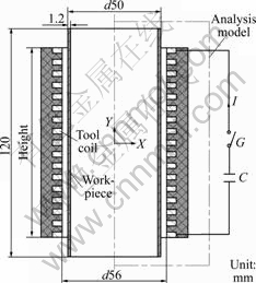
Fig.1 System model for electromagnetic tube compression
A pulse of current through the coil is the load in EMF, which is easily measured by experiment. The first period of the current pulse is considered to be responsible for the tube compression. In electromagnetic forming, the current is proximately expressed by
![]() (1)
(1)
where U=1.8 kV, is the initial discharge voltage; C=702 ��F, is the total capacitance of capacitor bank; L is the equivalent inductance of the tube compression system; �� is the damping exponent and �� is the angular frequency. The values of L, �� and �� for various coils are listed in Table 1, which present the geometry parameters of coils.
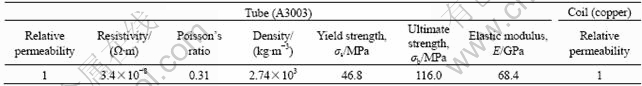
The main properties of the contributing materials in this experiment are included in Table 2. Aluminum alloy (A3003) tubes were prepared to carry out the tube compression tests. The constitutive behavior of the tube material, obtained at the Instron-1186 electronic tensile testing machine, is expressed as
![]() (2)
(2)
where �� is plastic strain.
The radial displacement of the deformed tube was measured to estimate the effect of coil length on the moderate deformation before buckling. The geometry of FEA (Finite Element Analysis) models in the following analysis was obtained from the setup. The experimental values of tube compression with variable coils were given and could be used to validate the simulation by the sequential coupling simulation.
3 Finite element analysisIn the sequential coupling numerical simulation, the electromagnetic and mechanical models are established respectively. First, the transient magnetic forces are calculated from the electromagnetic model, which are then used as the input load to simulate the tube��s high velocity deformation from the mechanical model in each time step. Whereafter, the transient magnetic forces are calculated again based on the tube��s updated geometry in the next time step. Therefore, the sequential coupling that is more accurate than the loose coupling and the half coupling methods[15-17] is realized between the both models.
Only half view of the electromagnetic model, where the air region around the tube compression system must be included, is considered in this analysis because of symmetry. The model consists of far field air region, tube, coil, near field air region and one special air region around the forming tube. The geometry of the electromagnetic model is updated through morphing magnetic force acting on the tube at the peak current with the coils included in Table 1. The distribution of the magnetic force acting on the tube is inhomogeneous while the tube length is longer than that of the coil. The shorter coil produces higher magnetic force and shorter region, where the force acts on it.
Table 1 Parameters of coil for tube compression
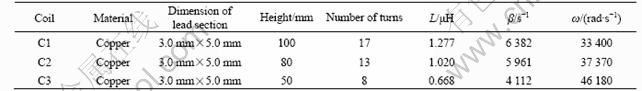
Table 2 Material parameters of system
magnetic force acting on the tube at the peak current with the coils included in Table 1. The distribution of the magnetic force acting on the tube is inhomogeneous while the tube length is longer than that of the coil. The shorter coil produces higher magnetic force and shorter region, where the force acts on it.
The numerical analysis for the electromagnetic tube compression has been performed by using the multiphyiscs FEM software ANSYS. The finite element meshes for the electromagnetic and mechanical models with the coil C1 are shown in Fig.2. The other regions are meshed through mapped meshing method with Plane 13 quadrilateral element besides the near field air region, which is irregular and meshed through free meshing method with Plane 13 triangular element. In total, 4 924 triangular and 1 880 quadrilateral elements are used in the electromagnetic model, which are compatible with 246 elements (Plane 182 element) used in the mechanical model. The mesh division in the coil and the tube regions are same in both analyses in order to transfer the nodal magnetic forces and update the geometry of the electromagnetic model across the two models. Finer meshes are used to describe the regions of the coil and the tube for taking into account of the skin effect of the tube and obtaining the reliable results.
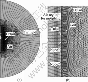
Fig.2 Meshes for EM and mechanical analyses: (a) FE model arrangement presented in Fig.1; (b) Detail including coil and tube
The load of the electromagnetic model is the current pulse through the coil. In the mechanical model, the quasi-static data of the tube material properties are scaled, to adapt the high strain-rate conditions of the process, by means of the Cowper-Symonds constitutive model[15]:
![]() (3)
(3)
where ��y is the quasi-static flow stress, ![]() is the strain rate, P=6 500 s-1 and m=0.25 are specific parameters for aluminum.
is the strain rate, P=6 500 s-1 and m=0.25 are specific parameters for aluminum.
The mechanical model is only related to the tube and coil. And only moderate deformations are usually desirable because of the limitation imposed by the plastic buckling in the electromagnetic tube compression. So the deformation analysis does not take into account of the buckling. The inertial effects are considered since the stress is transient.
The load and boundary conditions are both applied to nodes and the detailed presentation of the boundary conditions for the electromagnetic model is given in Ref.[16]. The total simulation time is 200 ��s and the time step is 5 ��s.
4 Analysis and discussionThe discharge voltage and energy are kept constant in the simulation and experiments, and the values are 1.8 kV and 1.137 kJ, respectively.
4.1 Coil current waveformWhen the coil is coaxial with the tube, the equivalent inductance(L) of the discharge circuit can be expressed as Eqn.(4) that consists of the inherent inductance(Li) of the circuit and the forming inductance (coil and tube)[18]:
L=Li+Lc(1-a2/c2) (4)
where a is the tube middle radius (m), c is the coil inner radius (m), Li is the inherent inductance of circuit (H), Lc is the coil inductance (H)[13].
Lc=�˦�0��c2T2l (5)
where ��0 is the vacuum permeability (H/m), �� is the Nagaoka coefficient, T is the turn number on the unit length of coil, l is the coil length (m).
From Eqn.(5), L depends mainly on the coil inductance and the relative dimension between the coil and the tube for Li is much less than the forming inductance. Therefore the increased length and radius of coil cause the increase of volume of tube and the equivalent inductance of the circuit. However, L is related to the coil length and the turn number on unit length of the coil because the radius of the solenoid coil is usually defined by both the outer radius of the tube and the enough insulation in electromagnetic tube compression. In this work, L is determined by the coil length for the defined dimensions of the coil lead (3.0 mm��5.0 mm).
Fig.3 shows the coil length dependence of the primary current waveform. The amplitude of the current pulse reduces and the period of it prolongs with the increase of the coil length.

Fig.3 Effect of coil length on current
4.2 Nominal peak magnetic pressureIn electromagnetic forming, the tube deformation is governed by the circuit parameters after discharge of capacitors in EMF machine. The power equilibrium during the EMF process can be described as[18]
![]() (6)
(6)
where I is the coil current (A), Q is the charge in capacitor bank (C), ![]() is the mechanical power (W).
is the mechanical power (W).
The voltage equilibrium is expressed by
![]() (7)
(7)
It can be derived from Eqns.(1) and (4)-(7):
![]() (8)
(8)
where p0 is the nominal peak value of magnetic pressure (Pa) that can be expressed by
![]() (9)
(9)
It can be concluded from Eqn.(9) that the peak value of the magnetic pressure pulse depends on the length and the inner radius of the coil besides the discharge energy. Coil length is inversely proportional to the peak value with the discharge energy and the inner radius of the coil keeping constant. And the shorter coil causes the greater peak value and the smaller region, where the magnetic pressure acts on it.
4.3 Simulation of radial magnetic forceFig.4 shows the distribution of radial nodal magnetic force acting on the tube at the peak current with the coils included in Table 1. The distribution of the magnetic force acting on the tube is inhomogeneous while the tube length is longer than that of the coil. The shorter coil produces higher magnetic force and shorter region, where the force acts on it.

Fig.4 Magnetic forces of peak current with varied coil
The variations of the magnetic forces acting at the center node of the tube��s outer surface (Node 1) and at the node opposite to the coil end (Node 2) as a function of time are shown in Fig.5. With the decrease of the coil length, the amplitudes of the forces acting at the both nodes increase and their periods decrease; and the tube length outside the coil increases, which strongly restricts the magnetic field, so the magnetic force at Node 2 with C3 is damped slowly. 4.4 Simulation of tube compressionFig.6 shows the final tube profile with variable coils included in Table 1. The tube radius increases rapidly and the length of the uniform deformation region decreases with the decrease of the coil length. It can be seen that the numerically calculated result and the experimental one are in good agreement. And the relation between the peak value of magnetic pressure and the coil length can also be validated.
Fig.7 shows the variations of the tube profile as a function of time with different coil in simulation. The final tube profile is similar to the distribution of magnetic force described in Fig.4, which indicates some pertinence between them. As shown in Fig.7, the changing gradient of displacement at tube center increases with the decrease of the coil length, which illustrates the maximum forming velocity with C3.
4.5 Plastic strain energy of tubeKeeping the discharge energy constant, the shorter coil can improve the energy efficiency (ratio of the plastic strain energy to the discharge energy) during the EMF process. The result is similar to that presented in Ref.[12], which is relevant to the electromagnetic tube bulging. Fig.8 shows the changes of the plastic strain
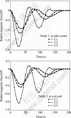
Fig.5 Variations of radial magnetic force with time: (a) Node 1; (b) Node 2

Fig.6 Effect of coil length on displacement

Fig.7 Effect of coil length on radial displacement: (a) C1; (b) C2; (c) C3
energy with time. The plastic strain energy with C1, C2 and C3 are 95.5, 107.5 and 150.1 J, respectively. Therefore, the energy efficiencies increase with the decrease of the coil length and they are 8.40%, 9.45% and 13.22%, respectively.

Fig.8 Effect of coil length on plastic strain energy of tube
5 Conclusions1) The amplitude of coil current waveform and the frequency of the current decrease with the increase of the coil length. And the peak value of magnetic pressure is inversely proportional to coil length.
2) The distribution of the magnetic force acting on tube is inhomogeneous while tube length is larger than coil length. And the tube length outside the coil increases with the decrease of the coil length, which strongly restricts the penetration of magnetic field, so the corresponding magnetic force opposite to coil C3 end is damped slowly.
3) The shortened coil length causes the increase of the maximum deformation, forming velocity and energy efficiency. The numerically calculated result and the experimental one of the final tube profile are in good agreement.
References[1] UHLMANN E, JURGASCH D. New impulses in the forming of magnesium sheet metals [C]// KLEINER M. Proceedings of 1st international conference on high speed forming. Dortmund: 2004: 229-241.
[2] DAEHN G S, VOHNOUT V J, DATTA S. Hyperplastic forming: Process potential and factors affecting formability [J]. Mat Rew Soc Symp Proc, 2000, 601: 247-252.
[3] RESCH D, BEERWALD C, BROSIUS A, KLEINER M. On the significance of the die design for electromagnetic sheet metal forming [C]// KLEINER M. Proceedings of 1st international conference on high speed forming. Dortmund: 2004: 191-200.
[4] NEUGEBAUER R, LOSCHMANN F, PUTZ M, KOCH T, LAUX G. A production-oriented approach in electromagnetic forming of metal sheets [C]// KLEINER M. Proceedings of 2nd international conference on high speed forming. Dortmund: 2006: 129-139.
[5] SETH M, VOHNOUT V J, DAEHN G S. Formability of steel sheet in high velocity impact [J]. Journal of Materials Proceeding Technology, 2005, 168: 390-400.
[6] DAEHN G S, SHANG J H, VOHNOUT V J. Eelectromagnetically assisted sheet forming: Enabling difficult shapes and materials by controlled energy distribution [C]// TMS (The Minerals, Metals & Materials Society) Proceedings. USA: 2003: 117-128.
[7] KAMAL M. A uniform pressure electromagnetic actuator for forming flat sheets [D]. Ohio: Ohio State University, 2005.
[8] Office of Advanced Automotive Technologies. Automotive lightweighting materials D: Electromagnetic forming of aluminum sheet[EB/OL]. http://www1.eere.energy.gov/vehiclesand fuels/ pdfs/ alm_05/2d_davies.pdf., 2006-11-10
[9] KLEINER M, BEERWALD C, HOMBERG W. Analysis of process parameters and forming mechanisms within electromagnetic forming process [J]. CIRP Annals-Manufacturing Technology, 2005, 54(1): 225-228.
[10] EL-AZAB A, GARNICH M, KAPOOR A. Modeling of the electromagnetic forming of sheet metals: State-of-the-art and future needs [J]. Journal of Materials Processing Technology, 2003, 142: 744-754.
[11] BELEY I V, FERRTIK S M, KHIMENKO L T. Electromagnetic metal forming handbook [M]. ALTYNOVA M M, ed. Ohio: Ohio State University Press, 1996.
[12] ZHANG Hai, MAKOTO M, TOMOKATU A, HIDEO S. Tube bulging by electromagnetic forming using sheet spiral coil [J]. Transactions of the Japan Society of Mechanical Engineers (Part C), 1993, 59(567): 3585-3590. (in Japanese)
[13] SHENG Xi, CAO Zeng-qiang. Design and manufacture of driving coil of electromagnetic forming [J]. Mechanical Science and Technology, 2003(S): 47-48. (in Chinese)
[14] CHU Hong-yan, FEI Ren-yuan, WU Hai-bo, LU Xin. Application research of elliptic working coil used in sheet metal electromagnetic forming [J]. Forging & Stamping Technology, 2002(5): 38-41. (in Chinese)
[15] MAMALIS A G, MANOLAKOS D E, KLADAS A G, KOUMOUTSOS A K. Electromagnetic forming and powder processing: Trends and developments [J]. Appl Mech Rev (ASME), 2004, 57(4): 299-324.
[16] YU H P, LI Z, LI C F. Numerical simulation of coupled fields of electromagnetic forming for tube compression based on FEM [J]. Chinese Journal of Mechanical Engineering, 2006, 42(7): 231-234. (in Chinese)
[17] YU Hai-ping, LI Chun-feng. Finite element analysis of free expansion of aluminum alloy tube under magnetic pressure [J]. Transa Nonferrous Met Soc China, 2005, 15(5): 1040-1044.
[18] AL-HASSANI S T S. The plastic buckling of thin-walled tubes subject to magnetomotive forces [J]. Journal of Mechanical Engineering Science, 1974, 16(2): 59-70.
(Edited by YANG Bing)
Foundation item: Project(50575052) supported by the National Natural Science Foundation of China
Corresponding author: YU Hai-ping; Tel: +86-451-86413970; Fax: 86-451-86418753; E-mail: haipingy@hit.edu.cn
