
J. Cent. South Univ. (2017) 24: 921-928
DOI: 10.1007/s11771-017-3494-9

Thermal analysis of an LED module with a novelly assembled heat pipe heat sink
TANG Yong(����), CHEN Qiu(����), GUAN Wo-huan(���ֻ�),
LI Zong-tao(������), YU Bin-hai(���), YUAN Wei(Ԭΰ)
School of Mechanical and Automotive Engineering, South China University of Technology, Guangzhou 510640, China
 Central South University Press and Springer-Verlag Berlin Heidelberg 2017
Abstract:
This work aims to improve the thermal performance of a light emitting diode (LED) module by employing a novelly assembled heat pipe heat sink. The heat pipe was embedded into the heat sink by a phase change expansion assembly (PCEA) process, which was developed by both finite element (FE) analysis and experiments. Heat transfer performance and optical performance of the LED modules were experimentally investigated and discussed. Compared to the LED module with a traditionally assembled heat pipe heat sink, the LED module employing the PCEA process exhibits about 20% decrease in the thermal resistance from the MCPCB to the heat pipe. The junction temperature is 4% lower and the luminous flux is 2% higher. The improvement in the thermal and optical performance is important to the high power LED applications.
Key words:
light emitting diode (LED); phase change assembly; heat pipe; heat sink; thermal analysis��
1 Introduction
In recent years, light emitting diode (LED) is enjoying exceptional popularity in various lighting applications such as general lighting, LCD backlights, automobile headlamps and architectural decorations. Compared with conventional incandescent lamps or fluorescent lamps, LEDs demonstrate several pronounced advantages such as energy saving, ultra-fast response, long life time and environmentally friendly features [1-3]. Nevertheless, when LEDs are operating, 70%-85% of the input electric energy is converted into heat [4]. If the heat cannot dissipate efficiently, the junction temperature will rise rapidly and problems occur. Narendran��s research revealed that the life of LEDs decrease in an exponential manner with increasing temperature [5]. CHHAJED et al [6] detailedly studied the influence of junction temperature on the optical performance of a trichromatic white-light LED. They found that as the junction temperature increases, the luminous efficacy and the color rendering index (CRI) decrease, the color temperature increases and the chromaticity point shifts towards the blue. Therefore, to compete with and to surpass the performance of traditional lighting, effective thermal management is one of the most significant factors for success.
Researchers have been striving to boost the thermal performance of the LEDs. Active cooling methods such as micro-jet arrays [7], liquid metal cooling [8], forced convection [9] and electro-hydrodynamic approaches [10] have been reported to perform thermal management for the LEDs. These methods have greatly improved the performance and reliability of the LEDs. To meet the explosive market demands, heat pipe heat sink has been also adopted for its excellent thermal conductivity and high reliability. KIM et al [11] introduced a heat pipe to a six-package LED array operating at an air velocity of 7m/s and achieved a 24.3 ��C decrease in the junction temperature. LI et al [12] proposed a loop heat pipe heat sink with parallel condensers for high power integrated LED chips. They further revealed that the loop heat pipe heat sink had a total thermal resistance as low as 0.4 ��C/W at a heating load of 300 W under natural convection. Additionally, other researchers presented flat heat pipe [13] and vapor chamber [14], which also provided creative ideas for thermal management of the LEDs. However, most of the studies mainly focused on the design and the structure optimization of the heat pipe heat sink [15], while the importance of the assembly process between the heat pipe and the heat sink has been rarely reported to the best knowledge of the authors. As for the most commercial heat pipe heat sink, the heat pipe is directly inserted into the groove of the heat sink [16, 17], In such case, insufficient assembly accuracy could induce air gap between the heat pipe and the heat sink, therefore increasing the thermal resistance and deteriorating the thermal-optical performance as well as service life of the LEDs.
2 Phase change expansion assembly process
This paper aims to improve the thermal performance of a LED module by employing a novelly assembled heat pipe heat sink. The heat pipe was embedded into the heat sink by an optimized phase change expansion assembly (PCEA) process, which is rarely reported to adopt into the combination of LED module and heat pipe heat sink. The principle of the PCEA process was studied. Thermal characteristics, including the thermal resistance, the junction temperature of the LED module employing the PCEA process were experimentally investigated and compared to a LED module with a traditionally commercial heat pipe heat sink. And the optical performance of the LED modules was also measured and discussed.
As for traditional method to assemble a heat pipe heat sink, heat pipes are usually inserted into the holes on the heat sink base. Due to the manufacturing tolerance, it is difficult to form perfect contact between the heat pipes and the base, which will introduce a considerable thermal barrier from the heat-source to the ambient. In our previous researches [18, 19], we propose a phase change expansion assembly (PCEA) process, of which the principle is shown in Fig. 1(a). The heat pipe is firstly inserted into a major-arc shaped groove on the heat sink base and then heated to a certain temperature. Under such condition, working fluid inside the heat pipe will evaporate into vapor, which will generate a high pressure load to the wall of the heat pipe and force the heat pipe to expand. Therefore, air gaps between the heat pipe and the heat sink can be efficiently eliminated.
As for the PCEA process, the heating temperature is a key parameter. If it is not high enough, buckling phenomenon will occur to the heat pipe, as shown in Fig. 1(c). On the contrary, the heat pipe will be exploded. To find out an optimal heating temperature, a finite element (FE) analysis is firstly performed to simulate PCEA process. A 3D FE model is established by using Deform v10.2. The diameter of the heat pipe is 6.0 mm and that of the base groove is 6.2 mm. The heat pipe is set to be a deformable body. The plate and the base are rigid, and the plate moves downward vertically at a constant velocity while the base is fixed. Shear friction is applied at constant value of 0.08 between the deformable heat pipe and the plate. Atmospheric pressure is applied to the outer wall of the heat pipe and vapor pressure is added to the inner wall of the heat pipe. The mechanism of the vapor pressure is the saturated vapor pressure equation [20]. For pure fluids, the saturated vapor pressure pv in the heat pipe can be approximately calculated by the Antoine��s equation [21]:
 (1)
(1)
where pv is the vapor pressure (133.32 Pa), Tv is the vapor temperature (��C), and A, B, C are Antoine constants, which are determined by the working fluid. In the FE simulation process, it is assumed that the material is isotropic and uniform.
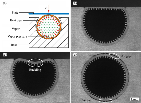
Fig. 1 Principle of PCEA process (a), heat pipe embedded in heat sink by PCEA process (b), heat pipe with buckling (c), and heat pipe embedded in heat sink by transition fit (d)
The simulated result of the PCEA process is shown in Fig. 2. It can be seen that there is a notable buckling on the heat pipe when the operating temperature is too low. As shown in Fig. 2(a), the buckle depths are 0.344 mm and 0.325 mm at 100 ��C and 150 ��C, respectively. With the increase of heating temperature, the buckling phenomenon becomes moderate (the depth of buckle is 0.299 mm at 200 ��C). When the heating temperature exceeds 220 ��C, the buckling phenomenon can be neglected, as shown in Fig. 2(b), which means that the heat pipe can offer a flat contact area for the LED light sources. Therefore, the heating temperature of the PCEA process should be not less than 220 ��C. The sectional view of a heat sink base embedded with a heat pipe using the PCEA process is illustrated in Fig. 1(b), which shows that the experimental result is in high consistency with the FE analysis. Due to the expansion phenomenon that the air gap between the heat pipe and the heat sink and buckling of the heat pipe would be eliminated. This is one of the most important characteristics of the PCEA process, which would lower the requirement of machining accuracy and the production cost. Figure 1(d) shows the sectional view of a traditionally assembled heat pipe heat sink with transition fit. It is observed that the heat pipe cannot sufficiently contact the heat sink, with more than 50% air gap between the heat pipe and the heat sink. Usually, thermal grease is required to fill the air gap to improve the thermal performance. Therefore, it can be expected that the PCEA heat pipe heat sinks would provide a much more excellent thermal performance.
3 Thermal performance measurement
3.1 Sample preparation
Figure 3 displays the exploded view diagram of the LED module. An LED array, composed of 9 LED packages (3 W/package) attached on a metal core print circuit board (MCPCB), was mounted on the heat sink base by two screws. The LED chips used in the experiment were in excellent consistency, so it was assumed that each LED chip exhibited the same thermal and optical performance. A thin layer of thermal grease (1.5 W/(m��K)) was utilized to reduce the thermal resistance between the MCPCB and the base. The evaporator of the heat pipe was embedded into the base and the condenser was inserted into an aluminum fin set. In the first case, the evaporator of the heat pipe was embedded into the base by the PCEA process, namely sample A. In the second case, the evaporator was directly inserted into the base by transition fit, with thermal grease to fill the air gap between the heat pipe and the base, namely sample B. In this experiment, thermal characteristics and optical performance of sample A and B were measured and discussed.
3.2 Transient thermal measurement
Transient thermal measurements were used to explore the thermal characteristics of the LED modules. Measurements were carried out by thermal transient tester (T3Ster, MicRed Ltd), the testing theory of which is on the basis of the JESD51-1 [22]. T3Ster captures the cooling/heating curves to derive the structure function based on the mathematical transformations between the Foster and Cauer representation of RC one-ports [23]. From the structure function, different regions of the heat-flow path of the LED modules can be identified quantitatively.
As schematically illustrated in Fig. 4, the measurement system consisted of the tested LED modules, a T3Ster to supply the power and record the forward voltage, an integrating sphere to measure the spectra and a PC to process the acquisition data. The measurements were performed in the following steps. The first step was to get a K factor based on the following equation:
 (2)
(2)
where K is a ratio of the forward voltage change to the junction temperature change, K is also known as a temperature sensitive parameter (TSP), ��Vf,total is the total voltage change of the LED array, and ��Tj,ave is the change of the average junction temperature. In this process, the LED array was heated to seven stable temperatures, ranging from 20-80 ��C with an increasing step of 10 ��C. And then, the forward voltage was measured using a 1 mA bias current. The second step was to record the cooling curve after driving the LED module to an equilibrium temperature condition. In this experiment, five input powers of the LED array, ranging from 5 W to 25 W in five steps were employed for each sample. Both samples were measured for 3 times at each power to exclude test error. The error margin of the power supply was ��0.5%, and that of the thermalcouples was ��0.1 ��C. The ambient temperature and the humidity of the environment were was (25��1) ��C and 50%��2%.
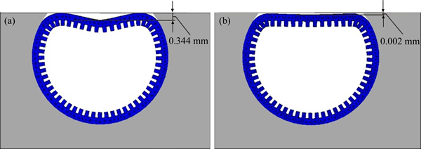
Fig. 2 FE simulated result of PCEA process
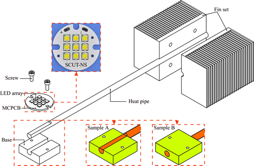
Fig. 3 Exploded view diagram of LED module
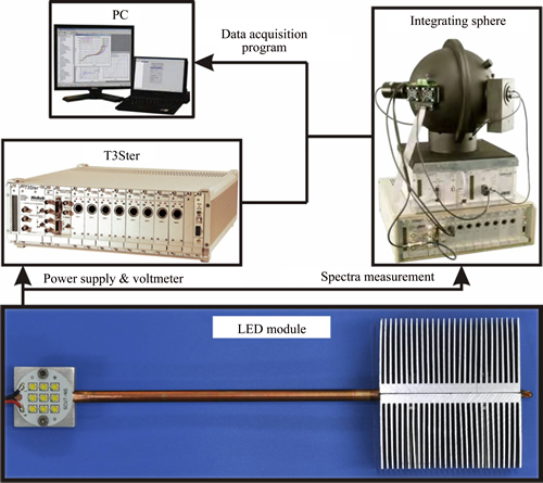
Fig. 4 Schematic diagram of experimental setup
4 Results and discussion
4.1 Heat transfer performance
Figure 5 plots the forward voltage versus junction temperature of the LED array. The linear relationship between the forward voltage and the junction temperature is defined as the K factor. And the measured K factor of the LED array used in the experiment is -0.01127 V/��C at the bias current of 1 mA.
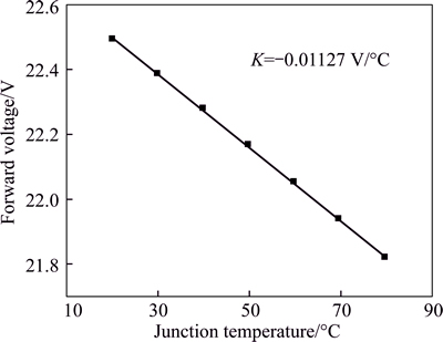
Fig. 5 Forward voltage versus junction temperature plot showing K factor of LED array
Figure 6 shows the obtained structure functions of the LED modules employing different assembly processes. The horizontal and vertical axis respectively represents the thermal resistance and cumulative thermal capacitance along the heat-flow path. The origin of the curve refers to the junction while the right-side end corresponds to the ambient. As revealed in Fig. 6, the total thermal resistance from junction to ambient of sample A (Rj-a,A) and B (Rj-a,B) are 3.65 k/W and 3.84 k/W, which means that Rj-a,A is 0.19 k/W lower than Rj-a,B. In the high power LED applications, the heat transfer performance is quite difficult to be further improved [24]. So, the decreased 0.19 k/W in the thermal resistance is very important in lowering the junction temperature and improving the performance of the LED products.
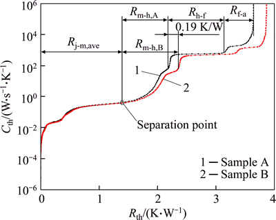
Fig. 6 Structure functions of LED modules operating at 25 W
To explain the deviation of the two samples in the total thermal resistance, equivalent thermal circuits are established, as illustrated in Fig. 7. The main difference between the two thermal circuits lies on the heat-flow path from the MCPCB to the heat pipe (Rm-h). Sample A has two heat-flow paths: 1) directly from the MCPCB to the heat pipe (Rm-h) and 2) firstly from the MCPCB to the base (Rm-b) and then to the heat pipe (Rb-h). However, there exists only one heat-flow path for sample B. All the heat is firstly transferred to the base (Rm-b) and then to the heat pipe (Rb-h). Obviously, path 1 in sample A is a shorter heat-flow path. In addition, the air gap and thermal grease between the base and the heat pipe of sample B would become impediments to heat flow and increase Rb-h. As a result, Rm-h of sample A is lower than that of sample B. The total thermal resistance from junction to ambient can be calculated according to the following equations:

 (3)
(3)
 (4)
(4)
where Rj-m,ave, Rh-f and Rf-a are respectively the thermal resistance from the LED array to the MCPCB, from the heat pipe to the fin set and from the fin set to the ambient. And they are supposed to be the same for both LED modules. Theoretically, the decrease in Rm-h is the main reason to the decrease in Rj-a of sample A.
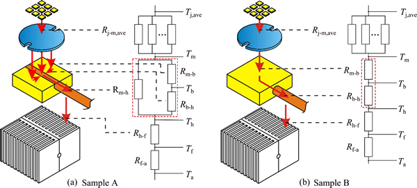
Fig. 7 Thermal resistance circuits of LED modules
Reconsidering the structure functions in Fig. 6, the separation point of the two curves represents the bottom of the MCPCB, where the heat flows into the base and the heat pipe. It is indicated that Rj-m,ave and Rh-a of the two samples are almost the same. However, Rm-h are 0.79 k/W and 0.97 k/W for sample A and sample B respectively, which means that Rm-h,A is about 20% lower than Rm-h,B. Obviously, 20% decrease in the thermal resistance is attributed to the PCEA process. So, in the heat pipe heat sink cooling devices, not only the structure optimization should be considered, but also the assembly process between the heat pipe and the heat sink is very important.
Figure 8 shows Rj-a,ave of the two samples operating from 5 W to 25 W. Obviously, in the whole power range Rj-a,ave of sample A is always lower than that of sample B due to the superiority of the PCEA process. It is also noted that for both samples, Rj-a,ave decreases as the input power increases. Reasonable explanation is that the thermal resistance of the heat pipe varies at different powers. At low input powers, only partial working fluid turns into vapor, while the rest is still in the liquid phase and blocks at the micro-grooved wicks. Therefore, the thermal resistance of the heat pipe is high. As the power increases, the working fluid can sufficiently evaporate and circulate normally, resulting in the decrease of the heat pipe thermal resistance. Similar result has been also found in former research [25].
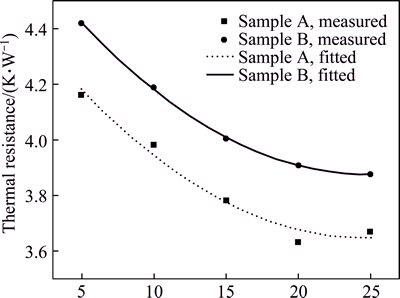
Fig. 8 Thermal resistance from junction to ambient at different powers
Based on the K factor theory, the junction temperature of the LED array can be calculated by the following equation:
 (5)
(5)
where TX is the reference temperature for the specific environment. The measured Tj,ave of the two samples operating from 5 W to 25 W are displayed in Fig. 9. Obviously, Tj,ave increases linearly with the input powers. It is indicated that for sample A and B operating at low input powers, they exhibit the similar junction temperature. At the input power of 5 W, Tj,ave of sample A and B are 40.0 ��C and 40.9 ��C, respectively. Nevertheless, as the input power increases, the effect of the assembly process on the junction temperature of the LED array becomes notable. At 25 W, Tj,ave of sample A and B are 97.5 ��C and 101.6 ��C, respectively. And sample A exhibits 4.1 ��C lower in the junction temperature. Such a deviation in junction temperature can be explained by the difference of the two samples in the heat-flow paths. For sample A, partial contact between the MCPCB and the heat pipe allows a portion of heat directly transfer to the heat pipe. While for sample B, all the heat firstly accumulates on the base and then transfers to the heat pipe. Besides, the introduction of the air gap and thermal grease actually acts as a thermal barrier due to their low thermal conductivity. As a result, the heat transfer efficiency of sample B would be lower. When the LED modules operate at high powers, the difference in Tj,ave is more evident because that heat accumulation on the base is more severe for sample B, resulting in much higher junction temperature than sample A. Considering the heat transfer performance of the LED modules operating at different powers, a recommendation is that in high power LED module applications, the PCEA process is preferred, and the transition fit assembly is acceptable in low power cases for its relatively simple process.
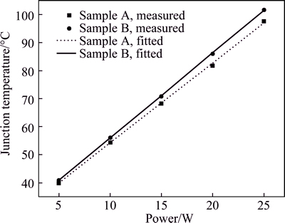
Fig. 9 Average junction temperature of LED arrays operating at different powers
4.2 Optical performance
Figure 10 shows the optical performance of the LED modules operating at 25 W. The spectra were measured by an integrating sphere system. As revealed in Fig. 10, the peak wavelength (around 450 nm) of sample A and B are 446 nm and 447 nm respectively. And that of sample B represents an energy drop of 4 mW/nm compared with sample A. The reasons are attributed to the higher junction temperature of sample B, in which case the energy gap shrinks and results in the shift of the peak wavelength toward longer wavelength [26]. And quantum efficiency decreases and causes more non- radiation recombination in the LED, therefore resulting in the energy drop of the peak wavelength [27]. It is also noted that the phosphor down-converted light also experiences an energy degradation, which is caused by the phosphor thermal quenching effect [28]. Overall, the luminous flux of sample A is 1694 lm and it is about 2% higher than that of sample B. Such an improvement in the luminous flux would have a great significance in the commercial lighting system which consists of a large number of LED components.
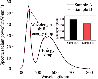
Fig. 10 Optical performance of LED modules operating at 25 W
5 Conclusions
A novelly assembled heat pipe heat sink is developed to improve the thermal performance of an LED module. The heat pipe was embedded into the heat sink by a phase change expansion assembly (PCEA) process. The heat pipe and the heat sink were firstly heated to 200-220 ��C, and a plate was used to flatten the heat pipe outside the groove of the heat sink. Then, the heating temperature was risen to 270-290 ��C. The vapor pressure would force the wall of the heat pipe to expand and contact with the heat sink tightly. Thermal characteristics of the LED module employing the PCEA process (sample A) were experimentally investigated and compared to a LED module with a traditionally assembled heat pipe heat sink (sample B). At the input power of 25 W, the PCEA process significantly lowers the thermal resistance from the MCPCB to the heat pipe by about 20%, therefore lowering the total thermal resistance of the LED module. And the junction temperature is reduced by about 4%. Finally, the optical performance of the LED modules was measured. Results show that the luminous flux of sample A is 2% higher than that of sample B. The improvement in the thermal and optical performance is very important to the high power LED applications. And the findings of this work show that the PCEA process can be a potential thermal management for the LED lighting systems.
Nomenclatures
pv Saturated vapor pressure, 133.32 Pa
T Temperature, ��C
��T Temperature change, ��C
R Thermal resistance, K/W
V Voltage, V
Subscripts
j Junction
m Metal core print circuit board (MCPCB)
b Base
h Heat pipe
f Fin set
a Ambient
ave Average
References
[1] CRAFORD M G. LEDs for solid state lighting and other emerging applications: status, trends, and challenges [C]// Optics & Photonics 2005. International Society for Optics and Photonics, 2005, 594101-594110.
[2] SCHUBERT E F, KIM J K. Solid-state light sources getting smart [J]. Science, 2005, 308: 1274-1278.
[3] STERANKA F, BHAT J, COLLINS D, COOK L, CRAFORD M, FLETCHER R, GARDNER N, GRILLOT P, GOETZ W, KEUPER M. High power LEDs�CTechnology status and market applications [J]. Physica Status Solidi (A), 2002, 194: 380-388.
[4] YUNG K, LIEM H, CHOY H, LUN W. Thermal performance of high brightness LED array package on PCB [J]. International Communications in Heat and Mass Transfer, 2010, 37: 1266-1272.
[5] NARENDRAN N, GU Yi-min. Life of LED-based white light sources [J]. Display Technology, Journal of, 2005, 1: 167-171.
[6] CHHAJED S, XI Y, LI Y L, GESSMANN T, SCHUBERT E. Influence of junction temperature on chromaticity and color- rendering properties of trichromatic white-light sources based on light-emitting diodes [J]. Journal of Applied Physics, 2005, 97: 054506-054508.
[7] LUO Xiao-bing, CHEN Wei, SUN Ren-xia, LIU Sheng. Experimental and numerical investigation of a microjet-based cooling system for high power LEDs [J]. Heat Transfer Engineering, 2008, 29: 774-781.
[8] DENG Yue-guang, LIU Jing. A liquid metal cooling system for the thermal management of high power LEDs [J]. International Communications in Heat and Mass Transfer, 2010, 37: 788-791.
[9] CHENG Hui-huang, HUANG De-shau, LIN Ming-tzer. Heat dissipation design and analysis of high power LED array using the finite element method [J]. Microelectronics Reliability, 2012, 52: 905-911.
[10] CHAU S, LIN C, YEH C, YANG C. Study on the cooling enhancement of LED heat sources via an electrohydrodynamic approach [C]// Industrial Electronics Society, 2007. IECON 2007. 33rd Annual Conference of the IEEE. IEEE, 2007: 2934-2937.
[11] KIM L, CHOI J H, JANG S H, SHIN M W. Thermal analysis of LED array system with heat pipe [J]. Thermochimica Acta, 2007, 455: 21-25.
[12] LI Ji, LIN Feng, WANG Da-ming, TIAN Wen-kai. A loop-heat-pipe heat sink with parallel condensers for high-power integrated LED chips [J]. Applied Thermal Engineering, 2013, 56(1, 2): 18-26.
[13] HSIEH J C, HUANG H J, SHEN S C. Experimental study of microrectangular groove structure covered with multi mesh layers on performance of flat plate heat pipe for LED lighting module [J]. Microelectronics Reliability, 2012, 52: 1071-1079.
[14] WANG Jung-chang, WANG Rong-tsu, CHANG Tien-li, HWANG Daw-shang. Development of 30Watt high-power LEDs vapor chamber-based plate [J]. International Journal of Heat and Mass Transfer, 2010, 53: 3990-4001.
[15] BAI Peng-fei, TANG Yong, TANG Biao, LU Long-sheng. Thermal performance of heat pipe with different micro-groove structures [J]. Journal of Central South University of Technology, 2008, 15 (Supplement 2): 240-244.
[16] http://www.thermalright.com/products.html. 2014.
[17] LU Xiang-you, HUA Tse-chao, WANG Yan-ping. Thermal analysis of high power LED package with heat pipe heat sink [J]. Microelectronics Journal, 2011, 42(11): 1257-1262.
[18] TANG Yong, CHEN Jian-hong, CHEN Wei-bin, LU Long-sheng, OU Dong-sheng, LIAN Bin. Phase-change non-destructive pipe expanding method for inner finned pipe [P]. CN201010140842, 2012. (in Chinese)
[19] GUAN Wo-huan, TANG Yong, DING Xin-rui, LIU Bin, LU Long-sheng. Thermal analysis of edge illumination type LED backlight with heat pipe [J]. Applied Mechanics and Materials, 2013, 401: 339-344.
[20] JIANG Le-lun, TANG Yong, PAN Min-qiang, ZHOU Wei, LU Long-sheng. Phase change flattening process for axial grooved heat pipe [J]. Journal of Materials Processing Technology, 2012, 212: 331-338.
[21] http://en.wikipedia.org/wiki/Antoine_equation. 2014.
[22] JESD51-1. Integrated circuits thermal measurement method- electrical test method [S].
[23] SZ KELY V. Enhancing reliability with thermal transient testing [J]. Microelectronics Reliability, 2002, 42: 629-640.
[24] CHOI J H, SHIN M W. Thermal investigation of LED lighting module [J]. Microelectronics Reliability, 2012, 52: 830-835.
[25] ASIRVATHAM L G, NIMMAGADDA R, WONGWISES S. Heat transfer performance of screen mesh wick heat pipes using silverawater nanofluid [J]. International Journal of Heat and Mass Transfer, 2013, 60: 201-209.
[26] PENG L H, CHUANG C W, LOU L H. Piezoelectric effects in the optical properties of strained InGaN quantum wells [J]. Applied Physics Letters, 1999, 74: 795-797.
[27] LIU Jun, TAM W S, WONG H, FILIP V. Temperature-dependent light-emitting characteristics of InGaN/GaN diodes [J]. Microelectronics Reliability, 2009, 49: 38-41.
[28] SMET P F, PARMENTIER A B, POELMAN D. Selecting conversion phosphors for white light-emitting diodes [J]. Journal of the Electrochemical Society, 2011, 158: R37-R54.
(Edited by YANG Bing)
Cite this article as:
TANG Yong, CHEN Qiu, GUAN Wo-huan, LI Zong-tao, YU Bin-hai, YUAN Wei. Thermal analysis of an LED module with a novelly assembled heat pipe heat sink [J]. Journal of Central South University, 2017, 24(4): 921-928.
DOI:https://dx.doi.org/10.1007/s11771-017-3494-9Foundation item: Projects(51375177, U1401249, 51405161) supported by the National Natural Science Foundation of China; Project(2014M560659) supported by the Postdoctoral Science Foundation of China; Project(2014B090901065) supported by the Science and Technology Planning Project for Industry-University-Research Cooperation in Guangdong Province, China
Received date: 2015-09-28; Accepted date: 2016-03-22
Corresponding author: LI Zong-tao, PhD; Tel: +86-13824460886; E-mail: meztli@scut.edu.cn
Abstract: This work aims to improve the thermal performance of a light emitting diode (LED) module by employing a novelly assembled heat pipe heat sink. The heat pipe was embedded into the heat sink by a phase change expansion assembly (PCEA) process, which was developed by both finite element (FE) analysis and experiments. Heat transfer performance and optical performance of the LED modules were experimentally investigated and discussed. Compared to the LED module with a traditionally assembled heat pipe heat sink, the LED module employing the PCEA process exhibits about 20% decrease in the thermal resistance from the MCPCB to the heat pipe. The junction temperature is 4% lower and the luminous flux is 2% higher. The improvement in the thermal and optical performance is important to the high power LED applications.
