
Trans. Nonferrous Met. Soc. China 28(2018) 757-765
Construction of reasonable pillar group for undersea mining in metal mine
Zhi-xiang LIU, Tian LUO, Xiang LI, Xi-bing LI, Zhen HUAI, Shao-feng WANG
School of Resources and Safety Engineering, Central South University, Changsha 410083, China
Received 28 May 2017; accepted 6 November 2017
Abstract:
In order to achieve the safe mining in Sanshandao Gold Mine, five schemes of secure pillar group are designed. Using the method of the renormalization group, the failure mechanism of the pillar group is explored, and the safety factor of the pillar system is also obtained. The displacement characteristics, stress-strain laws, distribution of plastic zone and damage range of different pillar group are analyzed using numerical calculation software FLAC3D. To determine a reasonable pillar group scheme, the pillar stability and roof deformation are utilized to evaluate the safety of the pillar group. In addition, the theory of fuzzy comprehensive evaluation is adopted to verify the optimal scheme. The pillar group with the lowest roof deformation value is chosen as the optimal plan, which renders a factor of safety of 2.06 for the pillar group. According to this scheme, pillars with the width of 10 m are set along the strike of undersea deposit with the interval of 50 m. Rib pillars of 15 m in width are set at the location of the exploration line of 127, 151 and 167. The analysis can be used to provide guidance for optimal design of pillar structures in undersea mining.
Key words:
undersea mining; pillar group scheme; safety factor; numerical simulation; fuzzy comprehensive evaluation;
1 Introduction
Sanshandao Gold Mine is the first large-scale gold mine in China implementing undersea mining with the production capacity of 15000 t/d. The ore deposit thickness is in the range of 14-45 m, and the dip angle is from 60�� to 75��. Upright and inversion phenomena exist in some locations of the ore body. The gold deposit is close to the major fault F1, with fault gouge of 5-10 cm in thickness. The rock mass of hanging wall is fractured, and the joints and fissures in the ore body further complicate the mining conditions.
There are two special features for the deposits of undersea mines [1-5]. One characteristic is that the deposit is hosted in the seabed, so the corresponding mining technique is quite different from underground mining on land. The other is that if the deformation of seabed is not strictly controlled, water-inrush accidents may occur. In order to ensure the safety in mining operations, it is necessary to set up a rational pillar group to better support the roof and surrounding rocks [6-10]. In the undersea mining process, if a pillar is failed, stress redistributions will occur in the region where the adjacent pillars are located, due to the loss of load bearing ability of the failed pillar. This tends to cause the deformation and settlement in seabed, and consequently leads to the accident with water inrush. Thus, the stability of the pillar group is directly related to the safe exploitation of undersea deposit [11-15]. Therefore, designing the reasonable scheme for ore pillar group becomes an important research subject for Sanshandao Gold Mine.
It is understood that the bearing capacity of a pillar is proportional to its cross-sectional area: the larger the size of the pillar is, the better the stability of the pillar becomes. On the other hand, in order to improve the economic benefit, the mining loss rate should be minimized. Therefore, the pillar size should be as small as possible under the premise of safe mining. Because of its significance in safe and economical extraction of underground ores, mine pillar has been investigated. GRIFFITHS et al [16] combined random field theory with an elasto-plastic finite element algorithm in the Monte Carlo framework to estimate the stability of pillars. CAUVIN et al [17] used probabilistic method to assess uncertainties in mine pillar stability. PALEI and DAS [18] presented a logistic classification model for the prediction of roof fall risks in board and pillar workings in coal mines. JAISWAL and SHRIVASTVA [19] and MOHAN et al [20] respectively established a three-dimensional finite element model for the estimation of coal-mass pillar strength with calibrated numerical models. LI et al [21] successfully determined the thickness of the crown pillar of Sanshandao Mine with the help of the FLAC3D software. BRADY and BROWN [22] obtained the empirical index formula of the relationship between pillar strength and its size and geometry. Considering the influence of burial depth, ZHAO et al [23] deduced a new formula of pillar size using Protodyakonov��s theory. ZHOU et al [24] applied statistical and soft computing methods such as Fisher discriminant analysis (FDA) and support vector machines (SVMs) methodology to determine the pillar stability for underground mines. YAO et al [25] studied the sensitivity of the pillar stability to its influencing factors. LIU et al [26] optimized the stope parameters with numerical simulation and chaos optimization algorithm. The above researches provide useful references for the construction of rational pillar group for undersea mining.
The purpose of this work is to determine the reasonable pillar structure in seabed deposit. The mechanical model and the fractal tree model of pillar group are established based on the renormalization group method [27]. The safety factor of pillar is also obtained. In addition, five schemes of secure pillar group are proposed, and the stress state of ore pillars, the displacement of surrounding rocks and the range of plastic zones are analyzed using the numerical calculation software FLAC3D. Based on the technical and economical indexes of the five schemes, the evaluation indexes of each scheme are quantitatively analyzed by the method of fuzzy comprehensive evaluation. Finally, a reasonable scheme of pillar group is selected. The analysis in this work will provide the theoretical basis for the undersea mining design in Sanshandao Gold Mine.
2 Numerical model and construction schemes of pillar group
2.1 Geometry of numerical model
The undersea ore body in Sanshandao Gold Mine is located between exploration line of 119-159, with the thickness of 14-45 m and dip angle of 65��-75�� (Fig. 1). According to the profiles of exploration line from 115 to 171 and the geological plans of -165, -200, -240, -280 and -400 m level, the numerical model of undersea mining is established using FLAC3D (Fig. 2). The dimension of the model is 700 m along the ore strike, 500 m in the direction perpendicular to the strike and 600 m below the sea level in vertical direction. The ore body strike, the direction perpendicular to the strike and the vertical orientation are defined in the model as X-axis direction, Y-axis direction and Z-axis direction, respectively. The model consists of six parts: seawater, sea mud, bedrock, hanging wall rock, foot wall rock and ore body.

Fig. 1 Top view of ore body in Sanshandao Gold Mine

Fig. 2 Model geometry of undersea mining
The aim of the numerical simulation is to analyze the displacement characteristics, stress-strain conditions, distribution of plastic zones and damage range of different schemes. Mohr-Coulomb constitutive model is adopted in the numerical analysis and the following boundary conditions are applied in the model: (1) fixed X-direction displacement at the left and right boundaries; (2) fixed Y-direction displacement at the front and back boundaries; (3) fixed all the X, Y and Z direction displacements at the bottom; (4) free boundary at the top of the model.
The in-situ stress is composed of gravity stress and tectonic stress. The relationships between the values of principal stresses and buried depth are obtained by the in-situ stress measurement in Sanshandao Gold Mine. The FLAC3D uses the general engineering convention of compression being negative and tension being positive. And the X-axis direction and Y-axis direction stresses in the model are deduced by projecting the horizontal maximum principal stress and the minimum principal stress on the X and Y axes, respectively. The data generated by the model are consistent with the actual measurement, and the input value of the numerical mode can be written as
��X=-28.78+0.0478Z (1)
��Y=-10.158+0.0168Z (2)
��Z=-18.98+0.0315Z (3)
where ��X , ��Y and ��Z are the stresses in X-axis direction, Y-axis direction and Z-axis direction, respectively, MPa; Z denotes the depth below sea level, m.
According to the rock mechanical test results in Sanshandao Gold Mine, the mechanical parameters used in the numerical simulation are given in Table 1. In addition, the sea water density is set to be 1.01 g/cm3, and the densities of gravel and mud in sea floor are set to be 1.80 and 1.70 g/cm3, respectively.
Table 1 Mechanical parameters in numerical simulation

2.2 Numerical model of pillar group schemes
Due to the limitation of actual mining conditions, existing development system, mining equipment and mining method in Sanshandao Gold Mine, the following five schemes of pillar group are proposed. Scheme 1: the 10 m-wide pillars are set with the interval of 50 m in the undersea deposit, with rib pillars of 15 m in width set at the location of the exploration line of 127, 151 and 167 (Fig. 3). Scheme 2: the 10 m-wide pillars are set with the interval of 50 m along the ore strike. Scheme 3: the 10 m-wide pillars are set with the interval of 100 m, and the 5 m-wide pillars are set in other regions with interval of 50 m. Scheme 4: the 10 m-wide pillars are set with the interval of 50 m, and at the locations of the exploration line of 127-131, 151-155 and 167-171, with the width of the vertical pillars of 50, 50 and 30 m, respectively. Scheme 5: the 10 m-wide pillars are set with the interval of 100 m, and the 5 m-wide pillars are set in other regions with interval of 50 m. In addition, on the exploration line of 127-131,151-155 and 167-171, the widths of three vertical pillars are set to be 50, 50 and 30 m, respectively. In the five schemes of pillar group, the thickness of the roof and the floor is set to be 6 m, and the pillars can be exploited by upward drift filling mining method after the whole deposit has been completely mined. The mining rates of the five schemes are 70.34%, 72.19%, 76.87%, 63.23% and 66.03%, respectively, where the mining rate of Scheme 3 is the highest, and the mining rate of Scheme 4 is the lowest.
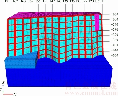
Fig. 3 Illustration of pillar group in Scheme 1
3 Theory of renormalization group method and fuzzy mathematics method
3.1 Theory of renormalization group method
During the exploitation of undersea deposits, pillar group can form a support structure for the surrounding rock, and the load from roof rocks is mainly supported by the pillar group. The most important problem is whether the stability of the entire pillar group will be affected if one pillar is destroyed, or to what level should the safety factor of pillar be attained, to guarantee the stability of the whole pillar system. To study the failure mechanisms of the pillar group in undersea mining, the renormalization group method is adopted to analyze the force distribution within the pillar group [28,29]. The renormalization group method can quantitatively obtain the change of the physical quantity by changing the observation size. This method can obtain the characteristic description of the macroscopic system by performing a series of self-similar transformations on the basic components of the system. The loading model of roof of goaf area is shown in Fig. 4, and the fractal tree model of pillar group is shown in Fig. 5. As can be seen in the basic model shown in Fig. 5(a), the force F is added to the two sides of primary structural unit. If the pillar is destroyed on one side of the unit, the force will be transferred to the other side of the structural unit, which will be subjected to a force of 2F. The three hierarchy model on basic model for pillar group can be seen in Fig. 5(b), where the top force of the three-level structure unit is 8F.
Assuming that the failure probability of the pillar structural unit obeys Weibull distribution:
R0(F)=1-exp(-F/F0) (4)
where R0 (F) is the failure probability of Level 0; F is the load of a single pillar; F0 is the reference strength of a single pillar.
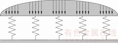
Fig. 4 Loading model for roof and goaf

Fig. 5 Fractal tree model for pillar failure
In this structure, the failure probability of both the primary unit and the whole three-level unit can be obtained using the same method. Then, the result can be generalized to the failure probability relationship between Level Rn+1 and Level Rn:
 (5)
(5)
where Rn+1 is the failure probability of Level n+1; Rn is the failure probability of Level n.
To study the relationship between Rn+1 and Rn, Eq. (5) is written as follows:
f(x)=x2(3-2x) (6)
Setting f(x)=x, then x=x2 (3-2x) is a cubic equation. By solving this equation, three solutions are obtained within the range of 0��x��1, which are respectively x1=0, x2=0.5 and x3=1. Iteration results of Eq. (5) show that x2=0.5 is a critical point. If the failure probability is less than 0.5, Rn will approach 0 in the iterative process, and the system will be stable (as shown in Fig. 6). If the damage probability is higher than 0.5, Rn will approach 1, and the system tends to be destroyed.
According to the critical point R0=0.5 (Eq. (6)), the value of F/F0 is obtained to be 0.693. Supposing K to be the safety factor of a single pillar, then K is expressed as K=F0/F. Therefore, to maintain the stability of the pillar group during undersea mining, the safety factor of each pillar should be higher than 1.44.
3.2 Theory of fuzzy mathematics method
The choice of mining scheme is a complicated decision-making process involving multiple factors and objectives [30]. However, conventional mining method is determined only by a single or several influencing factors that are intuitively evaluated, which involves many experiential factors. Fuzzy mathematics provides a theoretical basis for the fuzzy concept, fuzzy reasoning, fuzzy judgment and fuzzy decision digitization and quantification which can only be described qualitatively in complex system design process. But the weight of complex index system is selected through the subjective review of experts, with a certain degree of subjectivity. Analytic hierarchy process (AHP) can systematize the various factors of complex system problems by dividing the orderly levels of interlinkages, and quantify the relative importance of each level according to the judgment of certain objective reality. Thus, the weight of the relative importance of all the elements of each level is determined according to the mathematical method.
The combination of AHP and fuzzy mathematics theory is applied to the evaluation of the pillar group schemes. The comprehensive evaluation index system of each scheme is established, and the weight of each factor is objectively determined by analytic hierarchy process. Then, the fuzzy comprehensive evaluation is established according to fuzzy mathematics theory, in order to determine the optimal pillar group scheme.
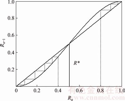
Fig. 6 Iteration expressions between Rn+1 and Rn
4 Numerical simulation analysis and scheme optimization of pillar group in undersea mining
4.1 Results of numerical simulation
Cemented fill mining method is applied in Sanshandao Gold Mine, which means that the mining goaf is backfilled in time. According to the characteristics of this mining method, the numerical simulation is performed to analyze the stress state of the pillar group, the maximum displacement of the roof rock and the distribution of plastic zone in the pillar group.
4.1.1 Stress analysis of pillar group
The stress distribution in the five schemes of pillar group is analyzed, where the maximum tensile stress and the maximum compressive stress in the pillar group are obtained. Taking Scheme 1 as an example, the cloud picture of the maximum principal stress and minimum principal stress in the pillar group are shown in Fig. 7 and Fig. 8, respectively.

Fig. 7 Maximum principal stress in Scheme 1

Fig. 8 Minimum principal stress in Scheme 1
The calculating results show that, from Scheme 1 to Scheme 5, the average values of maximum compressive stress at the region of pillar are 23.33, 25.83, 29.17, 20.42 and 22.08 MPa, respectively, and the average values of minimum tensile stress at the region of pillar are 0.78, 0.78, 1.00, 0.50 and 0.50 MPa, respectively. The strength of the pillar is 48 MPa, and the safety factors of pillars from Scheme 1 to Scheme 5 are calculated to be 2.06, 1.86, 1.64, 2.35 and 2.17, respectively. The safety factor in each pillar scheme is higher than 1.44, so the stability of the pillar group can be guaranteed.
According to the numerical simulation results, the larger the cross-sectional area of pillar is, the smaller the compressive stress in the pillar group becomes. With a larger cross-sectional area, the safety factor of the pillar group is also higher. In other words, the reasonable size of pillar will be beneficial in the improvement of the stress distribution of the whole mining area. On the other hand, if the cross section of pillar is too large, the mining recovery will reduce, and the corresponding ore loss will increase.
4.1.2 Maximum displacement analysis on roof strata
Fourteen observation points are set with a certain distance between each other in the model, as shown in Fig. 9. The displacement of the roof strata can be obtained from each observation point, and the control effect of each scheme on the settlement of roof strata can also be analyzed. The maximum displacement of the roof strata in each scheme is obtained with the vector diagram of global displacement, which can reflect the control effect of the pillar group on the global displacement. Taking Scheme 1 as an example, the position of observation points and displacement conditions are shown in Fig. 9, and the vector diagram of global displacement is shown in Fig. 10.

Fig. 9 Displacement in ore body and observation points

Fig. 10 Vector diagram of global displacement
According to the calculation results, the vertical displacement at each observation point is shown in Fig. 11. The maximum vertical settlements of roof strata from Scheme 1 to Scheme 5 are 1.72, 1.73, 1.98, 1.76 and 1.88 cm, respectively, and the maximum displacements are 2.62, 3.00, 3.63, 2.93 and 3.20 cm, respectively. The results show that Scheme 1 is the best for the displacement control of the roof strata (the smallest maximum displacement), followed by Scheme 4, Scheme 2, Scheme 5 and Scheme 3.
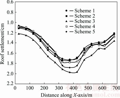
Fig. 11 Vertical settlement curves of roof strata in different schemes
4.1.3 Distribution of plastic zones in pillar group
The distributions of plastic zones with different pillar group schemes are shown in Fig. 12. Shear failure of backfill has been observed in all 5 schemes, due to the low strength of the backfill material. It is also observed that the common failure mode for roofs is tensile failure, while the pillars generally undergo shear failure. In Fig. 12, both tensile failure and shear failure have the state of ��-n��, which means the zone is in the failure currently, and the state of ��-p��, which means the zone has failed in the past, but currently the stresses fall below the yield surface. Thus, both failure states can provide information about damage regions through the calculation process of the numerical model.

Fig. 12 Plastic zone distributions of pillar group in different schemes
It is seen in Fig. 12 that, small parts of plastic zones of pillar group exist in Scheme 1, and most of the pillar failure mode is in shear-p failure. The size of plastic zones of pillar group in Scheme 2 is larger: some of the pillars at exploration line 119 and 115 are in the state of shear failure (-n), and the rest plastic zones have also experienced the state of shear failure (-p). The size of plastic zones of pillar group in Scheme 3 is the largest: most of the pillars at the exploration line 115, 119 and 131 are in the state of shear failure (-n), and most of the rest pillars have also failed in shear (-p). In Scheme 4 and Scheme 5, the size of plastic zones on the large-sized pillars is relatively small, and the size of plastic zones on the remaining pillars is large. Most plastic zones have failed in shear (-p), and a few pillars at exploration line 119 and 115 are in the state of shear failure (-n). Fewer yielding zones are observed at roofs in Scheme 1 than other schemes, which is also in agreement with the roof settlement data shown in Fig. 11. This indicates that the roof is more stable in Scheme 1. It is also observed that the size of plastic zones in Scheme 1 is smaller than that in other schemes.
4.2 Scheme optimization of pillar group
Due to the fact that the above five schemes of pillar group have their own merits and flaws, some of the evaluation indexes have the characteristics of fuzziness, randomness and unpredictability. Therefore, the fuzzy comprehensive evaluation method is adopted to convert various fuzzy or subjective factors into data. Thus, the evaluation indexes of each scheme can be quantitatively analyzed, and accordingly the optimal pillar group scheme can be selected.
(1) Synthetic evaluation indexes
By analyzing the above researching results, seven indexes are selected (as given in Table 2), which are divided into qualitative and quantitative indexes. The mean maximum tensile stress, mean maximum compressive stress, maximum displacement and mining rate are chosen as quantitative indexes, and the range of plastic zones, suitability of the scheme and difficulty degree of the implementation are chosen as qualitative indexes.
(2) Membership degree of quantitative indicators
If there are n schemes and m indicators in every scheme, the characteristic value matrix can be written as follows:
 (7)
(7)
where i=1, 2, ��, m, and j=1, 2, ��, n. In the matrix of the study, n=5 and m=7.
The calculating methods of relative membership degree are described as follows:
If the maximum value is optimum index, the following equation for normalization is used:
��ij=yij/yi,max (8)
If the minimum value is optimum index, the following equation for normalization is used:
��ij=1-yij/yi,max (9)
There are four quantitative indexes and three qualitative indexes in the above five schemes. According to the parameters of the quantitative indicators (given in Table 2), the eigenvector matrix is normalized as follows:

(3) Membership degree of qualitative indicators
According to the qualitative indexes (given in Table 2), the membership degree of qualitative indicators is obtained by checking the mood operators and quantitative scales. The vector of the relative membership degree of the plastic zones, the scheme suitability and the difficulty degree of the implementation are R5=[0.92, 0.52, 0.14, 1, 0.21], R6= [0.87, 0.67, 0.18, 1, 0.33] and R7=[0.45, 0.31, 0.22, 1, 0.59], respectively.
(4) Optimal selection of pillar group scheme
Using AHP, the weight matrix of seven indexes can be obtained, and the maximum eigenvalue is calculated as ��max=7. The consistency check for the judgment matrix can be performed by following equations:
C=I/R (10)
I=(��max-n)/(n-1) (11)
where C is the consistency ratio; I is the consistency index; R is the mean random consistency index; n is the order of the judgment matrix.
The value of R is selected according to Table 3.
Table 2 Evaluation indexes of pillar group schemes

Table 3 Values of mean random consistency index R

C can be obtained by calculation (C=I/R=0<0.1), which meets the consistency check. By using the root method, the weight vector �� can be obtained as ��= [0.112, 0.092, 0.238, 0.268, 0.231, 0.031, 0.028].
The weighted average model is adopted to evaluate the above five schemes. The subordinated vector can be calculated to be S=[0.89, 0.76, 0.60, 0.87, 0.70]. According to the principle of maximum membership degree, the larger the value of S is, the better the scheme becomes. The results show that Scheme 1 (10 m-wide pillars along the strike of undersea deposit with the interval of 50 m, with 15 m-wide rib pillars at the exploration line of 127, 151 and 167) is the best scheme, followed by Scheme 4, Scheme 2, Scheme 5 and Scheme 3.
5 Conclusions
1) To ensure the mining safety in Sanshandao Gold Mine, five pillar group schemes are proposed, and the failure models of pillar group are established using the renormalization group method. The failure mechanisms of the pillar group are also explored. The results show that the bearing stress in the pillar should not exceed 69.3% of its compressive strength, which means, to ensure the overall stability of the pillar group, the safety factor of each pillar should be higher than 1.44.
2) According to the actual mining conditions in Sanshandao Gold Mine, five numerical models of pillar group schemes are established. The stress variation characteristics, distributions of the plastic zones of the pillar group, and the settlement of the roof strata are investigated. The results show that reasonable cross-sectional area of pillar will be beneficial in the improvement of the stress distribution in the whole mining area.
3) The analysis shows that the roof settlement is the lowest in Scheme 1, and the corresponding factor of safety for the pillars is 2.06. In addition, considering the multi-factorial nature in the optimal mining process, fuzzy comprehensive evaluation method is used to compare these five schemes. The result indicates that Scheme 1 is the optimal scheme for the pillar group, which is in agreement with the analysis of roof deformation and safety factor of pillar group. In this case, 10 m-wide pillars are set along the strike of undersea deposit with the interval of 50 m, with 15 m-wide rib pillars at the exploration line of 127, 151 and 167. The results in this work can help to guide the design of the optimal pillar group structure for undersea mines.
References
[1] LI Xi-bing, LIU Zhi-xiang, PENG Kang, ZHAO Guo-yan, PENG Shu-quan. Theory and practice of rock mechanics related to exploitation of undersea metal mine [J]. Chinese Journal of Rock Mechanics and Engineering, 2010, 29(10): 1945-1953. (in Chinese)
[2] LIU Zhi-xiang, XIAO Si-you, WANG Wei-hua, LI Xi-bing, LAN Ming. Pipeline transportation of backfilling slurry with high filling times line and strong resistance in undersea mining [J]. The Chinese Journal of Nonferrous Metals, 2016, 26(8): 1802-1810. (in Chinese)
[3] LIU Ai-hua, DONG Lei, DONG Long-jun. Optimization model of unascertained measurement for underground mining method selection and its application [J]. Journal of Central South University of Technology, 2010, 17(4): 744-749.
[4] CHUNG J S. Deep-ocean mining: Technologies for manganese nodules and crusts [J]. International Journal of Offshore and Polar Engineering, 1996, 6(4): 244-254.
[5] PENG Kang, LIU Zhao-peng, ZHANG Yong-liang, Fan Xiang, CHEN Qin-fa. Determination of isolation layer thickness for undersea mine based on differential cubature solution to irregular Mindlin plate [J]. Journal of Central South University, 2017, 24(3): 708-719.
[6] LIU Zhi-xiang, DANG Wen-gang, HE Xian-qun, LI Di-yuan. Cancelling ore pillars in large-scale coastal gold deposit: A case study in Sanshandao gold mine, China [J]. Transactions of Nonferrous Metals Society of China, 2013, 23(10): 3046-3054.
[7] PENG Kang, LI Xi-bing, WAN Chuan-chuan, PENG Shu-quan, ZHAO Guo-yan. Safe mining technology of undersea metal mine [J]. Transactions of Nonferrous Metals Society of China, 2012, 22(3): 740-746.
[8] TESARIK D R, SEYMOUR J B, YANSKE T R. Long-term stability of a backfilled room-and-pillar test section at the Buick Mine, Missouri, USA [J]. International Journal of Rock Mechanics and Mining Sciences, 2009, 46(7): 1182-1196.
[9] GHASEMI E, ATAEI M, SHAHRIAR K, SERESHKI F, JALALI S, RAMAZANZADEH A. Assessment of rock fall risk during retreat mining in room and pillar coal mines [J]. International Journal of Rock Mechanics and Mining Sciences, 2012, 12(54): 80-89.
[10] GHASEMI E, SHAHRIAR K. A new coal pillars design method in order to enhance safety of the retreat mining in room and pillar mines [J]. Safety Science, 2012, 50(3): 579-585.
[11] LIU Zhi-xiang, DANG Wen-gang, HE Xian-qun. Undersea safety mining of the large gold deposit in Xinli District of Sanshandao Gold Mine [J]. International Journal of Minerals, Metallurgy and Materials, 2012, 19(7): 574-583.
[12] LI Yuan-hui, NAN Shi-qing, ZHAO Xing-dong, YANG Tian-hong, TANG Chun-an, ZHANG Yong-bin, TAN Zhi-hong. Stability of boundary pillar for transition from open pit to underground mining [J]. Chinese Journal of Rock Mechanics and Engineering, 2005, 24(2): 278-283. (in Chinese)
[13] LIU Zhi-xiang, DANG Wen-gang. Rock quality classification and stability evaluation of undersea deposit based on M-IRMR [J]. Tunnelling and Underground Space Technology, 2014, 40(2): 95-101.
[14] KUMAR P, KIRAN S, CHOUDHURY P B. Pillar and roadway stability assessment of development working of a metal mine with rock mechanics instrumentation��A case study [J]. Journal of Mines, Metals and Fuels, 2010, 58(5): 109-111.
[15] BIENIAWSKI, Z, T. Rock mechanics design in mining and tunneling [M]. Rotterdam: A.A Balkema Publishers, 1984.
[16] GRIFFITHS D V, FENTON G A, LEMONS C B. The random finite element method (RFEM) in mine pillar stability analysis [J]. Probabilistic Methods in Geotechnical Engineering, 2007, 491: 271-294.
[17] CAUVIN M, VERDE T, SALMON R. Modeling uncertainties in mining pillar stability analysis [J]. Risk Analysis, 2009, 29(10): 1371-1380.
[18] PALEI S K, DAS S K. Logistic classification model for prediction of roof fall risks in bord and pillar workings in coal mines: An approach [J]. Safety Science, 2009, 47(1): 88-96.
[19] JAISWAL A, SHRIVASTVA B K. Numerical simulation of coal pillar strength [J]. International Journal of Rock Mechanics and Mining Sciences, 2009, 46(4): 779-788.
[20] MOHAN G M, SHEOREY P R, KUSHWATA A. Numerical estimation of pillar strength in coal mines [J]. International Journal of Rock Mechanics and Mining Sciences, 2001, 38: 1185-1192.
[21] LI Xi-bing, LI Di-yuan, LIU Zhi-xiang, ZHAO Guo-yan, WANG Wei-hua. Determination of the minimum thickness of crown pillar for safe exploitation of a subsea mine based on numerical modeling [J]. International Journal of Rock Mechanics and Mining Sciences, 2013, 57(1): 42-56.
[22] BRADY B G H, BROWN E T. Rock mechanics for underground mining [M]. LI Xi-bing, DONG Long-jun, trans. Beijing: Science Press, 2010: 326-328. (in Chinese)
[23] ZHAO Guo-yan, ZHOU Li, LI Jin-yue, YU Pei-pei. Reasonable pillar size design and nugget structural parameters optimization in room-and-pillar mining [J]. Journal of Central South University (Science and Technology), 2014, 45(11): 3943-3948. (in Chinese)
[24] ZHOU jian, LI Xi-bing, SHI Xiu-zhi, WEI Wei, WU Bang-biao. Predicting pillar stability for underground mine using Fisher discriminant analysis and SVM methods [J]. Transactions of Nonferrous Metals Society of China, 2011, 21(12): 2734-2743.
[25] YAO Gao-hui, WU Ai-xiang, WANG Yi-ming, XIA Hong-chun. Stability analysis of stope retention pillars in broken rock conditions [J]. Journal of University of Science and Technology Beijing, 2011, 33(4): 400-405. (in Chinese)
[26] LIU Qin, LIU Zhi-xiang, LIU Ai-hua, LI Wei. Chaotic optimization of structural parameters in gold mining field [J]. Journal of Mining and Safety Engineering, 2010, 27(4): 548-552. (in Chinese)
[27] XIE He-ping. Introduction to fractal-rock mechanics [M]. Beijing: China Science Publication, 1996. (in Chinese)
[28] HARLOW D G, PHOENIX S L. Probability distributions for the strength of fibrous materials under load sharing ��: Two-level failure and edge effects [J]. Advances in Applied Probability, 1982, 14(1): 68-94.
[29] DONALD L TURCOTTE, Fractual and Chaos in Geology Geophysics [M]. Cambridge: Cambridge University Press, 1993.
[30] WANG Xin-min, ZHAO Bin, ZHANG Qin-li. Mining method choice based on AHP and fuzzy mathematics [J]. Journal of Central South University (Science and Technology), 2008, 39(5): 875-880. (in Chinese).
�������ɺ���������ܹ���
��־�飬�� �죬�� �죬��Ϧ������ �����ٷ�
���ϴ�ѧ ��Դ�밲ȫ����ѧԺ����ɳ 410083
ժ Ҫ��Ϊʵ����ɽ����İ�ȫ���ɣ����5�ֱ����������跽��������������Ⱥ������̽������Ⱥ���ƻ��������ó���֤�����ɵĿ�����ȫϵ����ͨ��FLAC3D��ֵģ�⣬��5�ֿ�����ܹ����������м��㣬������ͬ����������跽����λ��������Ӧ��-Ӧ���ݻ����ɡ��������ֲ����ƻ���Χ���Զ�������������İ�ȫϵ���������ۣ��Ӷ�ѡ�������Ŀ�����ܷ��������⣬����ģ���ۺ����з�����ѡ������ܹ�������������֤����ѡ������ѷ����Ŀ�����ȫϵ��Ϊ2.06�����Ҷ���λ������С���˷����ؿ�������ÿ��50 m����10 m��������127��151��167��̽������15 m���������о��Ժ����ɿ����ṹ���Ż���ƾ���ָ�����塣
�ؼ��ʣ������ɣ������ܹ�����ȫϵ������ֵģ�⣻ģ���ۺ����з�
(Edited by Bing YANG)
Foundation item: Project (41630642) supported by the Key Project of National Natural Science Foundation of China; Projects (51674288, 11402311) supported by the National Natural Science Foundation of China
Corresponding author: Shao-feng WANG; Tel: +86-18073369486; E-mail: wsfcumt@163.con
DOI: 10.1016/S1003-6326(18)64708-9
Abstract: In order to achieve the safe mining in Sanshandao Gold Mine, five schemes of secure pillar group are designed. Using the method of the renormalization group, the failure mechanism of the pillar group is explored, and the safety factor of the pillar system is also obtained. The displacement characteristics, stress-strain laws, distribution of plastic zone and damage range of different pillar group are analyzed using numerical calculation software FLAC3D. To determine a reasonable pillar group scheme, the pillar stability and roof deformation are utilized to evaluate the safety of the pillar group. In addition, the theory of fuzzy comprehensive evaluation is adopted to verify the optimal scheme. The pillar group with the lowest roof deformation value is chosen as the optimal plan, which renders a factor of safety of 2.06 for the pillar group. According to this scheme, pillars with the width of 10 m are set along the strike of undersea deposit with the interval of 50 m. Rib pillars of 15 m in width are set at the location of the exploration line of 127, 151 and 167. The analysis can be used to provide guidance for optimal design of pillar structures in undersea mining.
