

Finite element analysis of stress at implant-bone interface of dental implants with different structures
CHEN Liang-jian1, 2, HE Hao2, LI Yi-min2, LI Ting2, GUO Xiao-ping1, WANG Rui-fang1
1. The Third Xiangya Hospital, Central South University, Changsha 410013, China;
2. State Key Laboratory of Powder Metallurgy, Central South University, Changsha 410083, China
Received 23 December 2010; accepted 16 June 2011
Abstract:
The effect of structure, elastic modulus and thickness of lower modulus layer in porous titanium implants on the stress distribution at the implant�Cbone interface was investigated. Three-dimensional finite element models of different titanium implants were constructed. The structures of the implants included the whole lower modulus style (No.1), bio-mimetic style (No.2), the whole lower modulus style in cancellous bone (No.3) and the whole dense style No.4. The stress distributions at bone�Cimplant interface under static loading were analyzed using Ansys Workbench 10.0 software. The results indicated that the distribution of interface stress is strongly depended on the structure of the implants. The maximum stresses in cancellous bone and root region of implant No.2 are lower than those in the other three implants. A decrease in the modulus of the low modulus layer facilitates the interface stress transferring. Increasing the thickness of the low modulus layer can reduce the stress and induce a more uniform stress distribution at the interface. Among the four implants, biomimetic style implant No.2 is superior in transferring implant�Cbone interface stress to surrounding bones.
Key words:
titanium implant; elastic modulus; finite element analysis; porous structure;
1 Introduction
Titanium and titanium alloys have become the preferred materials for dental implants owing to their good biocompatibility, excellent corrosion resistance and suitable mechanical properties. However, the existing titanium implants still have several drawbacks. Firstly, the bonding strength at the interface between the implant and the bone is not high enough and the biological fixation has not been achieved. Secondly, there exist mismatches between the elastic modulus of the implant and the bone. A stress shielding or concentration can be easily induced on the interface and results in a potential risk to the long-term stability of the implant. The success or failure of an implant is determined by the manner that the stresses at the bone-implant interface transfer to the surrounding bones [1-2]. The mandible has structural characteristic of an outer layer of dense cortical bone and an inner layer of porous cancellous bone. The elastic modulus and mechanical properties of cortical bones are different from those of cancellous bones. Nevertheless, current dental implants are mainly fabricated using dense titanium and titanium alloys, which have no features representing the difference between the inner and outer layers of the mandible or that between their elastic moduli. And therefore, the incompatibility of the mechanical properties between the implant and the bone was encountered. The use of porous metal implants for medical applications has two main advantages. One is the similar elastic modulus to the bone, which helps to prevent the stress shielding effect at the bone interfaces. The other is that it can provide a structural condition for the bone ingrowth to achieve biological fixation [3-4]. However, the low mechanical strength limits their further applications in the implanting industry. In this study, according to the structural characteristics of the mandible and the clinical requirements for the mechanical properties of implant, a novel bio-mimetic design of implant is proposed for the titanium implants, which is composed of a cortical bone zone with a dense structure and a cancellous bone zone with a porous outer layer and a dense core, as well as another three implants with different structures.
The finite element method is one of the most frequently used methods in stress analysis in both industry and science [5]. Three-dimensional (3-D) finite element analysis (FEA) has been widely used for the quantitative evaluation of stresses on the implant and its surrounding bone [6-7]. Therefore, FEA was selected for use in this study to examine the effect of the structure and elastic modulus of dental implant on the stress distribution at implant-bone interface. The 3-D models of the designed implants were constructed and the finite element analyses were carried out using Ansys Workbench 10.0. The stress distributions on implant-bone interface were investigated under static loading condition in order to provide design guidelines for the development of new implants.
2 Materials and methods
2.1 CAD and finite element modeling of elements
A 3-D model of a mandibular section of bone with a missing second premolar and its superstructures were used in this study. A mandibular bone model was selected according to the classification system of Lekholm and Zarb. Trabecular bone was modeled as a solid structure in cortical bone. A bone block with dimensions of 20 mm��14 mm��35 mm, representing the section of the mandible in the second premolar region, was modeled. It consisted of a spongy center surrounded by cortical bone of 2 mm.
Four implant models with the dimensions of d4.1 mm��12 mm were selected in this study. Those implants and abutment were assumed to consist of the same material. Implant No.1 had a whole lower elastic modulus. Implant No.2 was bio-mimetic with a high modulus in the cortical bone zone and low modulus-outer and high modulus-interior in the cancellous bone zone. Implant No.3 had a high modulus in the cortical bone zone and a low modulus in the cancellous bone zone. Implant No.4 was dense with a low elastic modulus. The elastic modulus of the dense titanium (high modulus) was set as 103.4 GPa. The elastic modulus of implant No.1 (low modulus) was set as 40% of the dense titanium. To investigate the effect of elastic modulus on the interface stress, modulus in the low modulus zone varied in the range of 80%, 40%, 10% and 1.3% of the modulus of the dense titanium, i.e. 1 370 MPa. The mechanical properties of the implants are listed in Table 1.
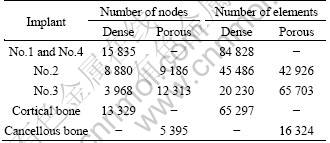
The 3-D model of the implants was constructed by the CAD software Pro/E. The finite element analyses were carried out using Ansys Workbench 10.0. Tetrahedron elements in implant and bone corresponding to SOLID45 type elements in ANSYS element library with each node had three degrees of freedom. The finite element model is shown in Fig. 1. The physical interactions at implant�Cbone interfaces during loading were taken into account through bonded surface-to- surface contact features of ANSYS. Numbers of nodes and elements of implant and bones are listed in Table 2.
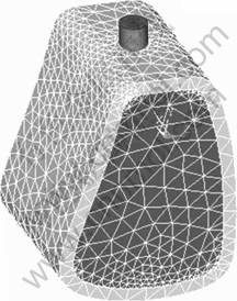
Fig. 1 Finite element model of bone and implant
Table 1 Mechanical properties of materials used in the study
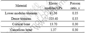
Table 2 Numbers of nodes and elements of implant and bones
2.2 Loads and boundary conditions
All materials were assumed to be homogenous, isotropic and linearly elastic. The bone-implant interfaces were assumed to be 100% osseointegrated. The sides and bottoms of cortical and cancellous bones were set to be completely constrained, and the boundary conditions were extended to the corresponding node. Multi-constraining was imposed on implant from bottom to top, in order to limit the freedom of the roots. Static loading was loaded to evaluate the implant-bone model. The implants were assumed to be under an axial force of 50-300 N and a lingual force of 25 N in the angle of approximately 45�� to the occlusal plane.
The von Mises stresses were utilized as the key indicators to measure stress levels and evaluate the stress distribution at implant-bone interface, as well as the maximum stress values on cortical bone. The main indicators are: 1) stress distribution in axial at the implant-bone interface, and 2) the maximum von Mises stresses.
3 Results
3.1 Stress distribution at implant-bone interface under static loading condition
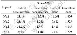
1) The maximum stresses at implant-bone interface. Table 3 shows the maximum von Mises stresses of different structure implants. It can be seen that the interface stresses of implant No.3 are much higher than those of other implants. There is no obvious difference in the maximum stress between implant No.1 and No.4. Implant No.2 has the lowest maximum stress at both cancellous bone and root zone compared with other implants. After the transferring of stress to the surrounding bones, the maximum stress in cortical bone is larger than that of cancellous bone in the surrounding bone tissue. Implant No.1 has the largest stress in cortical bone and No.3 has the largest stress in the root of cancellous bone.
Table 3 Maximum von Mises stresses of implants with different structures
2) Stress distribution at implant-bone interface of implants under static loading. Figure 2 represents the stress distribution at the implant-bone interface in an axial direction. It can be seen that the maximum stresses of implants No. 1, 2 and 4 show no difference in the cortical bone zone and the maximum stress zone is located at the marginal zone of cortical bone. The maximum stress zone of implant No.3 is located at the interface between cortical and cancellous bones. The area of the high stress zone and the value of interface stress of the implant No.2 are the smallest in both the cancellous bone and its root apex.
Figure 3 represents the stress distribution in the cancellous bone zone of the implants. In all cases, there are high stress zones in the junction of the porous layer and the dense body. Among them, implant No.2 has the lowest interface stress. In the cancellous bone zone, the interface stress decreases from top to bottom, and increases at the root apex. And once again, implant No.2 has the lowest stress at the root apex, while implant No.3 has an obvious higher value than the others. The maximum stress exists at the bone interface of the implant No.4, which is 42.96% higher than that of implant No.2.
It is demonstrated that the structure of the implants has a predominate influence on the interface stress. Implant No.3 has a high trend to cause the stress concentration, while implant No.2 can efficiently reduce the interface stress, facilitating the transportation of the interface stress to the surrounding bones, avoiding the stress shielding and concentration, which is beneficial to the long time stability of the implants.
3.2 Effect of elastic modulus on interface stress distribution of implant No.2
It is demonstrated that implant No.2 has the lowest interface stress. Thus, it is chosen to study the effect of elastic modulus of low modulus zone on the interface stress distribution at the interfaces. The elastic modulus in the low modulus zone varies in the range of 80%, 40%, 10% and 1.3% of the modulus of the dense titanium, i.e. 1 370 MPa. Table 4 shows that the interface stress in cancellous bone decreases with the decrease of the modulus of the low modulus layer, while there is no significant change in the cortical bone zone. For the interface stress of surrounding bones, it can be seen that the stress increases and that at the root apex of cancellous bone decreases with the decrease of the modulus of the low modulus layer.
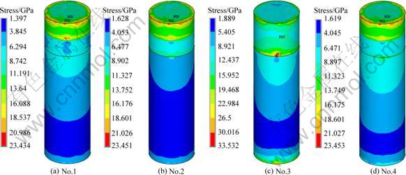
Fig. 2 Stress distribution in axial direction at implant-bone interface of different structure implants
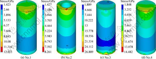
Fig. 3 Stress distribution in spongy bone zone of different structure implants
Table 4 Maximum von Mises stresses of implants
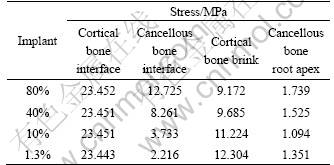
Figure 4 represents the stress distribution at the implant-bone interface in the axial direction. It can be seen that, under the same loading, a decrease of the modulus at low modulus layer has no significant influence on the interface stress of cortical bone. Figure 5 shows the stress distribution at the interface between implant No.2 and cancellous bone. The interface stress varies significantly with the change of the modulus of the low modulus layer. As the modulus of the low modulus layer decreases, the area of the high stress zone reduces, and the volume of the interface decreases dramatically. When the modulus of the low modulus layer reduces to 10% of the dense value, a uniform distribution of the interfacial stress without any high stress zone is obtained. For the specimens with the modulus of 1 370 MPa, the interface stress is 2.216 MPa, 82.6% smaller than that of 80% ones. With the decrease of the modulus, the interface stress between the dense core and the porous layer increases. Figure 6 represents the stress distribution in dense body of implant No.2. It can be seen that the high stress zone is located at the interface between the cortical bone and cancellous bone. For the specimens with the modulus of 10% of the dense ones, the maximum interfacial stress at the porous-dense core interface is 18.556 MPa. And it reduces to 13.752 MPa for 80% specimens.
3.3 Effect of thickness of low modulus zone on interface stress distribution of implant No.2
In order to further optimize the structure of the implant, the effect of thickness of low modulus zone on the interface stress distribution of implant No.2 was carried out, by varying the thickness of the low modulus zone from 0.5, 0.75, 1 to 1.25 mm and maintaining the same implant diameter of 4.1 mm and a constant modulus of low modulus zone, i.e. 1 370 MPa. Figure 7 represents the stress distribution at the implant-bone interface in the axial direction. It can be seen that, in all cases, the cortical bones are in high stress zone while the cancellous bones are in low stress zone. The change of the thickness of low modulus zone affects the stress distribution of cancellous bone a lot while it has little influence on cortical bone, as shown in Fig. 8. With the increase of the thickness, the interface stress decreases, especially in the root apex. Moreover, the distribution of the interface stress becomes more uniform. When it comes to an optimal thickness suitable for the clinical application, the strength and ingrowth of the bone tissues should be considered, which needs further verification of MADIT experiments.
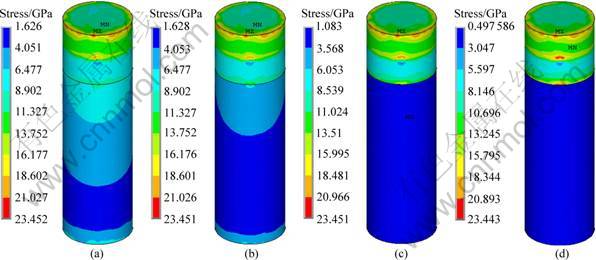
Fig. 4 Stress distribution of implant No.2 in axial direction at implant-bone interface: (a) 80%; (b) 40%; (c) 10%; (d) 1.3%
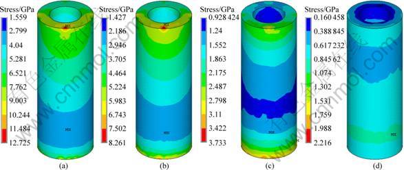
Fig. 5 Stress distribution at interface between implant No.2 and cancellous bone: (a) 80%; (b) 40%; (c) 10%; (d) 1.3%
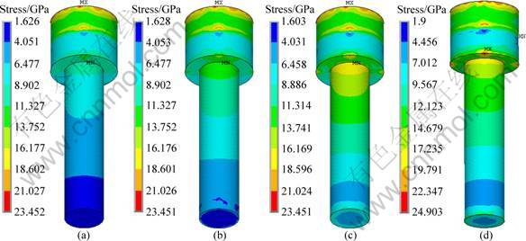
Fig. 6 Stress distribution in dense body of implant No.2: (a) 80%; (b) 40%; (c) 10%; (d) 1.3%
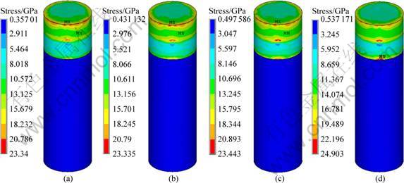
Fig. 7 Stress distribution in axial direction at implant-bone interface of implant No.2 with different thicknesses of low modulus layer: (a) 0.5 mm; (b) 0.75 mm; (c) 1 mm; (d) 1.25 mm
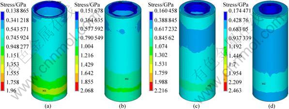
Fig. 8 Stress distribution at cancellous bone interface of implant No.2 with different thicknesses of low modulus layer: (a) 0.5 mm; (b) 0.75 mm; (c) 1 mm; (d) 1.25 mm
4 Discussion
The functions of implant are mainly dependent on the direct bonding with the surrounding bones. The long-term success of an implant is determined by the reliability and stability of the implant bone interface, and the success or failure of an implant is determined by the manner that the stresses at the bone-implant interface transfer to the surrounding bones [1-2]. The main factors contributing to the stability of implants include the structure of the implants, the distribution of the interface stress and the combination mode of the interface. In order to ensure the long-term stability of an implant, the implant should be designed according to two main principles. First, the load should be minimized to avoid exceeding its physiological tolerance as overloading can cause bone resorption or fatigue failure of the implant. On the other hand, underloading may lead to disuse atrophy and subsequent bone loss [3-4]. Second, the contact zone with the bone should be increased to reduce the bone interface stress. The structural characteristic of the mandible shows an outer layer of dense cortical bone and an inner layer of loose cancellous bone. Both the elastic modulus and mechanical strength of cortical bone (10-18 GPa) are higher than those of cancellous bone (1.3-4 GPa). Current dense implants do not have the structure similar to the mandible, as well as modulus. As a result, the mechanical compatibility between the implant and the bone remains unresolved, and the modified active coating on the surface gets easily damaged in the implantation process.
An implant with a low elastic modulus is believed to be beneficial to transferring the stress to the surrounding bones, resulting in a long-term stability [8-9]. The porous implant materials can tremendously improve the implant biocompatibility [10-12] by improving the adhesion and outgrowth of those osteoblasts, promoting the deposition of extracellular matrix, increasing the adsorption of nutrients and oxygen, and promoting the new bones�� growth into pores to achieve biological fixation. The porosity can be changed to adjust the density, strength and elastic modulus of the material to achieve similar mechanical properties to the replaced hard tissues. Meanwhile, the porous structure can provide scaffold for the bioactive coating to promote osseointegration. In this study, according to the structural characteristics of the mandible and the advantages of the porous implant material, an idea of a bio-mimetic implant is proposed. It is a titanium implant composed of a cortical bone zone with a dense structure and a cancellous bone zone with a porous outer layer and a dense body. The cortical bone has a high modulus, and the porous outer layer of the cancellus bone zone has a low modulus. The dense body ensures the strength to meet the requirements of clinical applications. To optimize the structure of the bio-mimetic implants, the finite element analysis was carried out. The effects of implant structure, modulus and thickness of the low modulus layer on the distribution of the interfacial stress were studied.
The interfacial stress of the implants is mainly located at the interface between the implants and the surrounding bones, affecting the interface biological reactions such as bone resorption and remodeling. Cortical bone loss and early implant failure after loading are usually accompanied by the excess stress at the implant bone interface while a low stress may lead to disuse atrophy and subsequent bone loss [13-14]. It is indicated that, under the same situation, the smaller the bone surface area in contact with the implant body is, the greater the overall stress becomes [15]. Cortical bone, which has a higher modulus, higher strength and more resistance to deformation than cancellous bone [16], can bear more loading in masticatory movements [17-20]. In this study, it was supposed that the implant-bone osseointegration was 100%. Under the same loading condition, the stress distributions at the interface of four different structure implants were compared and analyzed, showing that the change of the implant structure and modulus in the cancellous bone had significant effects on the stress distribution. In all cases, there are high stress zone at the interface between cortical and cancellous bone. In cancellous bone, the interface stress decreases from top to bottom, and increases at the root apex.
In the cortical bone zone, all implants present high stress values and the maximum stresses are in the same level. In the cancellous bone zone, the maximum stress of the dense implant interface was 75.58% higher than that of the bio-mimetic implant, and 22.21% higher than that in the root apex zone. The maximum stresses in cancellous bone and root region of implant No.2 are lower than those of other three implants. The maximum stress of implant No.4 is 42.96% higher than that of No.2. Implant No.3 has the highest stresses in root region. The stress distribution at bone-implant interface varied with elastic modulus of low elastic modulus layer. The maximum stresses of implant No.2 decreases with decreasing elastic modulus in cancellous bone region, while there is no significant difference in cortical bone region. When the modulus of the low modulus layer is reduced to 10% of the dense ones, a uniform distribution of interfacial stress without any high stress zone was obtained. With the increase of the thickness of the low modulus layer, the interface stress decreases, especially in the root apex. Moreover, the distribution of the interface stress becomes much uniform.
From the biomechanical point of view, a structure like implant No.2, a modulus matches the cancellous bone and a suitable thickness can effectively reduce the stress in the implant-bone interface and be beneficial to the transfer of interfacial stress to surrounding bones, which is favorable to the long-term stability of the implant. The structural characteristics of this implant are in line with those of the mandible, so that the elastic modulus of the porous zone can be reduced to make the elastic modulus of the implant match with the cancellous bone and thus help the interface stress transferring. The structural characteristics of mandible of implants No.1 and No.4 are ignored, which results in the un-uniform interface stress distribution and stress concentration in cancellous bone. Although implant No.3 has a mandible-like structure, the cancellous bone is a whole low modulus structure, which leads to stress concentration at both interface and root apex.
Implant No.2 has a low modulus-outer and high modulus-interior in the cancellous bone zone. The low modulus-outer can be realized by adjusting the porosity and pore size to match the mechanical properties, especially the elastic modulus, with the surrounding bones. Figure 9 illustrates the stress distribution of the porous and dense implants under vertical loading. In the model, R refers to the radius of the implant, H refers to the height, and F refers to the vertical loading. Assume that the compressive stress and shear stress are uniform, and the compressive stress and shear stress on porous and dense implants are ��1, ��1 and ��2, ��2, respectively. The porous implants provide more contact area with the bone than the dense implants. Assuming that A1 is the added contact area, the equilibrium equations of forces for porous and dense implants can be expressed as:
![]() (1)
(1)
![]() (2)
(2)
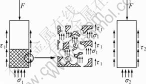
Fig. 9 Stress analysis of implants
Because the compressive strength at the interface is much larger than its shear strength, the value of ��1 similar to ��2, and the added zone A1 are larger, we can obtain ��1<<��2. It means that the shear force of porous implants is much smaller that that of dense ones, which is beneficial for the stability of the low strength cancellous bone.
In current industry, a screw structure is usually adopted to improve the bond strength between the bone and implants. The modulus of screw zone is higher than that of cortical bone, which has a high trend to cause stress shielding and concentration and thus bone absorption [21]. For a porous structure, when the bone tissue grows into the porous structure, the bond strength is improved and the modulus of implants is similar to that of the surrounding bones. No bone absorption occurs under loading because part of the stress can be borne by bone tissues in the pore. In summary, biomimetic style implant No.2, with a high modulus in the cortical bone and low modulus-outer and high modulus-interior in the cancellous bone is superior in the stress transferring. The porous structure can effectively reduce the shear force at the bone-implant interface, providing a suitable environment for bone tissue ingrowth, which is beneficial for the longtime stability of the implants.
5 Conclusions
1) The distribution of interface stress is strongly dependent on the structure of the implants. The bio-mimetic implant No.2 is favorable to transferring the interface stress from the cancellous bone and root apex bone to surrounding bones, avoiding stress shielding and concentration.
2) It is demonstrated that the interface stress varies significantly with the change of the modulus of the low modulus layer. The area of the high stress zone is reduced, and the value of the interface decreases dramatically. When the modulus of the low modulus layer is reduced to 10% of the dense value, a uniform interface stress distribution without any high stress zone was obtained.
3) The change of the thickness of low modulus zone affects the stress distribution of cancellous bone, while it has no significant influence on cortical bone. With the increase of the thickness, the interface stress decreases, especially in the root apex. Moreover, the distribution of the interface stress becomes much uniform.
References
[1] van OSTERWYCK H, DUYCK J, VANDER S, VANDER P G, DECOOMANS M, LIEVEN S, PUERS R, NAERT L. The influence of bone mechanical properties and implant fixation upon bone loading around oral implants [J]. Clin Oral Implants Res, 1998, 9(6): 407-412.
[2] GENG J, TAN K B C, LIU G. Application of finite element analysis in implant dentistry: A review of the literature [J]. J Prosthet Dent, 2001, 85(6): 585-598.
[3] VAILLANCOURT H, PILLAR RM, McCAMMOND D. Factors affecting cortical bone loss with dental implants partially covered with a porous coating: a finite element analysis [J]. Int J Oral Maxillofac Implants, 1996, 11(11): 351-359.
[4] PILLIAR R M, DEPORTER D A, WATSON P A, VALIQUETTE N. Dental implant design effect on bone remodeling [J]. J Biomed Mater Res, 1991, 25(4): 467-483.
[5] BATHE K J. Finite element procedures [M]. Upper Saddle River (NJ): Prentice-Hall; 1996.
[6] SATO Y, WADAMOTO M, TSUGA K, TEIXEIRA E R. The effectiveness of element down sizing on a three-dimensional finite element model of bone trabeculae in implant biomechanics [J]. J Oral Rehabil, 1999, 26: 288-291.
[7] SAHIN S, CEHRELI M C, YALCM E. The influence of functional forces on the biomechanics of implant-supported prostheses��A review [J]. J Dent, 2002, 20: 271-282.
[8] KAYABAS O, YU��ZBASIOG?LU E, ERZINCANLI F. Static, dynamic and fatigue behaviors of dental implant using finite element method [J]. Advances in Engineering Software, 2006, 37(10): 649-658.
[9] MEIJER G J, CUNE M S, VANDOOREN M. A comparative study of flexible (polyactive versus rigid hydroxyapatite) permucosal dental implants��clinical aspects [J]. J Oral Rehabil, 1997, 24(2): 85-88.
[10] St PIERRE J P, GAUTHIER M, LEFEBVRE L P, TABRIZIAN M. Three-dimensional growth of differentiating MC3T3-E1 pre-osteoblasts on porous titanium scaffolds [J]. Biomaterials, 2005, 26(35): 7319-7328.
[11] OTSUKIA B, TAKEMOTOA M, FUJIBAYASHIA S, NEO M, KUKUBO T, NAKAMURA T. Pore throat size and connectivity determine bone and tissue ingrowth into porous implants: Three-dimensional micro-CT based structural analyses of porous bioactive titanium implants [J]. Biomaterials, 2006, 27(35): 5892-5900.
[12] TAKEMOTO M, FUJIBAYASHI S, NEO M, SUZAKI J, KUKUBO T, NAKAMURA T. Mechanical properties and osteoconductivity of��porous bioactive titanium [J]. Biomaterials, 2005, 26(30): 6014-6023.
[13] MISCH C E. Contemporary implant dentistry [M]. 2nd ed. St. Louis: Mosby, 1998.
[14] SCHROEDER A. Oral implantology: basic, ITI hollow cylinder system [M]. New York: Thieme Medical Publishers, 1996: 60-65.
[15] HOLMES D C, LOFTUS J T. Influence of bone quality on stress distribution for endosseous implants [J]. J Oral Implantol, 1997, 23(3): 104-111.
[16] MISCH C E. Density of bone: effect on treatment plans, surgical approach, healing, and progressive bone loading [J]. Int J Oral Implantol, 1990, 6(2): 23-31.
[17] COCHRAN D L. The scientific basis for and clinical experiences with Straumann implants including the ITI dental implant system: A consensus report [J]. Clin Oral Implants Res, 2000, 11(11): 33-58.
[18] LEKHOLM U, ZARB G A. Tissue-integrated prostheses [C]// BRANEMARK P I, ZARB G A, ALBREKTSSON T. Tissue-integrated prostheses. Chicago: Quintessence, 1985: 199-209.
[19] CHEN Liang-jian, LI Yi-min. Influence of structure and elastic modulus of titaniun implant on implant-bone interfacial stress distribution [J]. Journal of Central South University: Science and Technology, 2009, 40(2): 400-405. (in Chinese)
[20] CHEN Liang-jian, GUO xiao-ping, LI Yi-min, LI Ting. Finite element analysis for interfacial stress and fatigue behaviors of bio-mimetic titanium implant under static and dynamic loading conditions [J]. Journal of Central South University: Med Sci, 2010, 35(7): 662-672. (in Chinese)
[21] GEFEN A. computational simulations of stress shielding and bone resorption around existing and computer-designed orthopaedic screws [J]. Medical and Biological Engineering and Computing, 2002, 40(3): 311-322.
��ͬ�ṹ������ֲ��ǽ���Ӧ��������Ԫ����
������1, 2���� ��2��������2���� ͦ2����Сƽ1������1
1. ���ϴ�ѧ ������ҽԺ����ɳ 410013��
2. ���ϴ�ѧ ��ĩұ������ص�ʵ���ң���ɳ410083
ժ Ҫ����Ansys Workbench 10.0����Ԫ�����о���̬��������ֲ��ṹ����ģ�����ģ���ͺ�ȶԹǽ���Ӧ���ֲ���Ӱ�졣��CAD(Pro/E Widefire 2.0)���������Ǻ���ֲ�����ά����Ԫģ�ͣ���������͵���ģ����(1��)��������(2��)�����ʹ�����ģ����(3��)��ȫ������(4��)�������������ֲ��ĽṹӰ��ǽ���Ӧ���ֲ���2����ֲ�������ʹǺ������Ľ������Ӧ������������3�ֽṹ��ֲ��ģ�2����ֲ��ĵ�ģ����ģ���Ľ������������ʹ�������Ӧ����������Χ���ʣ����ӵ�ģ�������ܽ������ʹ�������Ӧ����ʹ����Ӧ���ֲ��������ȡ�������2����ֲ���ڽ���Ӧ����������Χ���ʷ�����������3�ֽṹ��ֲ�塣
�ؼ��ʣ���ֲ�壻����ģ��������Ԫ��������ṹ
(Edited by YANG Hua)
Foundation item: Project (30770576) supported by the National Natural Science Foundation of China; Project (2007AA03Z114) supported by Hi-tech Research and Development Program of China; Project supported by State Key Laboratory of Powder Metallurgy, China
Corresponding author: CHEN Liang-jian; Tel: +86-731-88618554; E-mail: jian007040@sina.com
DOI: 10.1016/S1003-6326(11)60903-5
