

J. Cent. South Univ. (2018) 25: 1240-1250
DOI: https://doi.org/10.1007/s11771-018-3821-9

Application of a combined supporting technology with U-shaped steel support and anchor-grouting to surrounding soft rock reinforcement in roadway
WANG Hui(����)1, 2, ZHENG Peng-qiang(֣��ǿ)1,ZHAO Wen-juan(���ľ�)3, TIAN Hong-ming(�����)4
1. Department of Resource and Civil Engineering, Shandong University of Science and Technology,Tai��an 271000, China;
2. Key Laboratory of Safety and High-efficiency Coal Mining, Ministry of Education,
Anhui University of Science and Technology, Huainan 232001, China;
3. Department of Building Engineering, Taishan Polytecnnic, Tai��an 271019, China;
4. State Key Laboratory of Geomechanics and Geotechnical Engineering, Institute of Rock and Soil Mechanics, Chinese Academy of Science, Wuhan 430071, China
 Central South University Press and Springer-Verlag GmbH Germany, part of Springer Nature 2018
Abstract:
Soft rock surrounding deep roadway has poor stability and long-term rheological effect. More and larger deformation problems of surrounding rock occur due to adverse supporting measures for such roadways, which not only affects the engineering safety critically but also improves the maintenance costs. This paper takes the main rail roadway with severely deformation in China��s Zaoquan coal mine as an example to study the long-term deformation tendency and damage zone by means of in-situ deformation monitoring and acoustic wave testing technique. A three-dimensional finite element model reflecting the engineering geological condition and initial design scheme is established by ABAQUS. Then, on the basis of field monitoring deformation data, the surrounding rock geotechnical and rheological parameters of the roadway are obtained by back analysis. A combined supporting technology with U-shaped steel support and anchor-grouting is proposed for the surrounding soft rock. The numerical simulation of the combined supporting technology and in-situ deformation monitoring results show that the soft rock surrounding the roadway has been held effectively.
Key words:
soft rock roadway; rheological effect; supporting technology; numerical simulation; reinforcement��
Cite this article as:
WANG Hui, ZHENG Peng-qiang, ZHAO Wen-juan, TIAN Hong-ming. Application of a combined supporting technology with U-shaped steel support and anchor-grouting to surrounding soft rock reinforcement in roadway [J]. Journal of Central South University, 2018, 25(5): 1240�C1250.
DOI:https://dx.doi.org/https://doi.org/10.1007/s11771-018-3821-91 Introduction
Demanding for energy with the rapid development of China��s economy is increasing year by year, which makes more and more coal mines begin to exploit deep resource and many roadways have been constructed in more deep strata. Due to the complexity of the geological conditions of deep rock mass, more serious problems to the stability of deep roadway have been happening, especially for the deep soft rock roadway. Large rheological deformation of surrounding rock under high ground pressure leads to serious failure problem, which makes the reinforcement difficulty increase.
In view of the stability problem of deep soft rock roadway, scholars use several ways (such as theoretical analysis, field monitoring and numerical simulation method) to study the mechanical properties, deformation and failure mechanism, supporting method of surrounding rock in deep soft rock roadway. DESAI et al [1], LIU et al [2] and LIAO et al [3] studied the rheological properties of soft rock in theory and derived the mathematical formula between stress, deformation and time to describe the long-term strength characteristics of the soft rock. In-situ monitoring technology was adopted to study the deformation mechanism of soft rock roadway and pointed out that high ground pressure and low strength of surrounding rock are the main factors to result in large deformation of roadway [4�C6]. Meanwhile, numerical simulation (such as FLAC, ABAQUS, UDEC) was used to research the stability of soft rock surrounding deep roadway [7�C10]. And the pertinence supporting measure was put forward to ensure the stability of roadway.
Based on the above existing research results, this paper takes the main rail roadway with severely deformation in China��s Zaoquan coal mine as an example. The in-situ observation, theoretical analysis and numerical simulation are used to study the deformation and failure mechanism of surrounding soft rock. Then, a combined supporting technology is proposed with U-shaped steel support and anchor-grouting to the surrounding soft rock reinforcement. Meanwhile, the effectiveness of the supporting method is validated by numerical simulation and in-situ deformation monitoring.
2 Deformation and failure characteristic of main rail roadway in Zaoquan coal mine
In the range of 7200�C7500 m away from the inlet of the main rail roadway in Zaoquan coal mine, the surrounding rock consists primarily of soft mudstone, while the average buried depth is 620 m, as shown in Figure 1. The cross section shape of the roadway is semi-circle arch, with the net width and height of 4.3 m and 5.4 m, respectively. The supporting measure of the roadway is bolting and concrete spraying. The support parameter of bolts is f20 mm��3500 mm and 9 bolts per section with 3 m intervals are arranged in the roadway, while the depth of concrete is 0.3 m. The section and support system for the roadway are shown in Figure 2. It is badly broken after supproting (about 2 months latter) and the large deformation of surrounding rock is still unable to get control effectively after repeated repair. Surrounding rock distribution of the roadway is shown in Figure 3.
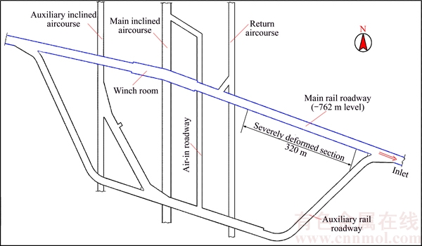
Figure 1 Location and layout of main rail roadway with severely deformed section
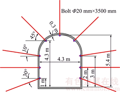
Figure 2 Section and support system for roadway
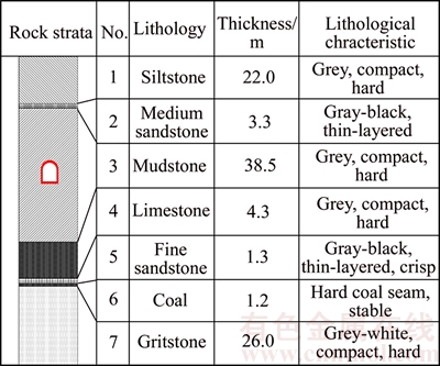
Figure 3 Surrounding rock distribution of roadway
2.1 Deformation and failure characteristics of roadway surrounding rock
Through the deformation monitoring of the section which is about 7300 m from the roadway inlet (as shown in Figure 4), the deformation characteristics of surrounding rock can be described as follows:
1) Long-term deformation. The deformation of surrounding rock is more severe within 20 d after support, and tends to slow subsequently. After supporting for 2 months, the deformation of surrounding rock remains stable. According to the displacement monitoring data (as shown in Figure 4), the deformation of surrounding rock has the typical property of rheology, which can be divided into three stages: severe deformation, slow deformation and steady deformation.
2) Large deformation. The general convergence deformation of roadway is large and the shrinkage of section area can reach to 55% of designed size. After supporting for 2 months, the convergence of roadway sides and arch crown settlement are above 2.2 m and 1.4 m, respectively. Surrounding rock failure form of the roadway is shown in Figure 5.

Figure 4 In-situ measured displacement with time
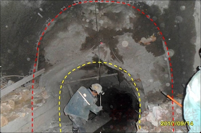
Figure 5 Surrounding rock failure form of roadway (Red line: profile before deformation; Yellow line: profile after deformation)
2.2 Failure scope of surrounding rock
After excavation of underground engineering, the size of failure scope of surrounding rock is an important basis for support [11�C13]. In this paper, acoustic method is used to study the failure scope of surrounding rock.
The ZBL-U510 ultrasonic testing instrument is used in acoustic method. The measuring holes with depth of 10 m are set in the both sidewall and spandrel of roadway. The arrangement of measuring holes and testing instrument is shown in Figure 6. Through the acoustic parameters tests of broken rock mass, failure situation of surrounding rock is analyzed. The test results of different positions of measuring holes using acoustic method are shown in Figure 7. It shows that when the thickness of surrounding rock exceeding 6.4 m and 6.0 m respectively, the wave velocity increases sharply in the positions of 1# and 4# measuring holes, and then tends to be stable gradually. Meanwhile, in the positions of 2# and 3# measuring holes, when the thickness exceeding 6.5 m and 6.2 m respectively, the wave velocity increases sharply, and then tends to be stable. Based on the test results of acoustic method, the failure depth of roadway surrounding rock is about 6.5 m.
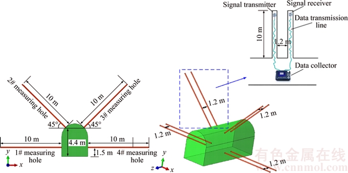
Figure 6 Arrangement of measuring holes and testing instrument
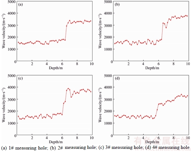
Figure 7 Test results of different positions of measuring holes using acoustic method
3 Mechanical parameter of surrounding rock
3.1 Numerical calculation model
The numerical model is built by the finite element software ABAQUS [14] and the range of 7200�C7500 m away from the inlet of the main rail roadway is selected, where the buried depth is about 620 m. According to the section size and support system of roadway (Figure 2), the numerical model is established as shown in Figure 8. The normal constraints are applied on the left, right and bottom boundary of the model. Based on the previous in-situ monitoring data of ground stress near this site, a vertical stress of 18 MPa is applied on the top surface of the model, while the gravity pressure of rock stratum is applied to the whole model and the lateral pressure coefficient is 0.8. The process of numerical simulation is in accordance with construction scheme on site, which is supporting the surrounding rock with bolts and spraying concrete directly after roadway excavation and then analyzing the deformation and failure state of surrounding rock under rheological effect. The thickness of concrete spraying (lining) is 0.30 m. The mechanical property of bolts is simulated by beam element in ABAQUS.
The yield function used in the model is the Mohr-Coulomb failure criterion, which can be written as follows:
 (1)
(1)
where ��n and ��n are the shear stress and normal stress on the failure plane of rock mass, respectively; C and �� are the cohesion and friction angle.
The location of surrounding rock where the large deformation of the roadway occurs is dominated primarily by soft mudstone, which has the typical property of rheology. Therefore, the stability of the roadway is mainly influenced by the layer of mudstone. Thus, the rheological property is calculated by the empirical formula of creep:
 (2)
(2)
where  and ��i are the creep strain and deviatoric stress in i-direction; P1, P2 and P3 are the undetermined parameters of rock mass; t is the time.
After excavation of roadways, the failure property and long-term rheological effect should be considered simultaneously when analyzing the stress and deformation characteristics of surrounding rock [15�C17]. In this study, the empirical formula of creep (Eqs. (2)) is programmed into the subroutine CREEP in ABAQUS, which is then combined with Mohr-Coulomb failure criterion to simulate the coupling effect of yield failure and rheology impact of rock.
3.2 Back analysis methods for mechanical parameters of surrounding rocks
Based on the field-measured displacements of surrounding rock induced by excavation, the mechanical parameters and coefficient in the creep formula (Eqs. (2)) are analyzed through back analysis methods. In this study, a set of geotechnical parameters selected for back analysis are expressed as follows:
 (3)
(3)
where E and �� are the elastic modulus and Poisson ratio of rock mass; C and �� are the cohesion and friction angle, respectively; P1, P2 and P3 are the undetermined parameters in the empirical formula of creep.
According to the field-measured displacements, the side walls convergence and arch crown settlement can be expressed as and
and respectively.
In the process of numerical simulation for roadway excavation and support, the side walls convergence (u1) and arch crown settlement (u2) are the function of mechanical parameters (X) of surrounding rocks.
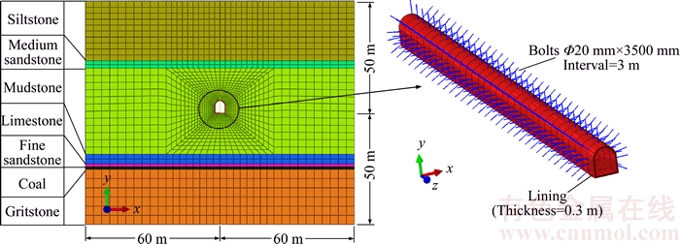
Figure 8 Numerical model
 (4)
(4)
The objective function is often defined as the sum of the absolute errors between numerical and measured displacements [18]. Therefore, the objective function can be expressed as:
 (5)
(5)
During back analysis, the optimization algorithm can minimise the objective function  by changing the parameter values during the iterative process. When tends to be minimum, it can be considered that the parameters obtained from the back analysis are in accordance with the parameters of surrounding rock in-situ.
According to the above ideas, the optimization algorithm is programmed, which is then combined with the FEM calculation of ABAQUS to implement the back analysis for the parameters of surrounding rock.
3.3 Computing results of back analysis
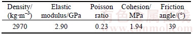
Considering geological investigation data and rock mechanics test report, the mechanical parameters of rock strata and supporting structure in the numerical model are given in Table 1. The large deformation of roadway occurs in the thick mudstone strata with rheological property. Therefore, the main factors influencing the stability of roadway are the mechanical parameters and rheological parameters of mudstone, which would be determined through back analysis.
Figure 4 shows that the deformation of surrounding rock remains stable after supporting for 2 months. Therefore, in this study, the average displacements from 60 d to 80 d after supporting are taken as the ultimate displacements of roadway. According to the monitoring data of deformation, the convergence of roadway sides and arch crown settlement are set to 2.23 m and 1.39 m respectively.
Through back analysis with finite element model, get the values of the convergence of roadway sides and arch crown settlement, which are 2.18 m and 1.42 m respectively. Distribution of displacement after back analysis is shown in Figure 9. Figure 10 shows the failure zone distribution of surrounding rock after back analysis. It can be found that the thickness of the failure zone in surrounding rock is about 6.5 m, which is good consistent with the test results by acoustic method. Therefore, the supporting depth of surrounding rock should exceed 6.5 m.
The back analysis results of mudstone strata��s parameters are shown in Table 2.
4 Proposed supporting strategy
4.1 A combined supporting technology with U-shaped steel support and anchor-grouting
After excavation of roadway, the deformation of surrounding rock occurs due to disturbance. Meanwhile, under high ground stress, the depth of deformation and failure region of soft surrounding rock would increase with time due to rheological effect. Based on the deformation and failure characteristics of the roadway surrounding rock and its failure scope, a combined supporting technology with U-shaped steel support and anchor-grouting is proposed. Detailed construction procedure is as follows:
Table 1 Mechanics parameters of surrounding rock and supporting structure of roadway (�� is back analysis parameter)
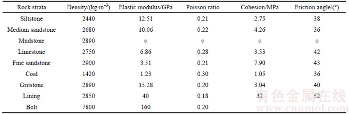
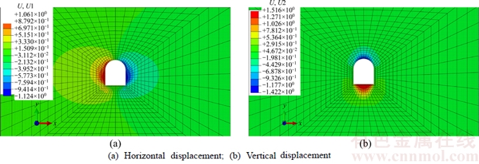
Figure 9 Distribution of displacement after back analysis (Unit: m)
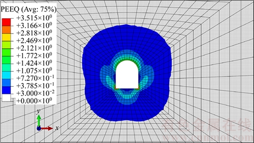
Figure 10 Failure zone distribution of surrounding rock after back analysis
Table 2 Back analysis results of mudstone strata��s parameters

1) After roadway excavation, install #29 yieldable U-steel supports with interval of 3 m. This step can help to prevent the initial deformation of roadway due to excavation.
2) Install grouting cable (f22 mm��7000 mm) in the middle section of two groups of U-steel supports and implement high-pressure grouting. The effect of this procedure contains two aspects. First, the failure region of soft surrounding rock can be strengthened. Second, the grouting reinforcement layer can help to resist the deformation in deep rock mass.
3) Reinforce the floor with prestressed anchor cable to prevent heave. The support parameters are f18.2 mm��12000 mm with interval of 3 m, and the value of applied prestress is 120 kN.
4) Spay concrete with thickness of 0.3 m on the roof and side walls of the roadway.
The grouting cable and prestressed anchor cable support layout is shown in Figure 11.
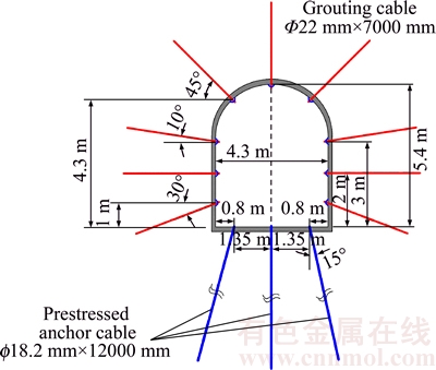
Figure 11 Layout of grouting cable and prestressed anchor cable
4.2 Numerical simulation for combined supporting technology
In order to study the effect of the combined supporting technology, the numerical model is built by ABAQUS to simulate its influence. Mechanics parameters of surrounding rock are shown in Tables 1 and 2. The support function of the grouting reinforcement layer is simulated by increasing the mechanics parameters of this region��s rock mass. Previous study shows that after grouting reinforcement for surrounding rock, its elastic modulus could be increased by more than 30% [18]. Meanwhile, the cohesion and friction angle could be increased by 20%�C30%. According to the analysis of specific conditions in-situ, the mechanics parameters of grouting reinforced region are determined as shown in Table 3.
The support effect of U-steel supports is simulated by beam element in ABAQUS. The yieldable property is simulated by setting the cohesive force of interface between beam elements and rock mass elements. The maximum cohesive force could be set to 200 kN [19]. When the cohesive force exceeds 200 kN, the shrinkage deformation of U-steel supports would happen. In numerical simulation, the density, elastic modulus and Poisson ratio of U-steel supports are set to 7500 kg/m3, 200 GPa and 0.3, respectively.
Table 3 Mechanics parameters of grouting reinforced region
According to the detailed construction procedure of the combined supporting technology with U-shaped steel support and anchor-grouting, numerical simulation includes the following steps:
1) Based on the stress distribution of surrounding rock, the balance of initial ground stress field is carried out for the numerical model.
2) Excavate roadway and install the U-steel supports.
3) Make grouting support for surrounding rock. The thickness of the grouting reinforcement layer is set to 7 m.
4) Install prestressed anchor cables in the floor of the roadway.
5) On the roof and side walls of the roadway, spay concrete with thickness of 0.3 m.
6) Analyze the roadway��s deformation and failure conditions after the rheological deformation of surrounding rock for 150 d.
The numerical model for the combined supporting technology is shown in Figure 12.
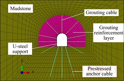
Figure 12 Numerical model for combined supporting technology
Figure 13 shows the numerical simulation results of the combined supporting technology. It can be found that when the roadway has been used for 150 d, the maximum convergence of roadway sides and arch crown settlement are about 31 mm and 14 mm, respectively. In addition, comparing with the numerical simulation results under original support scheme (Figures 9 and 10), the deformation of roadway has been controlled effectively. And the area of failure zone of surrounding rock has decreased significantly.
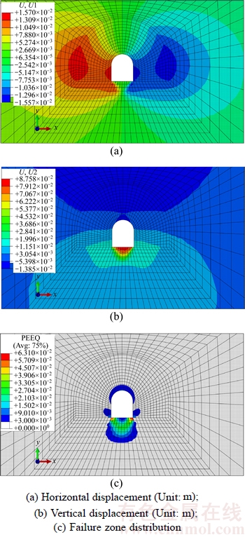
Figure 13 Numerical simulation results of combined supporting technology
The above study shows that the combined supporting technology with U-shaped steel support and anchor-grouting has the protective effect on the stability of roadway, which can control the deformation of the surrounding rock and reduce the failure zone obviously.
4.3 Supporting effect
The combined supporting technology with U-shaped steel support and anchor-grouting has been implemented in the severely deformed roadway region. And measurement stations were installed to monitor the deformation of surrounding rock, which were set to the section of 7300 m (Measurement section 1) and 7400 m (Measurement section 2) from the roadway��s inlet. Based on the observation data of 150 d (Figure 14), the maximum side walls convergence was 34 mm and the maximum arch crown settlement was 18 mm. The displacement speed of the roadway was the fastest in the first 70 d after support, and the deformation speed slowed down afterwards. After supporting for 100 d,the deformation and convergence rates of surrounding rock remained stable. Meanwhile, the numerical simulation result is in good agreement with the monitoring displacement by comparison.
Figure 15 shows the field effect drawing of the combined supporting technology. It can be found that, after support and long-term use of the roadway, its shape and size have no change on the whole and the U-steel support has no sign of bending. Therefore, the surrounding rock of roadway is in good stable state after support.
5 Conclusions
Soft rock surrounding deep roadway has poor stability and long-term rheological effect. More and larger deformation problems of surrounding rock occur due to adverse supporting measures for such roadways. In order to investigate the more efficient measures for the reinforcement, the main rail roadway with severely deformation in China��s Zaoquan coal mine is taken as an example to study a new kind of combined supporting technology with U-shaped steel support and anchor-grouting for the stability of soft rock surrounding deep roadway. A series of conclusions are made as follow:
1) The long-term deformation tendency and failure zone of soft rock surrounding deep roadway are analyzed by in-situ deformation monitoring and acoustic wave testing technique. Then, a three- dimensional finite element model reflecting the engineering geological condition and initial design scheme is established by ABAQUS. Based on the field monitoring deformation data, the surrounding rock geotechnical and rheological parameters of the roadway are obtained by back analysis.
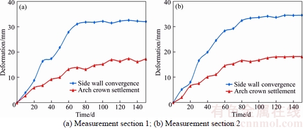
Figure 14 Roadway displacement measurement (Unit: mm)

Figure 15 Field effect drawing of combined supporting technology
2) Based on the deformation and failure characteristics of the roadway surrounding rock and its failure scope, a combined supporting technology with U-shaped steel support and anchor-grouting is proposed. The simulation result shows that the combined supporting technology has the protective effect on the stability of roadway, which can control the deformation of the surrounding rock and reduce the failure zone obviously.
3) The combined supporting technology with U-shaped steel support and anchor-grouting has been implemented in the severely deformed roadway region. The roadway deformation is well controlled with the maximum side walls convergence being 34 mm and the maximum arch crown settlement being 18 mm. Meanwhile, the numerical simulation result is in good agreement with the monitoring displacement. Thus, the combined supporting technology can meet the requirements of stability control for soft rock surrounding deep roadway and could also be used in the similar engineering.
References
[1] DESAI C S, SALAMI M R. Constitutive model and associated testing for soft rock [J]. International Journal of Rock Mechanics & Mining Sciences & Geomechanics Abstracts, 1987, 24(5): 299�C307. DOI: 10.1016/0148- 9062(87)90866-7.
[2] LIU H H, RUTQVIST J, BIRKHOLZER J T. Constitutive relationships for elastic deformation of clay rock: Data analysis [J]. Rock Mechanics and Rock Engineering, 2011, 44(4): 463�C468. DOI: 10.1007/s00603-010-0131-4.
[3] LIAO H J, PU W C, YIN J H, AKAISHI M, TONOSAKI A. Numerical modeling of the strain rate effect on the stress-strain relation for soft rock using a 3-d elastic visco-plastic model [J]. International Journal of Rock Mechanics and Mining Sciences, 2004, 41(Suppl. 1): 1�C6. DOI: 10.1016/j.ijrmms.2004.03.064.
[4] WU L, CUI C, GENG N, WANG J. Remote sensing rock mechanics (RSRM) and associated experimental studies [J]. International Journal of Rock Mechanics and Mining Sciences, 2000, 37(6): 879�C888. DOI: https://doi.org/ 10.1016/S1365-1609(99)00066-0.
[5] SHEN B T. Coal mine roadway stability in soft rock: A case study [J]. Rock Mechanics and Rock Engineering, 2014, 47(6): 2225�C2238. DOI: 10.1007/s00603-013-0528-y.
[6] WANG Hui, CHEN Wei-zhong, WANG Qing-biao, ZHENG Peng-qiang. Rheological properties of surrounding rock in deep hard rock tunnels and its reasonable support form [J]. Journal of Central South University, 2016, 23(4): 898�C905. DOI: 10.1007/s11771-016-3137-6.
[7] KANG Y, LIU Q, GONG G, WANG H. Application of a combined support system to the weak floor reinforcement in deep underground coal mine [J]. International Journal of Rock Mechanics and Mining Sciences, 2014, 71: 143�C150. DOI: 10.1016/j.ijrmms.2014.03.017.
[8] QIAN D, ZHANG N, SHIMADA H, WANG C, SASAOKA T, ZHANG N. Stability of goaf-side entry driving in 800-m-deep island longwall coal face in underground coal mine [J]. Arabian Journal of Geosciences, 2016, 9: 1�C28. DOI: 10.1007/s12517-015-2119-6.
[9] GAO F, STEAD D, KANG H. Numerical simulation of squeezing failure in a coal mine roadway due to mining-induced stresses [J]. Rock Mechanics and Rock Engineering, 2015, 48(4): 1635�C1645. DOI: 10.1007/ s00603-014-0653-2.
[10] SHREEDHARAN S, KULATILAKE P H S W. Discontinuum�Cequivalent continuum analysis of the stability of tunnels in a deep coal mine using the distinct element method [J]. Rock Mechanics and Rock Engineering, 2016, 49(5): 1903�C1922. DOI: 10.1007/s00603-015-0885-9.
[11] WANG F, ZHANG C, WEI S, ZHANG X, GUO S. Whole section anchor�Cgrouting reinforcement technology and its application in underground roadways with loose and fractured surrounding rock [J]. Tunnelling and Underground Space Technology, 2016, 51(1): 133�C143. DOI: 10.1016/ j.tust.2015.10.029.
[12] HAO Y H, AZZAM R. The plastic zones and displacements around underground openings in rock masses containing a fault [J]. Tunnelling and Underground Space Technology, 2005, 20(1): 49�C61. DOI: 10.1016/j.tust.2004.05.003.
[13] WANG H, JIANG Y, XUE S, SHEN B, WANG C, LV J, YANG T. Assessment of excavation damaged zone around roadways under dynamic pressure induced by an active mining process [J]. International Journal of Rock Mechanics and Mining Sciences, 2015, 77: 265�C277. DOI: 10.1016/ j.ijrmms.2015.03.032.
[14] HIBBITT K, KARLSSORN B, SORENSEN P. ABAQUS/standard user subroutines reference manual [M]. USA: The Pennsylvania State University, 2010.
[15] LO K Y, YUEN C M K. Design of tunnel lining in rock for long term time effects [J]. Canadian Geotechnical Journal, 1981, 18(1): 24�C39. DOI: 10.1139/t81-004.
[16] LADANYI B, GILL D E. Design of tunnel linings in a creeping rock [J]. Geotechnical & Geological Engineering, 1988, 6(2): 113�C126. DOI: 10.1007/BF00880802.
[17] MALAN D F. Simulating the time-dependent behaviour of excavations in hard rock [J]. Rock Mechanics and Rock Engineering, 2002, 35(4): 225�C254. DOI: 10.1007/s00603- 002-0026-0.
[18] TIAN H, CHEN W, YANG D, DAI Y, YANG J. Application of the orthogonal design method in geotechnical parameter back analysis for underground structures [J]. Bulletin of Engineering Geology and the Environment, 2016, 75(1): 239�C249. DOI: 10.1007/s10064-015-0730-0.
[19] TIAN H, CHEN W, TAN X, WANG H, TIAN T. Study of reasonable support scheme for soft rock tunnel in high geostress zone [J]. Chinese Journal of Rock Mechanics and Engineering, 2011, 30(11): 2285�C2292. (in Chinese) http://www.rockmech.org/CN/Y2011/V30/I11/2285.
(Edited by YANG Hua)
���ĵ���
�������������ƻ����Ƽ�����֧������
ժҪ�������������Χ�ҳ������������ƻ����⣬���й���Ȫú�������������Ϊ���������ֳ����μ����������Լ����������������Χ�ҳ��ڱ������Ƽ��ƻ���Χ��������ֵģ�ⷽ���������ܹ���ӳ���̵���״������ʼ��Ʒ�������ά����Ԫģ�ͣ������ֳ�����������Ϊ���������ݻ�ȡ���Χ����ѧ������������������Χ���ƻ������������U��֧��+Χ��ê��ע��������֧������������������Ԫģ�Ͷ���֧��Ч��������ֵģ�⣬����ֳ����������ݷ�������֤��֧����������Ч�ԡ�
�ؼ��ʣ��������������ЧӦ��֧����������ֵģ�⣻�ӹ�
Foundation item: Projects(51409154, 41772299) supported by the National Natural Science Foundation of China; Project(J16LG03) supported by the Shandong Province Higher Educational Science and Technology Program, China; Projects(2015JQJH106, 2014TDJH103) supported by the SDUST Research Fund, China; Project(201630576) supported by the Tai��an Scientific and Technologic Development Project, China
Received date: 2016-09-19; Accepted date: 2016-12-08
Corresponding author: WANG Hui, PhD, Associate Professor; Tel: +86-538�C3076036; E-mail: wanghui2004315@163.com; ORCID: 0000-0002-1466-0371
Abstract: Soft rock surrounding deep roadway has poor stability and long-term rheological effect. More and larger deformation problems of surrounding rock occur due to adverse supporting measures for such roadways, which not only affects the engineering safety critically but also improves the maintenance costs. This paper takes the main rail roadway with severely deformation in China��s Zaoquan coal mine as an example to study the long-term deformation tendency and damage zone by means of in-situ deformation monitoring and acoustic wave testing technique. A three-dimensional finite element model reflecting the engineering geological condition and initial design scheme is established by ABAQUS. Then, on the basis of field monitoring deformation data, the surrounding rock geotechnical and rheological parameters of the roadway are obtained by back analysis. A combined supporting technology with U-shaped steel support and anchor-grouting is proposed for the surrounding soft rock. The numerical simulation of the combined supporting technology and in-situ deformation monitoring results show that the soft rock surrounding the roadway has been held effectively.
