

J. Cent. South Univ. (2021) 28: 235-246
DOI: https://doi.org/10.1007/s11771-021-4599-8

Simulation of three-dimensional tension-induced cracks based on cracking potential function-incorporated extended finite element method
WANG Xiang-nan(������)1, YU Peng(����)1, ZHANG Xiang-tao(�����)1,
YU Jia-lin(������)2, HAO Qing-shuo(����˶)1, LI Quan-ming(��ȫ��)3, YU Yu-zhen(������)1
1. State Key Laboratory of Hydroscience and Engineering, Tsinghua University, Beijing 100084, China;
2. China Renewable Energy Engineering Institute, Beijing 100120, China;
3. China Academy of Safety Science and Technology, Beijing 100012, China
 Central South University Press and Springer-Verlag GmbH Germany, part of Springer Nature 2021
Abstract:
In the finite element method, the numerical simulation of three-dimensional crack propagation is relatively rare, and it is often realized by commercial programs. In addition to the geometric complexity, the determination of the cracking direction constitutes a great challenge. In most cases, the local stress state provides the fundamental criterion to judge the presence of cracks and the direction of crack propagation. However, in the case of three-dimensional analysis, the coordination relationship between grid elements due to occurrence of cracks becomes a difficult problem for this method. In this paper, based on the extended finite element method, the stress-related function field is introduced into the calculation domain, and then the boundary value problem of the function is solved. Subsequently, the envelope surface of all propagation directions can be obtained at one time. At last, the possible surface can be selected as the direction of crack development. Based on the aforementioned procedure, such method greatly reduces the programming complexity of tracking the crack propagation. As a suitable method for simulating tension-induced failure, it can simulate multiple cracks simultaneously.
Key words:
Cite this article as:
WANG Xiang-nan, YU Peng, ZHANG Xiang-tao, YU Jia-lin, HAO Qing-shuo, LI Quan-ming, YU Yu-zhen. Simulation of three-dimensional tension-induced cracks based on cracking potential function-incorporated extended finite element method [J]. Journal of Central South University, 2021, 28(1): 235-246.
DOI:https://dx.doi.org/https://doi.org/10.1007/s11771-021-4599-81 Introduction
It has been an extensive focus among researchers using the FEM to intuitively model the occurrence of failures in many scientific and engineering fields [1-7]. As a branch of the FEM, the extended finite element method (XFEM) finds a wide application in describing the cracking problem under a two-dimensional framework, due to its inherent advantage in modelling discontinues field [8-10]. The XFEM modules in the globally matured commercial software provide solutions for simulating a series of three-dimensional cracking problems [11, 12]. However, the three-dimensional calculation is still confronted with several important problems, including the coordination of grids with presence of cracks as well as the continuity and smoothness of the crack propagation direction. The initial method, also as the most frequently employed method at the current time, refers to the secondary modification of the crack surface by means of formula fitting, after calculation of the local crack propagation direction [13-16]. However, such a method involves a highly complicated implementation process, leading to a large amount of programming. Furthermore, the possible accumulating inaccuracy might cause the deviation of simulated crack from the actual propagation direction. Another useful crack simulation method is the particle simulation method, which has been successfully used to simulate random crack initiation and propagation within crustal rocks of the Earth in the field of emerging computational geosciences [17].
OLIVER [18] and CHAVES et al [19] used the embedded discontinuous finite element method to introduce the function field related to the stress in the calculation domain for the tensile failure problem. The subsequent solution of the boundary value of the employed function enabled determination of all envelope surfaces of the propagation direction at one time. Finally, the potential extension surface was selected as the crack propagation direction. PHILIPPE et al [20] introduced the above method into a tool set, which has powerful post-processing ability. Thus, the FEM simulation results of cracks can be displayed very intuitively. Besides, they made a special study on the setting of boundary conditions. PETER et al [21] introduced this method into 2D XFEM program and compared it with other crack tracking algorithms. To further minimize the computational effort, MANZOLI et al [22] restricted the analysis for tracking the discontinuity path to the domain formed by some elements near the crack surface that develops along the loading process. PENG et al [23] referred to such a method as cracking potential function-based crack tracking method, and incorporated it into the FEM-meshless coupling method, eliminating the grid dependency of smeared crack models.
In the current paper, it is considered that the cracking potential function-based crack tracking method (hereafter referred as: cracking potential function method) can play a better role in the framework of XFEM, and to a great extent reduce the programming amount of XFEM in crack tracking. Thus, the aforementioned method is incorporated into our XFEM program, and improves the currently available crack interface contact constitutive model with consideration of three dimensions, to conveniently model the cracking process of three-dimensional entity under complicated conditions. The program has the advantage of simple implementation, accurate prediction of the tension crack surface in terms of position and morphology, preservation of continuity and smoothness of crack surface among grid elements, and reasonable description of the contact relationship of crack interface.
The rest of the paper is organized as follows. Firstly, the primary process of the proposed method is introduced. Secondly, the establishment of the cracking potential function field is demonstrated. Thirdly, the contact constitutive model on the fracture surface is introduced. Lastly, the developed XFEM program with the crack potential function method is applied to the simulation of failure cases of two bending beams and one geotechnical centrifuge model test, as a verification of the proposed method.
2 Method description
2.1 Construction strategy of XFEM
In the XFEM, an additional discontinuous displacement field is superimposed on the traditional FEM method, thus enabling description of discontinuities, such as cracks occurring in rocks or soils.
In the current paper, the displacement field assumes the method proposed by SONG et al [24]:
 (1)
(1)
where �� is the set of all nodes in the calculation domain, N(x) is the shape function, u is the conventional displacement vector, q is the displacement vector of the discontinuous displacement field, and H is Heaviside step function, which can be expressed as:
 (2)
(2)
where f(x) indicates a directed distance function. In the current paper, the positive normal direction of the designated crack surface is specified as the negative direction of f(x), and vice versa.
According to Eq. (2), all nodes in the whole research domain meet 
 (3)
(3)
For elements penetrated by cracks, Eq. (1) can be rewritten as follows.
 (4)
(4)
Thus the element is divided into two virtual elements (Element A and Element B) with virtual nodes as shown in Figure 1, and the following provisions are specified:
 (5)
(5)
where  and
and  are displacement vectors of node I in virtual element A and virtual element B, respectively. Then Eq. (4) can be rewritten as:
 (6)
(6)
where uA(x) and uB(x) correspond to the approximate displacement fields in virtual element A and virtual element B, respectively.
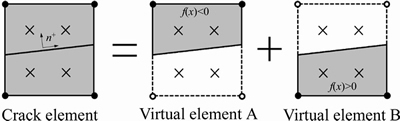
Figure 1 Decomposition diagram of a crack element (Taking the two-dimensional quadrilateral element as an example. Note: hollow node is the virtual node on the virtual element)
It can be seen from Eq. (6) and Figure 1 that the element penetrated by the crack can be regarded as the weighted superposition of two virtual elements, and the weight coefficient is the Heaviside function. The physical meaning of the additional degrees of freedom is the difference between the virtual node displacement and the real node displacement.
This discontinuous displacement field scheme has two advantages: 1) It can use the conventional finite element method to deal with the constraints on the displacement boundary truncated by the cracks; 2) The value of additional degrees of freedom is always 0 on the elements which are not penetrated or stabbed, and these elements can be treated as conventional elements.
2.2 Cracking potential function method
The cracking potential function method aims at the representation of the cracking direction at each position in the whole calculation domain with occurrence of cracking, based on the determined stress field. Supposing the iso-lines of the cracking potential function ��(x) of the calculation domain is the envelopes of the vector field of the cracking direction, the ith equipotential line could be determined by
 (7)
(7)
where Si is the possible cracking path. The crack will propagate along the iso-line of the cracking potential function at the existing crack tip.
As the case of an instantaneous cracking potential function field of a rectangular calculation domain demonstrated in Figure 2, the red solid line indicates the existing crack, which has been extended to the boundary of element A, and the equipotential value of the crack tip is ��4, the program determines the crack propagation based on the criterion whether the tensile stress level of the elements intersected by the equipotential line of ��4 is larger than the threshold value of failure at the current time step. And once the criterion is satisfied, the predicted propagation path coincides with the equipotential line ��4. The method to judge whether the element reaches the failure condition can be set conveniently according to the need. In the current paper, when judging whether the element is cracked or not, it is required to meet at least one of the following two conditions: 1) average the stress of the integral points in the target element, and calculate the corresponding tensile stress level TLaverage, if TLaverage>1, the crack penetrated the element; 2) take the nearest integral point in the target element away from the cracking path, if the tensile stress level of the point TLnearest>1, the crack passes through the element. The reason for this is to consider that the location of crack propagation may be close to the center of the element or just through the corner of the element like elements A and B in Figure 2, respectively.
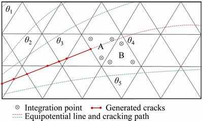
Figure 2 Illustration of crack propagation along equipotential line
The expression of TL is as follows:

 (8)
(8)
where ��3 is the minor principle stress and also a tensile stress, its magnitude in the absolute value may not be small; ft is the tensile strength.
According to Figure 2, several cracks could be simulated simultaneously since each crack corresponds to a varied value of the cracking potential function, facilitating the identification and treatment of each crack.
3 Establishment and solution of cracking potential field
3.1 Establishment of cracking potential field
Assuming the tension-induced cracks occur only along the direction perpendicular to the minor principal stress, the directions of the major, intermediate, and minor principal stresses for a point are indicated by S, T and U, respectively. The latent crack surface is represented by the equipotential line of the determined potential function ��(x), and thus the direction of the minor principal stress indicates the gradient direction of ��(x) as:
 (9)
(9)
According to the inter-perpendicular configuration of each principal stress,
 (10)
(10)
Therefore,
 (11)
(11)
With  Eq. (11) could be written as:
 (12)
(12)
Thus, the following boundary value problem could be derived as:
 (13)
(13)
where q could be considered as a kind of flux; v is the outward unit vector on the flux boundary; ��q is the boundary of the flux; ���� is the boundary of the potential function.
Equation (13) is discretized as:
 (14)
(14)
where ��e(x) is the approximated function; Ni is the shape function of the corresponding node.
Thus the element stiffness matrix of the boundary value problem is determined as:
 (15)
(15)
where`B is the matrix composed of the partial derivative of the shape function.
The matrix D with the rank of 2 possibly contributes to singularity problems, and thus a small perturbation is added to D for a successful solution
 (16)
(16)
where �� is the perturbation factor, which assumes a value of 10-6.
Such procedure is repeated for each element in the computational domain, contributing to the total stiffness matrix:
 (17)
(17)
At last, the boundary value problem is transformed into solution of an algebraic equation set.
 (18)
(18)
During the solution, the boundary of the computational domain involves no flux, and thus specification of the potential function value is needed only for ����. Besides, such a problem is insensitive to constraint values at the boundary, allowing for a flexible configuration of boundary conditions.
3.2 Verification of cracking potential function method in FEM
In order to verify the applicability of the cracking potential function method in the FEM, a cube model is used as a study case for the FEM analysis, with two scenarios.
Scenario 1: the bottom of the cube is fixed and the vertical displacement is imposed on the top surface, and the horizontal displacement of the top surface is constrained, producing a typical drawing problem. Figures 3(a) and (b) offer the direction of the minor principal stress and a set of equipotential surfaces of the cracking potential function, respectively. It indicates that the equipotential surfaces, i.e., the latent crack surfaces under the drawing effect, are all aligned perpendicular to the minor principal stress.
Scenario 2: The direction of the minor principal stress points to the opposite direction of the lower left corner, as shown in Figure 4(a). The corresponding equipotential surfaces presented by Figure 4(b) are a set of spherical surfaces centered right at the lower left corner point.
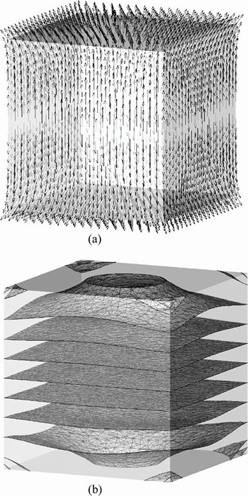
Figure 3 Direction of minor principal stress (a) and equipotential surfaces of cracking potential function (b) for Scenario 1
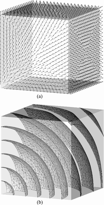
Figure 4 Direction of minor principal stress (a) and equipotential surfaces of cracking potential function (b) for Scenario 2
4 Contact constitutive model and algorithm on crack surface
4.1 Basic description of contact algorithms
The contact problems could be classified into normal and tangential contacts. As a complicated problem with strong nonlinearity at the boundary condition, its solution usually requires iterative algorithm.
The contact constitution D�� on the crack surface could be expressed as
 (19)
(19)
where knn is the normal stiffness on the crack surface, while and
and are the tangential stiffness corresponding to the two orthogonal basic vectors on the crack surface, respectively. The non-diagonal elements manifest the coupling between the normal and tangential stress. Because they contribute to additional complexity of the model and the relevant model parameters frequently make ambiguous physical sense, they are usually ignored in actual application.
4.2 Cohesive crack model under a tension-shear state
Tension-shear state specifies the simultaneous presence of cracking and slippage in crack propagation. The cohesive crack model, based on a simple and clear concept, is frequently employed in cracking under a tension-shear state [25, 26].
If the normal and tangential forces are only related to the normal and tangential slippage, respectively, and the positive direction refers to the compressive stress or inward normal direction, the expressions for normal and tangential stresses at the interface are given by Eqs. (20) and (21), corresponding to Figures 5(a) and (b), respectively.
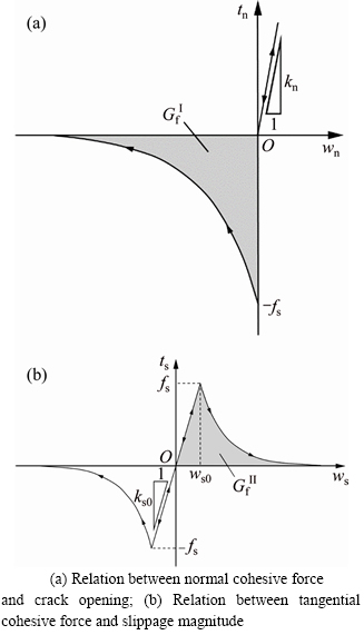
Figure 5 Strain-displacement relation curve of cohesive crack model:
 wn<0 (20)
 (21)
(21)
where tn and ts indicate the normal and tangential stress; wn is the crack opening; ws is the slippage magnitude; ft and fs stand for the tensile strength and shearing strength, respectively; and
and are the normal and tangential cracking energy, respectively; ks0 is the shearing slipping stiffness, and the tangential slippage threshold could be calculated as ws0=fs/ks0.
In three-dimensional calculations, the slippage component w1 and w2 along the two coordinate axes of the local coordinate system are both smaller than the tangential slippage threshold value ws0, but the resultant slippage might exceed the threshold. In such a case, the resultant slippage is used to calculate the derivative of normal and tangential stress with respect to tangential slippage, and subsequently the calculation results are mapped onto the two coordinate axes of the local coordinate system.
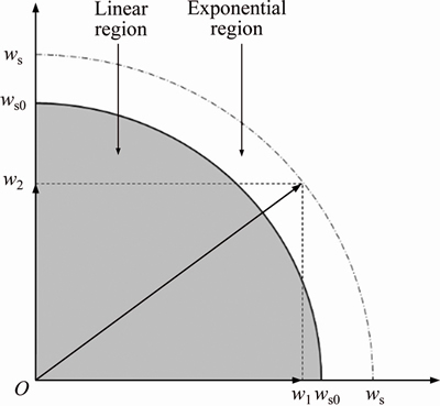
Figure 6 Illustration of tangential slippage in three-dimensional cohesive crack model
5 Study case for verification
5.1 Cracking experiment of three-point bending beam
The current study case only involves numerical calculation process, mainly to examine the validity and credibility of the crack interface contact constitutive model under a three- dimensional framework. The study case shares the same structure, dimension, and loading configuration with the previous studies [27, 28]. The only difference lies in the addition of the third dimension with a thickness of 0.3 mm, covering 3 layers of meshes, as shown in Figure 7. The parameters of the cohesive crack model are the same as those in Ref. [27], including elastic modulus E=100 MPa, Poisson ratio v=0.0, cracking energy Gf=0.1 N/mm and shearing strength ft= 1.0 MPa. The assumption is also involved that the crack would penetrate an element with an average stress larger than the threshold strength.
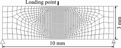
Figure 7 Finite element mesh for three-point bending beam
Figure 8 presents the iso-lines of the cracking potential function at the inception moment of facture formation. Figure 9 demonstrates the ultimate crack of the bending beam after complete development of cracking. Evidently, when the crack criterion is satisfied, the crack in an element will propagate along the direction of the iso-line of the local cracking potential function.
Figure 10 demonstrates the comparison of the load-displacement curve at the loading point between the current calculation and the results from other studies [27, 28] of two dimensions. It indicates that the crack interface contact constitutive model provides a valid and credible prediction.
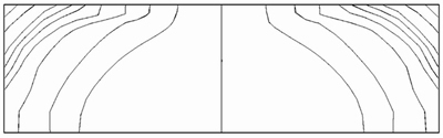
Figure 8 Equipotential lines of cracking potential function
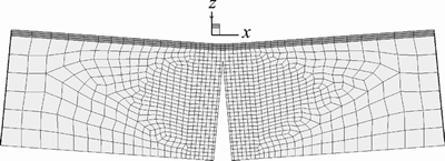
Figure 9 Morphology of bending beam with occurrence of cracking
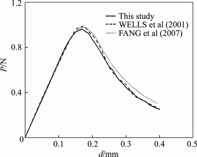
Figure 10 Verification of load-displacement curve for three-point bending beam
5.2 Cracking experiment of four-point bending beam with a single edge notch
ARREA et al [29] proposed a generic four-point bending beam experiment with a single edge notch under the asymmetric loading condition, in order to study the properties of the pure concrete under type I and II complex cracking conditions. Later, BOCCA et al [30] made an extended study to investigate the role of cohesive force between crack surfaces inside concrete during crack propagation. Figure 11 exhibits the shape, dimension and loading condition of an employed specimen. In the experiment, the crack was initiated at the notch, and penetrated the specimen around point A.
The specimen shown in Figure 11 is used as a simulation study case with the XFEM developed by the current paper, and the simulation utilizes a grid with uniform elements. Since the current study case can be regarded as a plane strain problem, in order to reduce grid amount and thus computation resources, the thickness of the beam is chosen as 3 cm instead of the actual 15.6 cm. The employed grid includes 14103 nodes and 62077 tetrahedron elements. The concrete is simplified as ideal elastic material, without consideration of tensile softening. The material properties are tensile strength ft= 2.8 MPa, elastic modulus E=3.5��104 MPa and Poisson ratio v=0.15. The loading assumes force control strategy, with a stepping increment of ��P=10 kN.
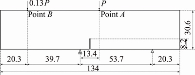
Figure 11 Shape, dimension and loading condition for specimen (Unit: cm)
Due to the assumption of ideal elastic material and the relatively simple loading condition, the direction of the minor principal stress inside the beam exhibits marginal variation during the loading process, contributing to a slight alteration of the cracking equipotential lines based on the minor principal stress. Figure 12 offers the iso-lines of the cracking potential function from calculated results at the end of the first loading stage. Evidently, the crack will propagate along the curved surface to the top loading point once the crack is initiated. Such prediction is consistent with the crack morphology obtained from the experiment by BOCCA et al [30]. Minor discrepancy between the equipotential lines on the front and back surfaces is due to the misalignment of the nodes of the loading elements along the transverse direction.
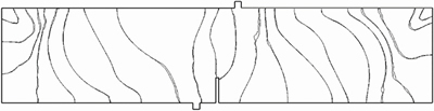
Figure 12 Equipotential lines of cracking potential function
At the loading stage of P=140 kN, the minor principal stress at the notch exceeds the crack threshold, leading to fast crack propagation. Figures 13(a) and (b) illustrate the elements penetrated by the crack propagation.
Figure 14 provides the beam structure with occurrence of crack. Comparing the enlarged local view of the cracked region (Figure 15(a)) and the crack surface obtained from experiment (Figure 15(b)), it can be seen that the cracking propagation trajectory obtained from the crack tracking method is generally coincident with the cracking trajectory in the experiment, essentially independent of the grid configuration. Consequently,the cracking potential function can make our XFEM program have the ability to predict the three- dimensional tension-induced cracks.
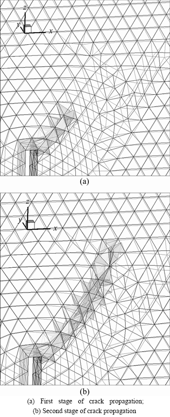
Figure 13 Crack penetrated elements in process of propagation:
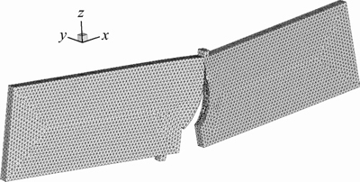
Figure 14 Bending beam morphology with occurrence of cracking
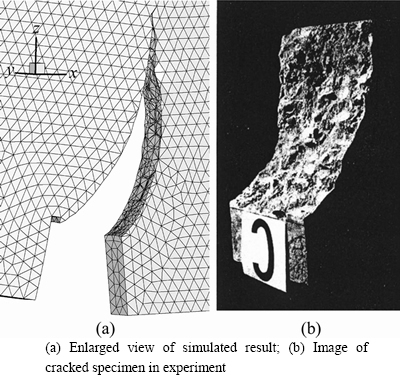
Figure 15 Comparison between numerically simulated crack surface and crack surface in experiment:
5.3 Simulation of transverse cracks in core wall of earth-rockfill dam
Cracking, as the common potential danger of earth-rockfill dam, also belongs to one of the primary failures. ZHANG et al [31] investigated geotechnical centrifuge models with special consideration of the occurrence and propagation mechanism of transverse cracks in the core wall of the earth-rockfill dam. The experiment with Tp0g-t geotechnical centrifuge in Tsinghua University utilizes earth from the core wall of the Nuozhadu core rockfill dam. The experiment includes 3 specimens, and specimen #2 is chosen for the current simulation. The experiment configuration and the experiment model photo are presented in Figures 16 and 17, respectively.
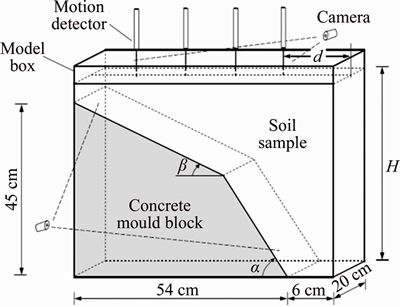
Figure 16 Illustration of configuration of centrifugal model experiment
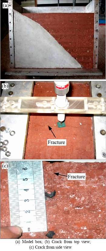
Figure 17 Images of results from the centrifugal model experiment:
The internal dimension of the model box is 600 mm��200 mm��500 mm, with a concrete mould block to simulate the bedrock slope. The loading strategy starts at null centrifugal acceleration, with an increment of 10g for duration of 5 min, and the ultimate loading is 150g for 20 min. The detailed parameters are listed in Table 1.
Three-dimensional simulation is performed with both our XFEM program and the built-in XFEM module in commercial software ABAQUS.
Table 1 Centrifuge model test scheme
The earth properties are specified according to the Duncan-Chang EB model parameters determined by tri-axial experiment, as shown in Table 2. The tensile strength is set as 68 kPa according to the work by ZHANG et al [32].
Table 2 Duncan-Chang EB model parameters of earth
Numerical simulation process:
Step 1: Importing model, and resetting displacement;
Step 2: Implementing 15 stepped loadings with an increment of 10g, and predicting the presence of cracks and subsequent propagation by the program independently.
In order to remove perturbation of secondary cracks, the program allows presence of only one crack.
Table 3 lists the numerical calculation results between the method proposed in the current paper and ABAQUS software.
A close approximation is achieved between the calculation results from our XFEM program and the XFEM modulus in the ABAQUS software, in terms of each considered aspects. The crack appears within a loading interval of 40g-60g, producing an obvious disparity with the geotechnical centrifuge experiment results. A possible reason is that the small-size crack at initiation might be difficult for visual observation. The two programs offer a precise prediction of the crack position, with a simulated crack length bigger than the one in experiment. And the maximum subsidence at top obtained from both simulations are larger than the experimental result. Such discrepancy is likely due to the rebounding and crack healing during dissembling for observation. It also could not be excluded that the constraint in numerical simulation might be to some degree different from the actual experiment.
Figure 18 offers the global view of the crack position obtained from our program, as well as the 5 times enlargement view of the crack region.
6 Conclusions
In this work, the cracking potential function method, which allows for calculation of each latent crack surface, is introduced into our XFEM program, and the interface contact algorithm on the crack surface is improved in three dimensions. Thus, a new method is developed with the ability to model the tension-induced crack propagation under three-dimensional framework. Based on an unambiguous concept, such a method significantly simplifies the implementation of the crack propagation within the grid elements, besides the advantages of precise prediction of cracking direction, the theoretical ability to track several cracks simultaneously, and the enhanced continuity and smoothness of predicted crack surface. By means of two tests of bending beams and one test of the geotechnical centrifuge model, the combination of cracking potential function method with XFEM is confirmed as an alternative for analysis of tension-induced cracking, with prospects worthy for further investigation and development.
Table 3 Comparison among calculation results using two XFEM programs and experimental outcome
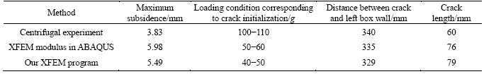
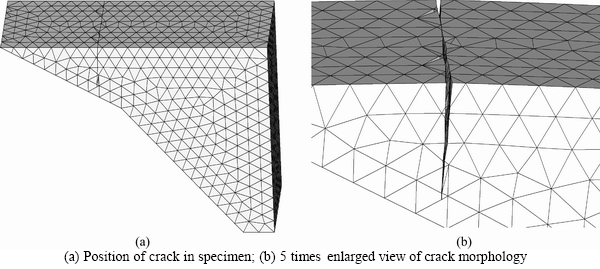
Figure 18 Crack position and morphology calculated using our program:
Contributors
The overarching research goals were developed by LI Quan-ming and YU Yu-zhen. YU Jia-lin provided the study cases. WANG Xiang-nan established the models, completed the program construction and calculated the study cases. YU Peng participated in the programming work and analyzing work. The initial draft of the manuscript was written by WANG Xiang-nan, ZHANG Xiang-tao and HAO Qing-shuo. WANG Xiang-nan, LI Quan-ming, ZHANG Xiang-tao and HAO Qing-shuo replied to reviewers�� comments and revised the final version.
Conflict of interest
WANG Xiang-nan, YU Peng, ZHANG Xiang-tao, YU Jia-lin, HAO Qing-shuo, LI Quan-ming and YU Yu-zhen declare that they have no conflict of interest.
References
[1] TANG Chun-an, YANG Yue-feng. Crack branching mechanism of rock-like quasi-brittle materials under dynamic stress [J]. Journal of Central South University, 2012, 19(11): 3273-3284. DOI: 10.1007/s11771-012-1404-8.
[2] FORMICA G, MILICCHIO F. Crack growth propagation using standard FEM [J]. Engineering Crack Mechanics, 2016, 165: 1-18. DOI: 10.1016/j.engfracmech.2016.08.015.
[3] ZHANG Peng, DU Cheng-bin, ZHANG De-heng. Crack propagation modelling in concrete based on scaled boundary finite element generalized shape function [J]. Journal of Hydraulic Engineering, 2019, 50(12): 1491-1501. DOI: 10.13243/j.cnki.slxb.20190686. (in Chinese)
[4] ZHAO Chong-bin, HOBBS B E, ORD A. Convective and Advective heat transfer in geological systems [M]. Berlin: Springer, 2008. DOI: 10.1016/j.gexplo.2008.11.002.
[5] ZHAO Chong-bin. Dynamic and transient infinite elements: Theory and geophysical, geotechnical and Geoenvironmental Aapplications [M]. Berlin: Springer, 2009. DOI: 10.1007/ 978-3-642-00846-7.
[6] ZHAO Chong-bin. Physical and chemical dissolution front instability in porous media: Theoretical analyses and computational simulations [M]. Berlin: Springer, 2014. DOI: 10.1007/978-3-319-08461-9.
[7] ZHAO Chong-bin, HOBBS B E, ORD A. Finite element modeling of convective pore-fluid flow in fluid-saturated porous rocks within upper crust: An overview [J]. Journal of Central South University, 2019, 26: 501-514. DOI: 10.1007/ s11771-019-4022-x.
[8] DEB D, DAS K C. Extended finite element method for the analysis of discontinuities in rock masses [J]. Geotechnical & Geological Engineering, 2010, 28(5): 643-659. DOI: 10.1007/s10706-010-9323-7.
[9] RU Zhong-liang, ZHAO Hong-bo, YIN Shun-de. Evaluation of mixed-mode stress intensity factors by extended finite element method [J]. Journal of Central South University, 2013, 20(5): 1420-1425. DOI: 10.1007/s11771-013-1630-8.
[10] WANG Xiang-nan, YU Peng, YU Jia-lin, YU Yu-zhen, LV He. Simulated crack and slip plane propagation in soil slopes with embedded discontinuities using XFEM [J]. International Journal of Geomechanics, 2018, 18(12). DOI: 10.1061/ (ASCE)GM.1943-5622.0001290.
[11] VIGNERON L M, VERLY J G, WARFIELD S K. On extended finite element method (XFEM) for modelling of organ deformations associated with surgical cuts [C]// Medical Simulation: International Symposium. Cambridge, MA, USA, 2004. DOI: 10.1007/978-3-540-25968-8_15.
[12] KRSTIC B, RASUO B, TRIFKOVIC D, RADISAVLIEVIC L, RAJIC Z, DINULOVIC M. An investigation of the repetitive failure in an aircraft engine cylinder head [J]. Engineering Failure Analysis, 2013, 34(8): 335-349. DOI: 10.1016/j.engfailanal.2013.08.013.
[13] AREIAS P M A, BELYTSCHKO T. Analysis of three- dimensional crack initiation and propagation using the extended finite element method [J]. International Journal for Numerical Methods in Engineering, 2005, 63(5): 760-788. DOI: 10.1002/nme.1305.
[14] LOEHNERT S, MUELLER-HOEPPE D S, WRIGGERS P. 3D corrected XFEM approach and extension to finite deformation theory [J]. International Journal for Numerical Methods in Engineering, 2011, 86(4, 5): 431-452. DOI: 10.1002/nme.3045.
[15] WANG Zhen, YU Tian-tang, TINH Q B, SATOYUKI T, ZHANG Chuan-zeng, SOHICHI H, JOSE L, CURIEL S. 3-D Local mesh refinement XFEM with variable-node hexahedron elements for extraction of stress intensity factors of straight and curved planar cracks [J]. Computer Methods in Applied Mechanics and Engineering, 2017, 313: 375-405. DOI: 10.1016/j.cma.2016.10.011.
[16] AGATHOS K, CHATZI E, BORDAS S P A. Multiple crack detection in 3D using a stable XFEM and global optimization [J]. Computational Mechanics, 2018, 62: 835-852. DOI: 10.1007/s00466-017-1532-y.
[17] ZHAO Chong-bin, HOBBS B E, ORD A. Fundamentals of computational geoscience: Numerical methods and algorithms [M]. Berlin: Springer, 2009. DOI: 10.1007/ 978-3-540-89743-9.
[18] OLIVER X. On strategies for tracking strong discontinuities in computational failure mechanics [C]// Fifth World Conference on Computational Mechanics. Vienna, Austria, 2002. https://previa.uclm.es/profesorado/evieira/ftp/articulos/ congreso/wccm2_2002.pdf.
[19] CHAVES E W V, OLIVER X. A three-dimensional setting for strong discontinuities modeling in failure mechanics [M]. Monograph CIMNE N-73, 2003. https://www.tdx.cat/handle/ 10803/6861
[20] PHILIPPE J, PAUL S, ELLEN K. Towards the treatment of boundary conditions for global crack path tracking in three-dimensional brittle fracture [J]. Computational Mechanics, 2009, 45(1): 91-107. DOI: 10.1007/s00466-009- 0417-0.
[21] PETER D, GUNTHER M. Crack propagation criteria in the framework of X-FEM-based structural analyses [J]. International Journal for Numerical & Analytical Methods in Geomechanics, 2010, 31(2): 239-259. DOI: 10.1002/nag. 560.
[22] MANZOLI O L, CLARO G K S, RODRIGUES E A, LOPES J. A local-global scheme for tracking crack path in three-dimensional solids [J]. Computers & Concrete, 2013, 12(3): 261-283. DOI: 10.12989/cac.2013.12.3.261.
[23] PENG Chong, WU Wei, ZHANG Bing-yin. Three- dimensional simulations of tensile cracks in geomaterials by coupling meshless and finite element method [J]. International Journal for Numerical & Analytical Methods in Geomechanics, 2015, 39(2): 135-154. DOI: 10.1002/nag. 2298.
[24] SONG J H, AREIAS P M A, BELYTSCHKO T. A method for dynamic crack and shear band propagation with phantom nodes [J]. International Journal for Numerical Methods in Engineering, 2006, 67(6): 868-893. DOI: 10.1002/nme. 1652.
[25] HILLERBORG A, MODEER M, PETERSON P E. Analysis of crack propagation and crack growth in concrete by means of crack mechanics and finite elements [J]. Cement Concrete Research, 1976, 6: 773-782. DOI: 10.1016/0008-8846(76) 90007-7.
[26] PLANAS J, ELICES M, GUNINEA G V, GOMEZ F J, CENDON D A, ARBILLA I. Generalizations and specializations of cohesive crack models [J]. Engineering Crack Mechanics, 2003, 70(14): 1759-1776. DOI: 10.1016/ S0013-7944(03)00123-1.
[27] FANG Xiu-jun, JIN Feng, WANG Jin-ting. Cohesive crack model based on finite element method [J]. Journal of Tsinghua University (Natural Science Edition), 2007, 47(3): 344-347. DOI: 10.16511/j.cnki.qhdxxb.2007.03.010. (in Chinese)
[28] WELLS G N, SLUYS L J. A new method for modelling cohesive cracks using finite elements [J]. International Journal for Numerical Methods in Engineering, 2001, 50: 2667-2682. DOI: 10.1002/nme.143.
[29] ARREA M, INGRAFFEA A R. Mixed-mode crack propagation in mortar and concrete [R]. Ithaca: Department of Structure Engineering, Cornell University, 1982. DOI: http://dx.doi.org/.
[30] BOCCA P, CAPPINTERI A, VALENTE S. Mixed mode fracture of concrete [J]. International Journal of Solids and Structures, 1991, 27(9): 1139-1153.
[31] ZHANG Bing-yin, ZHANG Mei-cong, SUN Xun. Centrifugal modeling of transverse cracking in earth core dams [J]. Geomechanics, 2008, 29(5): 1254-1258. DOI: 10.16285/j.rsm.2008.05.026. (in Chinese)
[32] ZHANG Yan, WANG Jian-guo, ZHANG Bing-yin, LI Quan- ming. Meshless method for numerical simulation of crack propagation in earth dams [J]. Journal of Geotechnical Engineering, 2009, 31(5): 727-731. DOI: 10.3321/j.issn: 1000-4548.2009.05.014. (in Chinese)
(Edited by FANG Jing-hua)
���ĵ���
���ڿ����ƺ�������XFEM��ά�����ѷ�ģ��
ժҪ������Ԫ����У�������ʵ������ά�ѷ���չ����ֵģ���Ϊ�ټ�������������ͨ����ҵ����ʵ�֡������һ�����ԭ���˼����ϵĸ��������⣬���ѷ�����ж���һ���ѵ㡣��������£��ж��ѷ��Ƿ����Լ���չ�ķ������ݵ��Ǿֲ�Ӧ��״̬�����ַ�����Ӧ������ά���ʱ�����Ѵ����ѷ�������֮���Э����ϵ����������չ����Ԫ(XFEM)Ϊ�������ڼ�������������Ӧ����صĺ�������������⺯���ı�ֵ���⣬��һ�����������չ����İ����棬Ȼ�����ѡ�����ܵ���չ����Ϊ�ѷ�Ŀ�չ�������ַ��������������ϴ�̶ȵؽ����������ѷ���չ���ֵı���Ѷȣ������������ƻ����⣬����ͬʱģ��������ơ�
�ؼ��ʣ�XFEM���ѷ죻��ά���㣻�����ƺ����������ƻ�
Foundation item: Project(2017YFC0404802) supported by the National Key R&D Program of China; Projects(U1965206, 51979143) supported by the National Natural Science Foundation of China
Received date: 2020-06-15; Accepted date: 2020-08-13
Corresponding author: LI Quan-ming, PhD, Professor; Tel: +86-15010252576; E-mail: 454968503@qq.com; ORCID: https://orcid.org/ 0000-0001-7751-9976
Abstract: In the finite element method, the numerical simulation of three-dimensional crack propagation is relatively rare, and it is often realized by commercial programs. In addition to the geometric complexity, the determination of the cracking direction constitutes a great challenge. In most cases, the local stress state provides the fundamental criterion to judge the presence of cracks and the direction of crack propagation. However, in the case of three-dimensional analysis, the coordination relationship between grid elements due to occurrence of cracks becomes a difficult problem for this method. In this paper, based on the extended finite element method, the stress-related function field is introduced into the calculation domain, and then the boundary value problem of the function is solved. Subsequently, the envelope surface of all propagation directions can be obtained at one time. At last, the possible surface can be selected as the direction of crack development. Based on the aforementioned procedure, such method greatly reduces the programming complexity of tracking the crack propagation. As a suitable method for simulating tension-induced failure, it can simulate multiple cracks simultaneously.
