

J. Cent. South Univ. (2018) 25: 616-631
DOI: https://doi.org/10.1007/s11771-018-3765-0

An adaptive backstepping sliding mode method for flight attitude of quadrotor UAVs
Jiang Xue-ying(��ѩӨ)1, Su Cheng-li(�ճ���)1, Xu Ya-peng(������)1,Liu Kai(����)1, Shi Hui-yuan(ʩ��Ԫ)1, 2, Li Ping(��ƽ)1, 2
1. School of Information and Control Engineering, Liaoning Shihua University, Fushun 113001, China;
2. School of Automation, Northwestern Polytechnical University, Xi��an, 710072, China
 Central South University Press and Springer-Verlag GmbH Germany, part of Springer Nature 2018
Abstract:
To overcome nonlinear and 6-DOF (degrees of freedom) under-actuated problems for the attitude and position of quadrotor UAVs, an adaptive backstepping sliding mode method for flight attitude of quadrotor UAVs is proposed, in which an adaptive law is designed to online estimate the parameter variations and the upper bound of external disturbances and the assessments is utilized to compensate the backstepping sliding mode control. In addition, the tracking error of the design method is shown to asymptotically converge to zero by using Lyapunov theory. Finally, based on the numerical simulation of quadrotor UAVs using the setting parameters, the results show that the proposed control approach can stabilize the attitude and has hover flight capabilities under the parameter perturbations and external disturbances.
Key words:
quadrotor UAVs; adaptive backstepping sliding mode; adaptive law; tracking error��
Cite this article as:
Jiang Xue-ying, Su Cheng-li, Xu Ya-peng, Liu Kai, Shi Hui-yuan, Li Ping. An adaptive backstepping sliding mode method for flight attitude of quadrotor UAVs [J]. Journal of Central South University, 2018, 25(3): 616�C631.
DOI:https://dx.doi.org/https://doi.org/10.1007/s11771-018-3765-01 Introduction
Recently, with the development of automation technology, computer technology, electronic devices and other high technology, the applications of UAVs (unmanned aerial vehicles) gradually have been extended from the military field to civilian areas. Its popularity has been greatly improved and its application has become increasingly widespread [1�C3]. Quadrotor as UAVs, has got more and more attention of researchers because of its characters with respect to vertical takeoff and landing (VTOL), load-carrying and convenient control [4�C8]. However, quadrotor UAVs is a complex system with under-drive, strong coupling, multivariable, nonlinearity and so on. In addition, it suffers from a variety of physical effects such as gravity and gyroscopic effect. It is also susceptible to be interfered by the external environment such as air flow. Therefore, the accurate and reliable control of the flight attitude is the main difficulty in the present.
At present, the attitude and position control of quadrotor UAVs has been deeply researched by many scholars. A lot of effective control methods, such as PID control [9�C11], adaptive control [12, 13], linear quadratic control (LQR) [14], robust control [15, 16], intelligent fuzzy control [17�C19], nested saturation control [20, 21], model predictive control [22�C24], dynamic inversion control [25], feedback linearization control [26, 27], Lyapunov function design method [28], sliding mode control [29�C34], backestepping technique [35�C40], have been proposed.
BI et al [11] presented an implementation of a hybrid system consisting of a low-cost quadrotor and a small pushcart. The quadrotor was controlled with classical proportional�Cintegral�Cderivative (PID) controller for autonomous visual tracking and landing on the moving carrier. The adopted computer vision algorithms were rather simple, fast and effective under different lighting conditions. Series of experiments showed that the system was easy to deploy and tune, simple and robust, also low-cost. DYDEK et al [5, 6] described the application of direct and indirect model reference adaptive control to a lightweight lowcost quadrotor unmanned aerial vehicle platform. A baseline trajectory tracking controller was augmented by an adaptive controller. The design of the adaptive controller was presented, followed by a comparison of flight test results using the existing linear and augmented adaptive controllers. RINALDI et al [14] applied LQR and neural control theory to control quadrotor UAVs. Comparative tests, showed the more recent and challenging neural networks approach ability to lead to results comparable with the classical theories. SATICI et al [15] presented the design and implementation of an L1-optimal control of a quadrotor unmanned aerial vehicle. With perfect knowledge of plant parameters and no measurement noise, the magnitudes of the errors were shown to exponentially converge to zero. The experimental data showed that the proposed controller rejects persistent disturbances compared with that of a related robust nonlinear controller in the literature, which was quantified by a very small magnitude of the mean error. SANTOS et al [18] described an intelligent system based on fuzzy logic that was developed to control a quadrotor. Simulation results proved the efficiency of this intelligent control strategy. NICOTRA et al [21] addressed the problem of using unmanned aerial vehicles for the transportation of suspended loads. A novel control law capable of steering the aerial robot was introduced to a desired reference while simultaneously limiting the sway of the payload. The stability of the equilibrium was proven rigorously through the application of the nested saturation formalism. ALEXIS et al [22] proposed a switching model predictive attitude controller for an unmanned quadrotor helicopter subject to atmospheric disturbances. The main contribution of the proposed control scheme were the development of a model predictive controller, for the set of the induced linearized piecewise affine models of the system. The result showed the quadrotor rejected the induced wind disturbances while performing accurate attitude tracking. WANG et al [25] presented trajectory tracking control works concerning quadrotor aerial robot with rigid cross structure. A nonlinear dynamic model of the quadrotor was provided, and a controller based on the improved dynamic inverse was synthesized for the purpose of stabilization and trajectory tracking. MOKHTARI et al [26] applied a feedback linearization using Luenberger observer to control the quadrotor UAV. The obtained results showed good convergence of estimated values and satisfying tracking errors of desired trajectories. CHIEW et al [28] proposed a novel approach to address swarm coordination of a multi-agent system consisting of UAVs using robust control Lyapunov function. The approach addressed swarm coordination by commanding each agent to reach a desired separation distance with its neighbors and achieving heading consensus. XU et al [29] proposed a sliding mode control approach to stabilize a class of underactuated systems which were in cascaded form. Two examples of underactuated systems with the sliding mode controller showed that the proposed controller works effectively to stabilize the underactuated systems. XIONG et al [34] mainly solved the position and attitude tracking control for a small quadrotor UAV via discrete-time sliding mode control. The obtained simulation results were promising for the real model of the quadrotor UAV and other complex environments. MADANI et al [35] presented a new control approach for a quadrotor mini-helicopter using the full state backstepping technique. The controller can set the helicopter track three Cartesian position and the yaw angle to their desired trajectories and stabilize the pitch and roll angles by varying the input signals of DC-motors. Various simulations of a quadrotor showed the good performance of the proposed control law. TAN et al [40] designed a tracking controller for a quadrotor to track a moving ground target. This motivated the use of backstepping control on the underactuated quadrotor. The approach proposed used a re-formulated full state cascaded dynamics to eliminate the need for inverse kinematics in a full state backstepping control architecture. It was shown that zero steady state error was achieved in the presence of unmodeled aerodynamics effect and wind disturbance despite no integral action. In addition, a backstepping formulation was derived using contraction theory that guaranteed the boundedness of state response under bounded disturbances such as wind.
In Ref. [41], the kind of backstepping sliding mode control with backstepping design method was proposed. The complicated nonlinear system of quadrotor UAVs was decomposed into the subsystem which was less than the system order, and then the attitude and position control law was computed together with the sliding mode control method. But the backstepping sliding mode control was designed under the condition of the known total uncertain upper bound. However, in UAVs control, the parameter perturbations and upper bound of the external disturbance were usually unknown, which greatly limited the applications of the backstepping sliding mode control.
This work adopts the combination of backstepping sliding mode control and the adaptive control method. An adaptive law is designed through the adaptive control method to online estimate the unknown parameters with respect to the control coefficient matrix and the external disturbance. Then the estimated value is compensated in the backstepping sliding mode control so as to solve the problem of the total uncertain upper bound of the backstepping sliding mode control. Finally, the position and attitude for quadrotor UAVs are implemented mainly using the backstepping sliding mode control. Therefore, this combination overcomes the problem of unknown total uncertain upper bound of quadrotor UAVs. The stability of system is proved through Lyapunov stability theory and Barbalat lemma. The simulation results show that the proposed adaptive backstepping sliding mode controller has a good control performance.
The rest of the paper is organized as follows: Section 2 describes kinetic model of quadrotor UAVs. Section 3 designs the adaptive backstepping sliding mode controller. Section 4 provides the simulation results and analysis. Section 5 presents the experimental verification. Conclusions are presented in Section 6.
2 Kinetic model
For the complex kinetic model, these assumptions based on the bionics principle are as follows:
1) The UAVs is regarded as the rigid body and completely symmetrical. Its mass is unevenly distributed.
2) The center of the mass of UAVs is superposition with the origin of aircraft coordinate frame.
3) It is regarded the earth coordinate frame as inertial coordinate and neglects the curvature and autobiography.
In order to obtain a mathematical model of UAVs, the ground coordinate frame OXYZ and the airframe coordinates oxyz frame firstly are established, as shown in Figure 1. Then the position coordinates �� and attitude coordinate �� are defined where ��=(x, y, z) represents the airframe position vector; ��=(f, ��, ��) are roll angle, pitch angle and yaw angles respectively. The displacement and velocity vector V=(vx, vy, vz) of ground coordinate frame and the rotation angular velocity ��=(p, q, r) have following relationship [42]:
 (1)
(1)
where A(f, ��, ��) is the transformation matrix from the earth coordinate frame to the airframe coordinates; B(f, ��, ��) is the transformation matrix with respect to the rotation for the airframe around the center of the mass. They are as follows:
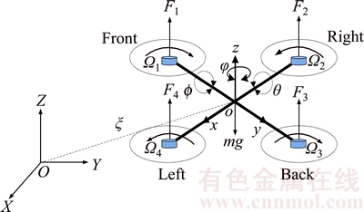
Figure 1 Structure of quadrotor UAVs
 (2)
(2)
 (3)
(3)
where c and s stand for cos and sin functions respectively.
By using Newton��s second theorem and the momentum matrix theorem, Eq. (1) can be derived:
 (4)
(4)
where m is the mass of quadrotor; g is the acceleration of gravity; Fb is the external force for aircraft;  is the moment of inertia.
The control of the position and attitude for quadrotor UAVs is mainly through the changes of F1, F2, F3, F4. Therefore, the input of system is selected as:
 (5)
(5)
The values are expressed as follows:
 (6)
(6)
where ��i (i=1, 2, 3, 4) are the corresponding rotor speed; l is the distance between the center of rotor and the center of mass; d and b are the proportional coefficients.
Synthesizing Eqs. (4)-(6) using Euler�C Lagrange equation, it can obtain as follows:
 (7)
(7)
where Jr is the total moment of inertia for rotor; ��r=��1+��3�C��2�C��4.
The state space vector of plant can be defined as:

The output vector of system is:
 .
.
Letting x1=x,  x3=y,
x3=y,  x5=z,
x5=z, 


 Eq. (7) can be expressed as the state space formation.

 (8)
(8)
The specific values of each parameter are shown as follows:
 ;
;
 ;
;
 ;
;
;
 ;
;
 ;
;
 ;
;
 ;
;
 ;
;
 ;
;
 ;
;
 .
.
3 Adaptive backstepping sliding mode controller design
To overcome the problem of unknown total uncertain upper bound of quadrotor UAVs, the adaptive control method based on backstepping sliding mode control is employed to design an adaptive law. The adaptive method is used to estimate the upper bound of uncertainty in the control system, and the estimated value is compensated to the backstepping sliding mode controller. Then the output of the flight attitude system is computed by the backstepping sliding mode controller. Then the stability of system is proved through Lyapunov stability theory and Barbalat lemma.
3.1 Quadrotor UAVs backstepping sliding mode control
The state space Eq. (8) of quadrotor UAVs is composed of two interconnected subsystems, which can be expressed as follows.
Linear displacement subsystems:
 (9)
(9)
Angle subsystems:
 (10)
(10)
Through analyzing two subsystems, the state variable of the angle subsystem does not include the state variable of the linear displacement subsystem, and its relative position subsystem is independent. The linear displacement subsystems:


include an angular subsystem state variable, which depends on the angle subsystem. The relationship between two subsystems is shown in Figure 2.
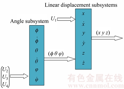
Figure 2 Connection of angle and liner translation subsystems
Due to the independence of angle subsystem, the design idea is presented using angle subsystem controller as an adaptive backstepping sliding mode controller.
The rolling angle f system in Eq. (10) can be expressed as the following form:
 (11)
(11)
where is a nonlinear function; b1=l/Jx; l is the distance between the center of rotor and the center of mass. If the center of rotor and the center of mass does not coincide, it will make b1��0 to avoid the singularity problem of U2.
In practical applications, the perturbation of system parameters and external disturbance should be considered. ��f(x10, x12) and ��b1 are defined as the system parameter perturbation, d7(t) is the external disturbance part. Then the uncertain part is added to the controlled object as follows:
 (12)
(12)
where D7(t) is the total uncertainty of system, which is expressed as 
Roll angle controller U2��s design is based on the Eq.(12) using the backstepping method with the formation of recursion. The sliding mode surface and the adaptive estimation are introduced respectively in the recursive process, thereby achieving good control effect. The design method of adaptive backstepping sliding mode control is generally divided into three steps as follows. Firstly, a virtual control function is constructed by Lyapunov function; Secondly the sliding mode function is designed and the real controller is derived by reaching law; finally, an adaptive law is introduced to estimate the upper bound of the total uncertainty of system, thereby obtaining the adaptive backstepping sliding mode controller U2. The detailed steps are as follows:
Step 1: Because the output of the roll angle system is x7, the output signal of the system is assumed as x7d. Then the tracking error variable z7=x7�Cx7d is defined and its derivative can be obtained.
 (13)
(13)
Define the first step of Lyapunov function:
 (14)
(14)
Taking derivative V1:
 (15)
(15)
Letting  where c7>0, z8=
 c7>0 is the virtual control variable. Then Eq. (15) can be transformed as follows:
 (16)
(16)
In Eq. (16), if z8=0 then  can guarantee the stability of system. But z7z8 is the cross-product term that requires keeping processing in the next step.
Step 2: Define the second step Lyapunov function:
 (17)
(17)
The sliding mode switching function of f roll angle system is defined as:
 (18)
(18)
where k7 must meet Hurwitz condition, i.e. k7>0.
Taking derivative V2, it can be obtained by the combination of Eqs. (14) and (16):


 (19)
(19)
The backstepping sliding mode control law of the roll angle f system is designed:

 (20)
(20)
where  ��7>0.
Substituting Eq. (18) into Eq. (17), it can be obtained as:

 (21)
(21)
Step 3: Because the sliding mode control requires a total uncertainty of the upper bound to meet the requirements of stability and robustness of system, the design of the sliding mode control law is determined by the upper bound of the total uncertainty D7(t). However, in the actual control the parameter perturbation and external disturbance are usually unknown, so that the total uncertainty of the upper bound D7(t) is difficult to determine. Therefore, it is an effective method to estimate the upper bound of the uncertain D7(t) by adding an adaptive law in the backstepping control system.
Define Lyapunov function:
 (22)
(22)
where  is the estimated error, which can be expressed as
 is the estimated value of D7(t) and ��7 is a normal number.
The V3 derivative can be obtained:
 (23)
(23)
In general, the changes of the uncertain parameters and the external disturbance are slow; therefore, it lets 
Then
 (24)
(24)
Substituting Eq. (19) and Eq. (24) into Eq. (23), it can be obtained as:


(25)
The adaptive backstepping control law is designed as follows:
 (26)
(26)
To eliminate the estimation error  in Eq. (25), the adaptive law is designed as follows:
 (27)
(27)
Similarly, the adaptive pitch and yaw angles are:

 (28)
(28)
For linear displacement subsystem in Eq. (10), z-axis backstepping adaptive sliding mode controller is obtained:

 (29)
(29)
 (30)
(30)
where
 (31)
(31)
The adaptive law of the other controllers is represented by Eq. (27):
 (32)
(32)
3.2 Stability analysis
Lemma 1 (Barbalat Lemma [43]): If the function f(x) is continuous under the condition [0, +��] and  has a boundary, then
Substituting Eq. (27) into Eq. (25), the adaptive law is:

 (33)
(33)
where V3 under is monotonically non-increasing function. Because V3(0) is bounded and
 V3(t) is bounded with
  . Thus z7, z8 and are bounded.
Taking the integral V3, it can be obtained as:

 (34)
(34)
Then
 (35)
(35)
Because V3(0) is bounded and V3(t) is decreasing bounded function, it can be obtained:
 (36)
(36)
According to Lemma, it can be inferred as follows:
 (37)
(37)
It means that when
 and
and  asymptotically converge to zero and the output of the roll angle f system in Eq. (12) asymptotically track commands x7d, thereby ensuring the stability of system.
4 Simulation results and analysis
To verify the effectiveness of the proposed method, the proposed adaptive backstepping sliding mode (ABSM) control method is applied in a quadrotor UAVs��s attitude control system compared with the traditional PID control and backstepping sliding mode (BSM) control. Figure 2 shows that the quadrotor UAVs��s attitude angle directly affects its flight position. Therefore two subsystems need to combine in the simulation. However, in order to analyze better results, the simulation results of the attitude subsystem and the position subsystem are separated and compared. The specific physical parameters of purchasing quadrotor UAVs model in the experimental tests are shown in Table 1[44].
Table 1 Physical parameters of quadrotor UAVs

4.1 Posture control simulation
In simulation, assuming the initial attitude of four rotor flight is [4, 5, �C5] rad and the desired attitude is [0, 0, 0] rad.
The parameters of controllers in Eqs. (26) and (28) and, the adaptive laws in Eqs. (27) and (32) are selected as follows:
c7=15, k7=20, h7=80, ��7=10;
c9=10, k9=5, h9=60, ��9=20;
c11=10, k11=15, h11=60, ��11=20.
To better analyze the effect of the external disturbance for quadrotor UAVs, the wind tunnel test in SolidWorks is imitated for quadrotor UAVs fluid dynamics analysis to obtain the parameters of actual flight UAV under the wind disturbance. The specific parameters of the airframe in the fluid analysis are set according to the experimental aircraft model. The speed of four motors is set to 3100 r/min which is measured by the hover status of aircraft model. Then a 2 level wind (wind speed is 3 m/s) disturbance is added through Y-axis along the airframe coordinate frame, as shown in Figure 3.
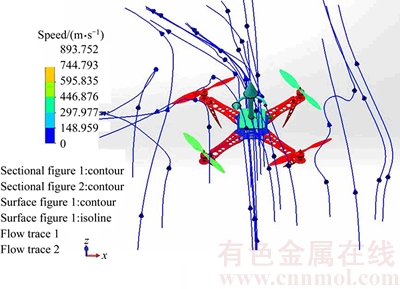
Figure 3 Quadrotor UAVs and flow simulation
The two wind curves from the flow simulation results which pass through the centroid of aircraft are extracted. In curve 2 and curve 9, the data are extracted from the two curves to get the actual static pressure distribution of UAVs surface as follows.
From Figure 4, we can see that the distribution about 2 level wind in the static pressure (it is perpendicular to the direction of the fluid motion) of UAVs surface is a sine wave curve, which are 101325.1895 Pa, 101325.1664 Pa respectively. While the area of UAVs along the y-axis is 4.93��10�C4 m2. Therefore, the maximum wind power for UAVs is 49.95 N. Considering the parameter perturbation of system, the total uncertainty of the attitude angle for controlled object is set:

 .
.
The adaptive backstepping sliding mode control is respectively compared with the traditional PID control and literature [41]. In the compared study, the parameters of PID controller use Z-N tuning method as follows:
kpf=200, kif=500, kdf=30, kp��=100, ki��=200, kd��=20, kp��=60, ki��=150, kd��=10.
The control parameters are selected by the same parameters of the proposed method. The compared results of three control strategies about attitude angle f, �� and �� are shown in Figures 5�C11.
From Figure 5, Figure 7 and Figure 9, we can see that the three methods can achieve a stability control for quadrotor UAVs��s attitude angle. However, the traditional PID has poor control effect and system output is larger overshoot, long convergence time and steady error. Due to variable structure index reaching law relationship for the sliding mode, the control effect of the backstepping sliding mode compared to the traditional PID control has been further improved. The convergence time is greatly shortened and adaptive backstepping sliding mode control at the same time can converge to the desired instruction. However, some deficiencies like the traditional PID control such as a small range of overshoot also exist. In order to further analyze the effect of adaptive backstepping sliding mode control and backstepping sliding mode control, the perspective of the controller input is considered. From Figure 6, Figure 8 and Figure 10, we can see that the backstepping sliding mode control input has the chattering phenomenon, but the proposed method can solve the chattering problem and has a more obvious control effect because an adaptive law can online estimate the perturbation and the upper bound of the external disturbance. From Figure 11 we can see that the three control strategies of attitude angle f, �� and �� are close to the fixed value.
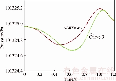
Figure 4 Static pressure curve of barycenter
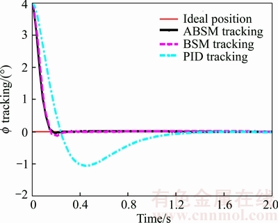
Figure 5 Tracking comparison of roll angle
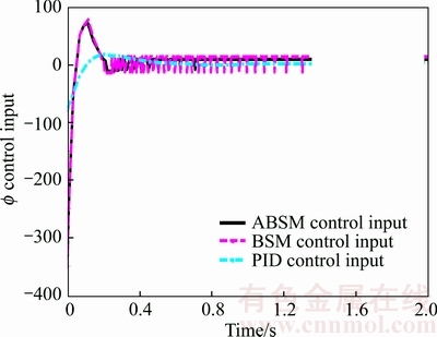
Figure 6 Roll angle control input of three methods
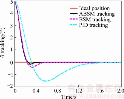
Figure 7 Tracking comparison of pitch angle
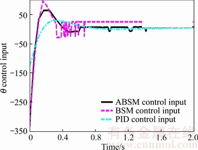
Figure 8 Pitch angle control input of three methods
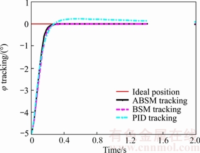
Figure 9 Tracking comparison of yaw angle tracking contrast
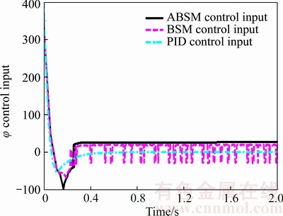
Figure 10 Yaw angle control input of three methods
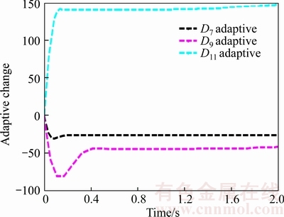
Figure 11 Adaptive change of 


4.2 Position control simulation
In simulation, it assumes that the initial position of quadrotor flight is [0, 0, 0] m and the desired position is [2, 2, 2] m.
Firstly, the initial parameters of the position controller in Eq. (29), Eq. (30) and the adaptive law of Eq. (32) are selected as follows:
c1=15, k1=20, h1=80, ��1=10;
c3=10, k3=5, h3=60, ��3=20;
c5=10, k5=15, h5=60, ��5=20.
The total uncertainty of controlled object is:


 .
.
Then, the parameters of PID controller are adjusted by Z-N tuning method as follows:
kpx=210, kix=400, kdx=20;
kpy=170, kiy=80, kdy=30;
kpz=70, kiz=30, kdz=10.
The compared results of the positions x, y and z with the three control strategies are shown in Figures 12�C18.
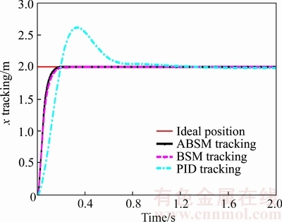
Figure 12 x position tracking contrast
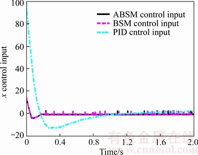
Figure 13 x position control input of three methods
Through the analysis in Figures 12, 14 and 16, the results show that the adaptive backstepping sliding mode control method is adopted to control the position of quadrotor UAVs, which is better control effect than the traditional PID and backstepping because the sliding mode control is not sensitive under the external disturbance and online estimation for the adaptive law of total uncertainty. It will be more responsive to the expectations of the instruction under the smallest error and improve the dynamic and static performance of system. It also further illustrates the advantages of the proposed method.
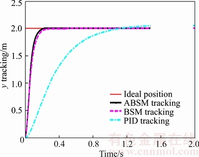
Figure 14 y position tracking contrast
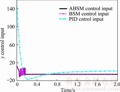
Figure 15 y position control input of three methods
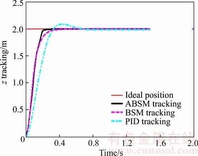
Figure 16 z position tracking contrast
4.3 Robustness test
To study the robustness of the proposed method, taking the roll angle control as an example, the Gauss white noise (noise ratio is 1db) is added in control process compared with the traditional PID control , as shown in Figure 19.
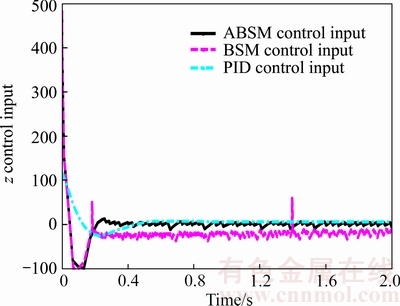
Figure 17 z position control input of three methods
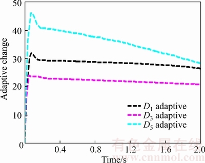
Figure 18 Adaptive change of 


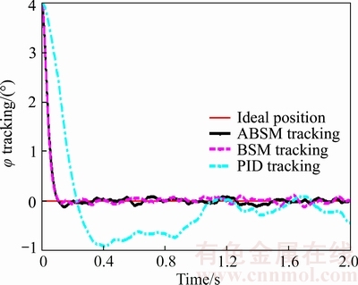
Figure 19 Tracking contrast with white noise
Figure 19 shows that the traditional PID control has bigger fluctuations under the Gaussian white noise and has a big error. However, the proposed method has a small fluctuations and error. It indicates that the control method has strong robustness.
5 Experimental verification
5.1 Experimental platform introduction
To verify the effectiveness of control algorithm, the corresponding experiment platform of quadrotor UAVs��s flight attitude is designed, as shown in Figure 20. Quadrotor UAVs frame is selected as DJI F450. Symmetrical motor wheelbase is 450 mm. The power part uses KV980 brushless motor, which matches 1047 slurry. The total weight of aircraft is about 638 g and its effective load is about 500 g. Inertial navigation sensor uses the six axis motion processing components of MPU6050 module made by InvenSense company, which are integrated 3-axis MEMS gyroscope, 3-axis MEMS accelerometer and a digital motion processor DMP (digital motion processor) hardware accelerating the automatic attitude calculation of engine, thereby reducing the load of motion processing operation for operating system. The sensor can reach 400 kHz fort he highest transmission speed.
The experimental platform is mainly divided into five modules: data acquisition module, which is responsible for data acquisition of the inertial navigation unit; flight control module, which is responsible for data reading and calculation of the inertial unit and the calculated attitude angle is feedbacked to the controller; data communication module using the NRF24L01 wireless communication module, which is mainly responsible for the data transmission of the quadrotor between the main controller and the upper computer, such as the attitude angle information; upper computer control module, which is responsible for the real-time monitoring and the data acquisition of flight attitude in order to further analysize wireless control module, which is mainly responsible for sending the attitude control instruction. The design diagram is shown in Figure 21.
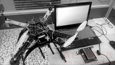
Figure 20 Experimental platform of quadrotor UAVs
5.2 Flight attitude control experiment
This section adopts the compared experimentation for the flight attitude using the traditional PID control algorithm and the adaptive backstepping sliding mode control algorithm. The default control parameters in two methods are selected using the part parameters of the fourth charter. The design control algorithm is programmed by the corresponding control code and is downloaded in the control core. In the experiment,when UAVs reach the stability, the operator remotely switches the control channel for quadrotor UAVs in the high hover. In this time, the flight attitude of quadrotor UAVs is changed by the artificial force. This force is equivalent to uncertain disturbance. The flight effect with the proposed controller is as shown in Figures 22�C24.Figures 25�C27 show the flight effect using the traditional PID controller. From Figure 22, we can see control effect about the attitude angles f, �� and �� with ABSM control. The part of attitude angles is presented in Figure 23. From the two figures,the proposed method has small fluctuations and fast response. The corresponding manipulated variables can be viewed in Figure 24 with smoother fluctuations that help the smooth operation of the whole process. Figure 25 shows the control effect with regard to the attitude angles using PID control. It demonstrates that the attitude angles have big fluctuations and errors. Figure 25 shows the corresponding control variables with PID control. The bigger control variations for the output response are found. Therefore, the proposed method is superior to the traditional PID control.
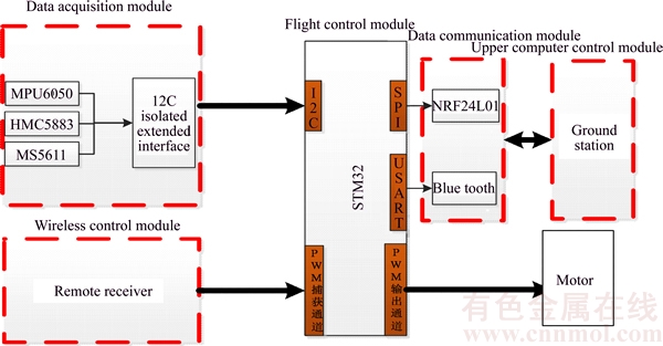
Figure 21 System architecture of quadrotor UAVs
From the experiment for the flight attitude control of quadrotor UAVs, we can see that the roll angle and pitch angle can reach equilibrium in 2 s with external disturbance using the proposed method and the yaw angle reach equilibrium in 4 s. Under the stable status, the roll angle, pitch angle and yaw angle respectively remain about ��0.4��,��0.7��and ��2��. However, the roll angle, pitch angle and yaw angle of quadrotor UAVs reach equilibrium in 6 s using the traditional PID control algorithm. Under the stable status, the roll angle, pitch angle and yaw angle respectively keep within ��0.5��, ��1�� and ��4��. Although the two kinds of control algorithms can enable UAVs attitude to reach stable state, the proposed control algorithm has a faster response speed. Therefore, the attitude angle reaches a steady state in a short time and the control precision of the proposed control algorithm is significantly higher than the traditional PID controller.
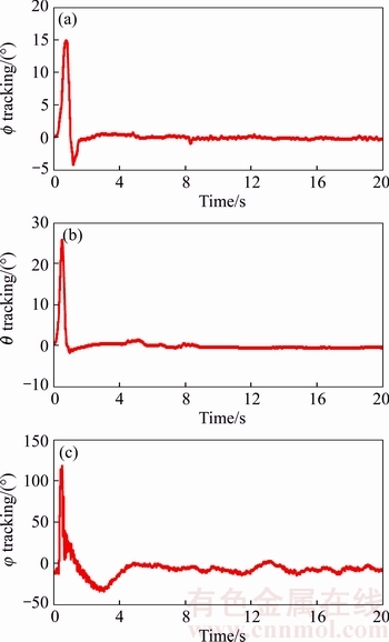
Figure 22 Attitude angles of ABSM control
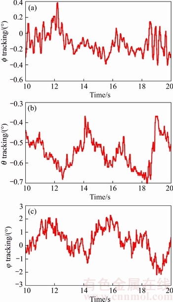
Figure 23 Part of ABSM attitude angles
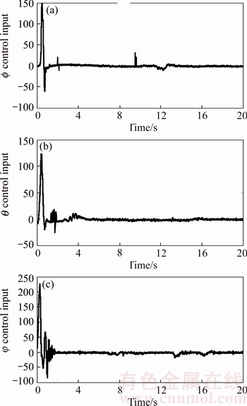
Figure 24 Control input of ABSM
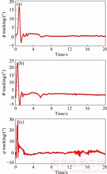
Figure 25 Attitude angles of PID control
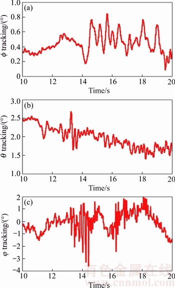
Figure 26 Part of PID attitude angles
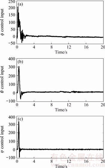
Figure 27 Control input of PID
These results show that the proposed control algorithm can achieve the desired effect and solve the chattering problem by adaptive law.
6 Conclusions
The flight attitude for quadrotor UAV is easy to be affected by the nonlinearity and strong coupling, external disturbance, parameter perturbation and other uncertain factors. This paper proposes an adaptive backstepping sliding mode control algorithm. The stability of control system is proved by Lyapunov theory. The adaptive method is used to estimate the upper bound of uncertainty in the control system, and the estimated value is compensated to the backstepping sliding mode controller. Then the output of the flight attitude system is computed by the backstepping sliding mode controller. The controller has simple structure and excellent tracking performance. The simulation results show that the proposed method has fast response, small tracking error and strong robustness.
References
[1] Kurnaz S, Cetin O, Kaynak O. Fuzzy logic based approach to design of flight control and navigation tasks for autonomous unmanned aerial vehicles [J]. Journal of Intelligent & Robotic Systems, 2009, 54(1�C3): 229-244.
[2] Ryll M, Bulthoff H H, Giordano P R. Modeling and control of a quadrotor UAV with tilting propellers [C]// 2012 IEEE International Conference on Robotics and Automation (ICRA). RiverCentre, Saint Paul, Minnesota, USA: IEEE, 2012: 4606-4613.
[3] Gupte S, Mohandas P I T, Conrad J M. A survey of quadrotor unmanned aerial vehicles [C]// Southeastcon, 2012 Proceedings of IEEE. Orlando, FL, USA: IEEE, 2012: 1-6.
[4] Ng T T H, Leng G S B. Design of small-scale quadrotor unmanned air vehicles using genetic algorithms [J]. Proceedings of the Institution of Mechanical Engineers Part G, Journal of Aerospace Engineering, 2007, 221(5): 893-905.
[5] Dydek Z T, Annaswamy A M, Lavretsky E. Adaptive control of quadrotor UAVs in the presence of Actuator Uncertainties [C]// AIAA Infotech@aerospace. Atlanta, Georgia: AIAA, 2010: 1�C9.
[6] Dydek Z T, Annaswamy A M, Lavretsky E. Adaptive control of quadrotor UAVs: A design trade study with flight evaluations [J]. IEEE Transactions on Control Systems Technology, 2013, 21(4): 1400-1406.
[7] Bolandi H, Rezaei M, Mohsenipour R, Nemati H��Smailzadeh S M. Attitude control of a quadrotor with optimized PID controller [J]. Intelligent Control & Automation, 2013, 4(3): 342-349.
[8] Xian Bin, Zhao Bo, Zhang Yao, Zhang Xu. A low-cost hardware-in-the-loop-simulation testbed of quadrotor UAV and implementation of nonlinear control schemes [J]. Robotica, 2015, 1: 1-25.
[9] Efe M  . Neural network sssisted computationally simple
  control of a quadrotor UAV [J]. IEEE Transactions on Industrial Informatics, 2011, 7(2): 354-361.
[10] Lim H, Park J, Lee D, Kim H J. Build your own quadrotor: Open-source projects on unmanned aerial vehicles [J]. IEEE Robotics & Automation Magazine, 2012, 19(3): 33-45.
[11] Bi Ying-kai, Duan Hai-bin. Implementation of autonomous visual tracking and landing for a low-cost quadrotor [J]. Optik�� International Journal for Light and Electron Optics, 2013, 124(18): 3296-3300.
[12] Islam S, Liu P X, Saddik A E. Nonlinear adaptive control for quadrotor flying vehicle [J]. Nonlinear Dynamics, 2014, 78(1): 117-133.
[13] ZHAO S T, GAO X W. Robust adaptive control for a class of uncertain non-affine nonlinear systems using neural state feedback compensation [J]. Journal of Central South University, 2016, 23(3): 636�C643.
[14] Rinaldi F, Chiesa S, Quagliotti F. Linear quadratic control for quadrotors UAVs dynamics and formation fight [J]. Journal of Intelligent & Robotic Systems, 2013, 70(1�C4): 203-220.
[15] Satici A C, Poonawala H, Spong M W. Robust optimal control of quadrotor UAVs [J]. Access IEEE, 2013, 1: 79-93.
[16] Ryan T, Kim H J. LMI-based gain synthesis for simple robust quadrotor control [J]. IEEE Transactions on Automation Science & Engineering, 2013, 10(4): 1173-1178.
[17] Jurado F, Castillo-TOLEDO B, GENNARO S D. Stabilization of a quadrotor via Takagi-Sugeno fuzzy control [C]// The 12th World Multi-Conference on Systemics, Cybernetics and Informatics. 2008: 1�C6.
[18] Santos M, L��pez V, Morata F. Intelligent fuzzy controller of a quadrotor [C]// 2010 International Conference on Intelligent Systems and Knowledge Engineering (ISKE). Hangzhou, China: IEEE, 2010: 141-146.
[19] Johnson M D, Ayoubi M A. Shared fuzzy control of multiple quadrotor UAVs with time-dependent delay and bounded control-input constraint [C]// Proceedings of ASME 2015 Dynamic Systems and Control Conference. Columbus, Ohio, USA: ASME, 2015: 1�C10.
[20] Castillo P, Lozano R, Dzul A E. Modelling and Control of Mini-Flying Machines [M]. London: Springer Publishing Company, Incorporated, 2005.
[21] Nicotra M M, Garone E, Naldi R, Marconi L. Nested saturation control of an UAV carrying a suspended load [C]// 2014 American Control Conference (ACC). Portland, Oregon, USA: IEEE, 2014: 3585-3590.
[22] Alexis K, Nikolakopoulos G, Tzes A. Model predictive quadrotor control: attitude, altitude and position experimental studies [J]. Iet Control Theory & Applications, 2012, 6(12): 1812-1827.
[23] Sadeghzadeh I, Abdolhosseini M, ZHANG You-min. Payload drop application using an unmanned quadrotor helicopter based on gain-scheduled PID and model predictive control [J]. Unmanned Systems, 2012, 2(1): 386-395.
[24] Shi Hui-yuan, Su Cheng-li, Cao Jiang-tao, LI Ping, SONG Ying-li, LI Ning-bo. Incremental multivariable predictive functional control and its application in a gas fractionation unit [J]. Journal of Central South University, 2015, 22(12): 4653�C4668.
[25] Wang Li-feng, He Yi-chong, Zhang Zhi-xiang, He Cong-kui. Trajectory tracking of quadrotor aerial robot using improved dynamic inversion method [J]. Intelligent Control & Automation, 2013, 4(4): 343-348.
[26] Mokhtari A, M'Sirdi N K, Meghriche K, Belaidi A. Feedback linearization and linear observer for a quadrotor unmanned aerial vehicle [J]. Advanced Robotics the International Journal of the Robotics Society of Japan, 2006, 20(1): 71-91.
[27] Choi I H, Bang H C. Quadrotor-tracking controller design using adaptive dynamic feedback-linearization method [J]. Proceedings of the Institution of Mechanical Engineers Part G, Journal of Aerospace Engineering, 2014, 228(12): 2329-2342.
[28] Chiew S H, Zhao W H, Go T H. Swarming coordination with robust control Lyapunov function approach [J]. Journal of Intelligent & Robotic Systems, 2013, 78(3, 4): 499-515.
[29] Xu Rong, zg��ner U. Sliding mode control of a class of underactuated systems [J]. Automatica, 2008, 44(1): 233-241.
[30] Lee D, Kim H J, SASTRY S. Feedback linearization vs. adaptive sliding mode control for a quadrotor helicopter [J]. International Journal of Control Automation & Systems, 2009, 7(3): 419-428.
[31] Sharifi F, Mirzaei M, Gordon B W, ZHANG You-min. Fault tolerant control of a quadrotor UAV using sliding mode control [C]// 2010 Conference on Control and Fault Tolerant Systems Nice. France: IEEE, 2010: 239-244.
[32] Efe M. Battery power loss compensated fractional order sliding mode control of a quadrotor UAV [J]. Asian Journal of Control, 2012, 14(2): 413-425.
[33] Zheng En-hai, Xiong Jing-jing, Luo Ji-liang. Second order sliding mode control for a quadrotor UAV [J]. ISA Transactions, 2014, 53(4): 1350-1356.
[34] Xiong Jing-jing, Zhang Guo-bo. Discrete timeslidingmodecontrolforaquadrotorUAV [J]. Optik�� International Journal for Light and Electron Optics,2016, 127(8): 3718-3722.
[35] Madani T, Benallegue A. Control of a quadrotor mini-helicopter via full state backstepping technique [C]// Proceedings of the IEEE Conference on Decision and Control. San Diego, CA, USA, 2006: 1515-1520.
[36] Pollini L. Simulation and robust backstepping control of a quadrotor aircraft [C]// AIAA Modeling and Simulation Technologies Conference and Exhibit. Honolulu, Hawall, 2008: 1�C18.
[37] Saif A A, Dhaifullah M, Al-Malki M, Shafie M E. Modified backstepping control of quadrotor [C]// 2012 9th International Multi-Conference on Systems, Signals and Devices (SSD). Chemnitz: IEEE, 2012: 1-6.
[38] Lee D, Ha Chang-su, ZUO Zhi-yuan. Backstepping control of quadrotor-type UAVs and its application to teleoperation over the Internet [M]// Intelligent Autonomous Systems 12. Springer Berlin Heidelberg, 2013: 217-225.
[39] Ha Chang-su, ZUO Zhi-yuan, Choi B F, Lee D. Passivity- based adaptive backstepping control of quadrotor-type UAVs [J]. Robotics & Autonomous Systems, 2014, 62(9): 1305- 1315.
[40] Tan C K, Wang Jian-liang, Paw Y C, Ng T Y. Tracking of a moving ground target by a quadrotor using a backstepping approach based on a full state cascaded dynamics [J]. Applied Soft Computing, 2016, 47(10): 47-62.
[41] Gong Xun, BAI Yue, Hou Zhi-cheng, ZHAO Chang-jun, TIAN Yan-tao, SUN Qiang. Backstepping sliding mode tracking control of Quad rotor under input saturation [J]. International Journal of Intelligent Computing & Cybernetics, 2012, 5(4): 515-532.
[42] nadda s, swarup a. Development of backstepping based sliding mode control for a quadrotor [C]// 2014 IEEE 10th International Colloquium on Signal Processing & its Applications (CSPA). IEEE: Kuala Lumpur, Malaysia, 2014: 10-13.
[43] Min Ying-ying, Liu Yun-gang. Barbalat lemma and its application in analysis of system stability [J]. Journal of Shandong University, 2007, 37(1): 51-50. (in Chinese)
[44] Bouabdallah S, Siegwart R. Backstepping and sliding-mode techniques applied to an indoor micro quadrotor [C]// Proceedings of the 2005 IEEE International Conference of Robotics and Automation. IEEE: Barcelona, Spain, 2005: 2247�C2252.
(Edited by HE Yun-bin)
���ĵ���
���������˻�������̬������Ӧ���ݻ�ģ����
ժҪ������������������˻�������̬ϵͳ�ķ�����ǿ��ϡ������ż������㶯�ȸ��ֲ�ȷ������Ӱ�죬���һ������Ӧ���ݻ�ģ�����㷨������������ŵ������֤������ϵͳ���ȶ��ԡ���������Ӧ���������Կ���ϵͳ�в�ȷ�����Ͻ�������߹��ƣ���������ֵ���������ݻ�ģ�����У�Ȼ���ɷ��ݻ�ģ����ʵ�ַ�����̬ϵͳ����������������漰ʵ�����������÷�������Ӧ�ٶȿ죬�������С�������нϺõ�³���ԡ�
�ؼ��ʣ����������˻�������Ӧ���ݻ�ģ���ƣ�����Ӧ�ɣ��������
Foundation item: Project(61203021) supported by the National Natural Science Foundation of China; Project(2011216011) supported by the Scientific and Technological Project of Liaoning Province, China; Project(2013020024) supported by the Natural Science Foundation of Liaoning Province, China; Projects(LJQ2015061, LR2015034) supported by the Program for Liaoning Excellent Talents in University, China
Received date: 2016-06-25; Accepted date: 2017-12-20
Corresponding author: SU Cheng-li, PhD, Professor; Tel: +86-24-56860749; E-mail: sclwind@sina.com; SHI Hui-yuan, PhD, Experimentalist; E-mail: shy723915@126.com; ORCID: 0000-0001-7483-968x
Abstract: To overcome nonlinear and 6-DOF (degrees of freedom) under-actuated problems for the attitude and position of quadrotor UAVs, an adaptive backstepping sliding mode method for flight attitude of quadrotor UAVs is proposed, in which an adaptive law is designed to online estimate the parameter variations and the upper bound of external disturbances and the assessments is utilized to compensate the backstepping sliding mode control. In addition, the tracking error of the design method is shown to asymptotically converge to zero by using Lyapunov theory. Finally, based on the numerical simulation of quadrotor UAVs using the setting parameters, the results show that the proposed control approach can stabilize the attitude and has hover flight capabilities under the parameter perturbations and external disturbances.
