
J. Cent. South Univ. Technol. (2011) 18: 909-916
DOI: 10.1007/s11771-011-0780-9![]()
Three-dimensional finite element analysis on effects of tunnel construction on nearby pile foundation
YANG Min(����)1, 2, SUN Qing(����)1, 2, LI Wei-chao(������)3, MA Kang(����)4
1. Key Laboratory of Geotechnical and Underground Engineering of Ministry of Education,
Tongji University, Shanghai 200092, China;
2. Department of Geotechnical Engineering, Tongji University, Shanghai 200092, China;
3. School of Architecture, Landscape and Civil Engineering, University College Dublin, Ireland;
4. Department of Civil Engineering, Xiamen University, Xiamen 361005, China
? Central South University Press and Springer-Verlag Berlin Heidelberg 2011
Abstract:
A three-dimensional finite element simulation was carried out to investigate the effects of tunnel construction on nearby pile foundation. The displacement controlled model (DCM) was used to simulate the tunneling-induced volume loss effects. The numerical model was verified based on the results of a centrifuge test and a set of parametric studies was implemented based on this model. There is good agreement between the trend of the results of the centrifuge test and the present model. The results of parametric studies show that the tunnelling-induced pile internal force and deformation depend mainly on the pile-tunnel distance, the pile length to tunnel depth ratio and the volume loss. Two different zones are separated by a 45�� line projected from the tunnel springline. Within the zone of influence, the pile is subjected to tensile force and large settlement; whereas outside the zone of influence, dragload and small settlement are induced. It is also established that the impact of tunnelling on a pile group is substantially smaller as compared with a single pile in the same location with the rear pile in a group, demonstrating a positive pile group effect.
Key words:
1 Introduction
Scarcity of land and rapid increasing population have led to frequent exploitation of underground space in dense urban areas. Unfortunately, many structures exist long before the tunnels are planned. Thus, it is increasingly complex and challenging technically to build underground tunnels which almost inevitably run close to the piles supporting the existing buildings. Research on the effects of tunnel construction on nearby pile foundation began with the laboratory investigation performed by MORTON and KING [1]. Since then, the number of researchers carrying out such study has tremendously increased. Some centrifuge model tests have emerged (HEGARDEN et al [2]; LOGANATHAN et al [3]; JACOBSZ et al [4]; ONG et al [5]) and revealed that significant lateral and vertical forces could be induced on piles due to nearby tunnel excavations. A two-stage approach to study the tunnelling-induced pile response is used (BROMS and PANDEY [6]; CHEN et al [7]; KITIYODOM et al [8]; SURJADINATA et al [9]). The finite element analyses by LEE et al [10], MROUEH and SHAHROUR [11], LEE et al [12], ONG et al [13] and CHENG et al [14] have provided valuable insight and understanding into the various factors that affect the tunnelling-induced performance of pile foundations.
In the present study, for further understanding of the tunnel-pile interaction problem, tunnelling-induced piles responses are proposed to study by a three-dimensional finite element modelling using H-S (Hardening-Soil) constitutive model for the soil behaviour. The first part of the paper presents the details of the numerical model used in this study. The model has been verified by back analysis of centrifuge tests carried out by ONG. The second part presents the results of parametric studies for single pile responses due to tunnelling. The influences of the following parameters are assessed: pile-tunnel distance (Xpile), pile length to tunnel depth ratio (Lp/Htun) and volume loss (VL). This provides an insight into the significance of each parameter to the analysis of pile responses due to tunnelling. Lastly, the results of pile group study are presented.
2 Numerical modelling
Figure 1 shows the relative location of tunnel and pile. The Hardening-Soil model was used in finite element analysis. The Hardening-Soil model is an advanced model for simulating the behavior of different types of soil, both soft soils and stiff soils (SCHANZ, 1998). When subjected to primary deviatoric loading, soil shows a decreasing stiffness and simultaneously irreversible plastic strains develop. In the special case of a drained triaxial test, the observed relationship between the axial strain and the deviatoric stress can be well approximated by a hyperbola. The Hardening-Soil model supersedes the hyperbolic model (DUNCAN and CHANG, 1970) by including soil dilatancy and by introducing a yield cap. This model is suitable for simulating the soil behavior under excavation conditions.
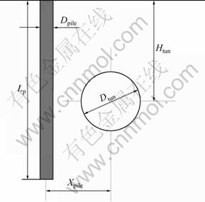
Fig.1 Relative location of tunnel and pile
The displacement controlled model (DCM) proposed by CHENG (2007) was used to simulate the volume loss effects. The applied displacements in the DCM were computed based on observations of convergence patterns around tunnels from centrifuge tests and field cases. PANG [15] carried out a comprehensive three-dimensional finite element analysis to investigate a case history from part of the MRT North East Line in Singapore. The study has shown that the pile response in the longitudinal direction is not as substantial as that in the transverse direction. The pile lateral deflection in the transverse direction was found to be 2-4 times higher than the response in the longitudinal direction. Besides, the bending moment in the transverse direction was equal or greater than that in the longitudinal direction up to 5 times. For simplicity, plane strain tunnel model was adopted in all the subsequent analyses. Figure 2 shows the tunnel transverse deformation.
3 Reference example
3.1 Presentation
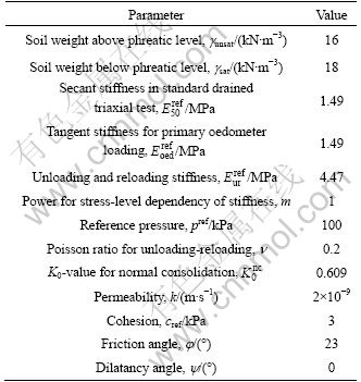
The reference example concerns the centrifuge tests carried out by ONG to verify the numerical model presented above. Unless otherwise stated, the test results are presented in prototype scale hereinafter. The tunnel diameter and cover depth are equal to Dtun=6 m and Htun=15 m, respectively. The behaviour of the tunnel lining is assumed to be governed by a linear-elastic relation with elastic modulus E=200 GPa and a Poisson ratio n=0.2. The pile length and width are equal to Lp= 22 m and Dpile=1.2 m. The axial stiffness and bending stiffness of the pile are equal to EA=36 400 MN and EI= 3 970 MN?m2, respectively. The distance between the pile axis and the tunnel centre is equal to Xpile=6 m. The soil behaviour is supposed to be governed by H-S constitutive model. Table 1 summarizes the characteristics of the soil.

Fig.2 Deformation of tunnel cross-section
Table 1 Parameters of soil
Due to symmetry, only one-half of the centrifuge setup was modelled. The finite element mesh shown in Fig.3 has an overall dimension similar to the centrifuge container size, i.e. length of 26 m, width of 20 m and height of 28 m. It is assumed that no horizontal or vertical displacement at the bottom boundary as it is beyond the influence of tunnel excavation. The mesh sides were restrained from moving laterally but free to settle. The right-hand boundary was the line of symmetry. The ground water level was at the ground surface. Pile and tunnel were simulated by solid element and tunnel model, respectively. The volume loss was 3.3% according to the centrifuge tests.
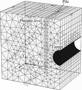
Fig.3 Three-dimensional finite element mesh
3.2 Numerical analysis results
Figure 4 shows the comparison of computed tunnelling-induced axial force, bending moment and lateral deflection with the experimental data. The pile lateral deflection is similar to the observations from the centrifuge test. Generally, the numerical results over-predict both the axial force and bending moments. However, the variation trends of induced pile axial force and bending moments along its length are similar to the test results. Multiple parametric study has been conducted and it is found that with the adjustment of soil parameters, it is not able to match all the axial forces, bending moments and lateral pile deflections, and the presented results are the best comprised results. It is suspected that the model pile surface is much smoother than that of actual pile since a smooth Perspex coating had been used on the model pile surface to protect the installed strain gauges. As such, the model pile responses due to soil lateral pressure become smaller than the actual piles with a generally much roughened pile surface. And the reported volume loss in this work may be larger than the actual volume loss in the test. However, it should be noted that the numerical predictions generally over-estimate the pile responses and are thus on the conservative side which is safe from a design point of view. Subsequently, a set of parametric studies is implemented using the finite element model mentioned above.
4 Parametric studies
A set of parametric studies was carried out by varying the normalised tunnel-pile distance (Xpile/Dtun), pile length to tunnel depth ratio (Lp/Htun) and tunnel volume loss (VL). The 3-D FE model as described in Sections 2 and 3 was adopted, i.e. plane strain tunnel and H-S model for soil. Unless otherwise specified, VL of 1% was assigned and the soil was modelled as soft clay. Besides, the pile was considered stress free prior to tunnelling (i.e. without working load at the pile head). Furthermore, it is difficult to assign an appropriate loading to the pile since the pile length is to be varied in the parametric studies. Figure 5 shows the geometry and pile position investigated. Xpile/Dtun of 1.0, 1.5 and 2.0 and Lp/Htun of 0.6, 0.8, 1.0 and 1.4 were investigated. These positions were arranged in a way to cover the zones of influence differentiated by lines projecting 45�� from the tunnel springline. Pile diameter and stiffness of 1.2 m and 23 GPa were assumed throughout the analyses unless specified, respectively.
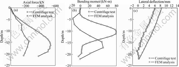
Fig.4 Comparison of results between finite element analysis and tests: (a) Pile axial force; (b) Pile bending moment; (c) Pile lateral deflection
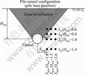
Fig.5 Pile base position investigated in parametric studies
4.1 Pile settlement
Figure 6 shows the settlement of piles at various Lp/Htun and constant Xpile/Dtun of 1.0. For comparison, the greenfield soil settlement (without pile) at the same location is also plotted in the same figure. It can be seen that the settlement of piles in the zone of influence i.e. Lp/Htun of 0.6 and 0.8 is higher than the greenfield surface settlement. The pile settlement reduces tremendously when the pile length is increased (i.e. Lp/Htun of 1.0 and 1.4). In this case, the pile head settlement becomes less than the greenfield surface settlement owing to the support from ��toe effect�� (i.e. pile length extending outside the zone of influence) and the high axial stiffness of pile. Looking closely into all the results, it can be concluded that the line that differentiates the two behaviours is projected at an angle of 45�� from the tunnel springline (Fig.5). The zone of influence is defined by the pile settlement greater or equal to soil surface settlement; whereas the pile settlement is less than the oil surface settlement outside the zone of influence. This is similar to the field observation by KAALBERG et al [16] and SELEMETAS et al [17].
The magnitude of pile head settlement is observed to vary significantly with Xpile/Dtun, Lp/Htun and VL, as shown in Fig.7. The figure represents the parameters which correspond to a pile settlement of 1% pile diameter. Within 1% pile diameter, which is widely used in the piling industry, the pile shaft friction is likely to be fully mobilised. The volume loss is found to be increasingly proportional to Xpile/Dtun and Lp/Htun. For Lp/Htun beyond 1.0, the pile settlement becomes less significant and requires higher volume loss to give the same settlement. The results for Lp/Htun of 2.0 and 3.0 are not plotted as they are generally out of the range of practical volume loss. For a typical 1.2 m diameter pile with Xpile/Dtun of 1 and tunnel volume loss controlled below 1.5%, the pile settlement is generally less than 1% of the pile diameter (i.e. 12 mm).
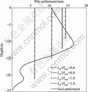
Fig.6 Pile settlement profile at various Lp/Htun ratio
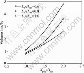
Fig.7 Variation of VL with Xpile/Dtun and Lp/Htun to obtain pile settlement of one percent pile diameter
4.2 Pile axial force
Figure 8 shows the distribution of axial force in piles at various Lp/Htun and constant Xpile/Dtun of 1.0. Generally, both compressive and tensile forces can be induced in a pile due to tunnelling, depending on the pile base location relative to the zone of influence. For a pile base located within the zone of influence (Fig.5), the pile is mainly subjected to tensile force (Fig.8). This is due to the relative movement between the pile and the soil around it. However, when the pile base is located outside the zone of influence, negative skin friction is developed along the upper pile shaft and leads to dragload (i.e. compressive force) in the pile. This can be observed by an increasing compressive force along the upper pile shaft. In order to support the dragload, positive skin friction is developed in the lower pile shaft. Furthermore, the base resistance will be mobilised if the positive skin friction is fully mobilised.

Fig.8 Pile axial force distribution at various Lp/Htun ratios (VL=1%, Dpile=1.2 m, Xpile/Dtun=1.0)
Figure 9 shows the variation of maximum axial force with Lp/Htun, Xpile/Dtun and VL. Generally, the axial force increases proportionally to the increase of Lp/Htun and VL. Despite that, the axial force increases as Xpile/Dtun reduces. This is obvious as the soil movement is larger at the position nearer to the tunnel distance.
4.3 Pile lateral deflection
Figure 10(a) shows the pile lateral deflection at various Lp/Htun and Xpile/Dtun of 1.0. As can be observed that, the whole pile, with pile base in the zone of influence (Lp/Htun<1.0), moves in the same direction (i.e. toward the tunnel). However, the pile head moves laterally more than the pile tip, with pile base outside the zone of influence, because the upper portion of the model tunnel has a larger magnitude of over-cut than that of the lower portion. In this case, the pile deflection increases as the Lp/Htun increases.
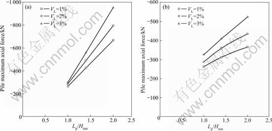
Fig.9 Variations of maximum axial force in pile with Lp/Htun and VL: (a) Dpile=1.2 m, Xpile/Dtun=1.0; (b) Dpile=1.2 m, Xpile/Dtun=2.0
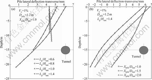
Fig.10 Pile lateral deflections at various Lp/Htun (a) and Xpile/Dtun (b)
Figure 10(b) shows the pile lateral deflection at various tunnel-pile distances (Xpile). Generally, the shape of pile lateral deflection is highly dependent on the distance between the tunnel and the pile. At various distances to tunnel, the maximum deflection point occurs at the pile head. The lateral deflection progressively becomes smaller as the distance increases.
4.4 Pile bending moment
Figure 11 shows the bending moments of piles at various Lp/Htun and constant Xpile/Dtun of 1.0. In term of magnitude, the tunnelling-induced bending moment increases with Lp/Htun. For the pile base located outside the zone of influence, the bending moment is greater compared with the pile base located within the zone of influence. This is caused by the restraining effect of pile length extended outside the zone of influence. The pile is restrained from large soil movement and in turn, induces a large bending moment.
Further analyses show that the bending moment can reach a constant value and be independent of Lp/Htun when Xpile/Dtun is greater than 1.0 or volume loss is small (i.e. VL=1%). However, this is only applicable to Lp/Htun ratio greater than 1.0. These can be observed in Fig.12 which shows the results of maximum bending moment plotted against Lp/Htun. Generally, very little change in maximum bending moment can be noted for Lp/Htun between 1.0 and 2.0.
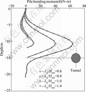
Fig.11 Pile bending moment at various Lp/Htun (VL=1.0%, Dpile= 1.2 m, Xpile/Dtun=1)
4.5 Effect of pile group
Assuming pile diameter of 1.2 m, length of 21 m and tunnel volume loss of 1%, analyses were carried out on pile group to study the group effect. Figure 13 shows the group composed of 2��2 piles with a spacing S= 0.5Dtun. The front piles (i.e. number I and II piles in Fig.13(b)) and rear piles (i.e. number III and IV piles in Fig.13(b)) were located at a distance Xpile=1.0Dtun and Xpile=1.5Dtun from the tunnel centre, respectively.
Figures 14(a) and (b) show a comparison of the response of the pile group to that of single piles located at equal horizontal distance from the tunnel centre. It is observed that the internal forces generated in the pile group are lower than those induced in single piles. This result shows a positive group effect, which is particularly important for rear piles, and reductions of about 65% of the maximum axial force and about 50% of the maximum bending moment are observed. The group effect is less important for the front piles, and a reduction of about 15% of the maximum axial force and an insignificant reduction of the bending moment are observed.
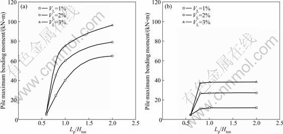
Fig.12 Variations of maximum bending moment in pile with Lp/Htun and VL: (a) Dpile=1.2 m, Xpile/Dtun=1.0; (b) Dpile=1.2 m, Xpile/Dtun= 2.0
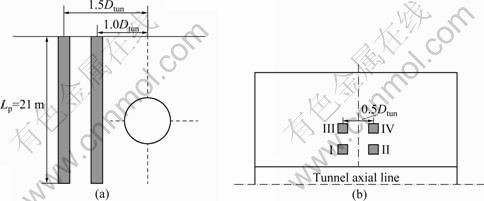
Fig.13 Layout of pile group: (a) Cross-section; (b) Top view
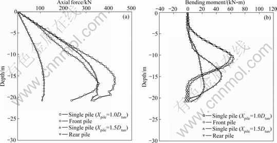
Fig.14 Tunnel construction adjacent to ��free-head�� group of piles: (a) Axial force; (b) Bending moment
5 Conclusions
1) A three-dimensional finite element technique using the displacement controlled model (DCM) to simulate the volume loss effect is presented, which provides an efficient analysis of tunnelling-induced pile responses through the back analysis of a centrifuge test.
2) There is a line that separates the two different zones which is projected at an angle of 45o from the tunnel springline. The zone of influence is defined by the pile settlement greater or equal to the soil surface settlement; whereas the pile settlement is less than the soil surface settlement outside the zone of influence.
3) Both the compressive and tensile forces can be induced in a stress-free pile (i.e. without working load at pile head) due to tunnelling, depending on the pile base location. For a pile base located within the zone of influence, the pile is mainly subjected to tensile force. When the pile base is located outside the zone of influence, negative skin friction is developed along the upper pile shaft and leads to dragload (i.e. compressive force) in the pile. Generally, the axial force increases proportionally to the increase of Lp/Htun and VL. Despite that, the axial force increases as Xpile/Dtun reduces.
4) The whole pile, with pile base in the zone of influence (Lp/Htun<1.0), moves in the same direction. However, the pile head moves laterally more than the pile tip, with the pile base outside the zone of influence. Besides, analyses show that the bending moment can reach a constant value and be independent of Lp/Htun when the Xpile/Dtun is greater than 1.0 or volume loss is small (i.e. 1% or less). However, this is only applicable when the Lp/Htun ratio is greater than 1.0.
5) The responses of pile are found to be smaller in pile group compared with single pile, which indicates a positive group effect, particularly in rear piles.
References
[1] MORTON J D, KING K H. Effects of tunneling on the bearing capacity and settlement of piled foundations [C]// Proc Tunneling 79. London: IMM, 1979: 57-68.
[2] HEGARDEN H J A M, VAN DER POEL T J, VAN DER SCHRIER J S. Ground movements due to tunneling: Influence on pile foundations [C]// Proc Int Symposium on Geotechnical Aspects of Underground Construction in Soft Ground. Rotterdam: Balkema, 1996: 519-524.
[3] LOGANATHAN N, POULOS, H G, STEWART D P. Centrifuge model testing of tunneling induced ground and pile deformations [J]. Geotechnique, 2000, 50(3): 283-294.
[4] JACOBSZ S W, STANDING J R, MAIR R J, SOGA K, HAGIWARA T, SUGIYAMA T. The effects of tunneling near single driven piles in dry sand [C]// Proc of Asian Regional Conf on Geotechnical Aspects of Underground Construction in Soft Ground. Shanghai: Tongji University, 2001: 29-35.
[5] ONG C W, LEUNG C F, CHOW Y K. Experimental study of tunnel-soil-pile interaction [C]// Proc Underground Singapore. Singapore: National University of Singapore, 2007: 256-263.
[6] BROMS B B, PANDEY P C. Influence of ground movements from tunnelling on adjacent piles and remedial measures [C]// 5th International Geotechnical Seminar, Case Histories in Soft Clays. Singapore, 1987: 73-84.
[7] CHEN L T, POULOS H G, LOGANATHAN N. Pile responses caused by tunneling [J]. Journal of Geotechnical and Geoenvironmental Engineering, 1999, 125(3): 207-215.
[8] KITIYODOM P, MATSUMOTO T, KAWAGUCHI K. A simplified analysis method for piled raft foundations subjected to ground movements induced by tunneling [J]. Int J Numer Anal Meth Geomech, 2005, 29(15): 1485-1507.
[9] SURJADINATA J, HULL T S, CARTER J P, POULOS H G. Combined finite- and boundary-element analysis of the effects of tunneling on single piles [J]. International Journal of Geomechanics, 2006, 6(5): 374-377.
[10] LEE R G, TURNER A J, WHITWORTH L J. Deformations cased by tunneling beneath a piled structure [C]// Proc XIII Int Conf Soil Mechanics and Foundation Engineering. London: University Press, 1994: 873-878.
[11] MROUEH H, SHAHROUR I. Three-dimensional finite element analysis of the interaction between tunneling and pile foundations [J]. Int Journal for Numerical and Analytical Methods in Geomechanics, 2002, 26(3): 217-230.
[12] LEE T G K, NG C W W. Effects of advancing open face tunneling on an existing loaded pile [J]. Journal of Geotechnical and Geoenvironmental Engineering, ASCE, 2005, 131(2): 193-201.
[13] ONG C W, LEUNG C F, YONG K Y, CHOW Y K. Performance of pile due to tunneling-induced soil movements [C]// Proc of the World Tunnel Congress 2007 and 33rd ITA/AITES Annual General Assembly. London: Taylor & Francis, 2007: 256-263.
[14] CHENG C Y, DASARI G R, CHOW Y K, LEUNG C F. Finite element analysis of tunnel-soil-pile interaction using displacement controlled model [J]. Tunnelling and Underground Space Technology, 2007, 22(4): 450-466.
[15] PANG C H. The effects of tunnel construction on nearby piled foundation [D]. Singapore: National University of Singapore, 2006.
[16] KAALBERG F J, TEUNISSEN E A H, VAN TOL A F, BOSCH J W. Dutch research on the impact of shield tunnelling on pile foundations [C]// 5th International Symposium on Geotechnical Aspects of Underground Construction in Soft Ground. London: Taylor & Francis, 2006: 1615-1620.
[17] SELEMETAS D, STANDING J R, MAIR R J. The response of full-scale piles to tunneling [C]// 5th International Symposium on Geotechnical Aspects of Underground Construction in Soft Ground. London: Taylor & Francis, 2006: 763-769.
(Edited by PENG Chao-qun)
Received date: 2010-05-14; Accepted date: 2010-10-22
Corresponding author: SUN Qing, PhD candidate; Tel: +86-21-65983386; E-mail: sunqingking12345@163.com
