
J. Cent. South Univ. (2012) 19: 1138-1147
DOI: 10.1007/s11771-012-1120-4![]()
FEM analyses for influences of stress-chemical solution on
THM coupling in dual-porosity rock mass
ZHANG Yu-jun(�����)1, YANG Chao-shuai(�˧)2
1. State Key Laboratory of Geomechanics and Geotechnical Engineering, Institute of Rock and Soil Mechanics,The Chinese Academy of Sciences, Wuhan 430071, China;
2. Technical Centre, China Railway Tunnel Group Co. Ltd, Luoyang 471009, China
? Central South University Press and Springer-Verlag Berlin Heidelberg 2012
Abstract:
The models of stress corrosion, pressure solution and free-face dissolution/precipitation were introduced. Taking a hypothetical nuclear waste repository in an unsaturated dual-porosity rock mass as the calculation objective, four cases were designed: 1) the fracture aperture is a function of stress corrosion, pressure solution and free-face dissolution/precipitation; 2) the fracture aperture changes with stress corrosion and pressure solution; 3) the fracture aperture changes with pressure solution and free-face dissolution/precipitation; 4) the fracture aperture is only a function of pressure solution, and the matrix porosity is also a function of stress in these four cases. Then, the corresponding two-dimensional FEM analyses for the coupled thermo-hydro-mechanical processes were carried out. The results show that the effects of stress corrosion are more prominent than those of pressure solution and free-face dissolution/precipitation, and the fracture aperture and relevant permeability caused by the stress corrosion are only about 1/5 and 1/1000 of the corresponding values created by the pressure solution and free-face dissolution/precipitation, respectively. Under the action of temperature field from released heat, the negative pore and fracture pressures in the computation domain rise continuously, and are inversely proportional to the sealing of fracture aperture. The vector fields of flow velocity of fracture water in the cases with and without considering stress corrosion are obviously different. The differences between the magnitudes and distributions of stresses within the rock mass are very small in all cases.
Key words:
1 Introduction
Due to the serious requirement of energy, resource and environment, the rock layer below 1 000-3 000 m from the surface may become the site of geothermal development, drawing petroleum, mineral stopping, embedding high level radioactive waste and CO2 [1]. In this part, all of the stress, temperature, pressure of the water and the gas are quite high. The thermal-hydro- mechanical-chemical coupling (THMC) caused by the engineering will happen in the process, and then the physical and mechanical nature of rock mass will be strongly influenced. So, it is of significant importance for an understanding of the flow and transport characteristics of the fractured rocks and the effective recovery of energy resources to investigate the evolution of fracture aperture, pore size and permeability under the condition of high pressure and temperature in the deep geological environment [2-3].
In the deep rock layer with a combined condition, the opening and the closing of fracture are mainly influenced by three aspects from mechanical and chemical actions. The first one is stress corrosion [4]; the second one is pressure solution [5]; the third one is free-face dissolution/precipitation [6]. A great number of studies have been carried out. DOVE [7] developed an empirical expression of Mode I crack velocity due to chemical dissolution by laboratory test. Based on the experimental data, YASUHARA and ELSWORTH [8] established models which separately account for stress corrosion and pressure solution, describing evolution of fracture aperture within a sample of novaculite containing a nature fracture. Sealing was reported in some tests at elevated temperature (>300 ��C) in sandstone made by TENTHOREY et al [9] and at modest temperature (50-150 ��C) in tuff carried out by LIN et al [10], and under low effective stress (0.2 MPa) with an acidic solution done by DURHAM et al [11]. Conversely, gaping was suggested in carbonate reservoirs by LIU et al [12] and DIJK and BERKOWITZ [13], and in the development of karst by PALMER [14] and POLYAK et al [15]. The lumped parameter model presented by YASUHARA et al [16], which considered the corrosion of mechanics and chemistry and effects of dissolution/ precipitation, was able to describe a spontaneous switch from fracture aperture opening to aperture sealing (or from permeability reduction to increment). This is an academic achievement with much practical value, but it is not used in numerical analysis of finite element method (FEM) so far.
Therefore, the models of stress corrosion, pressure solution and free-face dissolution/precipitation by YASUHARA et al [16] were introduced to the FEM code for verifying the effectiveness of them. Taking a hypothetical nuclear waste repository in an unsaturated dual-porosity rock mass as calculation objective, the FEM analysis coupled thermo-hydro-mechanical (THM) process was carried out. During the iteration of time increment, the fracture aperture was modified timely and the change of fracture permeability coefficient with stress corrosion, pressure solution and free-face dissolution/precipitation was established according to the ��cubic law�� of permeability and aperture. Meanwhile, the dynamic change of porosity and pore permeability with stress was given by DAVIS et al [17]. There are four cases computed in all: 1) the fracture aperture is a function of stress corrosion, pressure solution and free-face dissolution/precipitation (SC+PS+FD); 2) the fracture aperture changes with stress corrosion and pressure solution (SC+PS); 3) the fracture aperture changes with pressure solution and free-face dissolution/ precipitation (PS+FD); 4) the fracture aperture is only a function of pressure solution (PS). And the matrix porosity is also a function of stress in these four cases. The states of temperatures, rate and magnitude of fracture aperture, water pressures in porous and fracture, flow velocities and stresses in the near field of disposal repository were studied.
2 Aperture and permeability of fracture
2.1 Coupled model and FEM code
For the dual-porosity medium, it can be considered that there exist pore pressure and fracture pressure, but the fields of stress and temperature are single, respectively. So one kind of model for coupled thermo-hydro-mechanical process is created and the relative two-dimensional code of finite element method is developed. The detail was presented in Ref. [18] and the rationality of this model was verified in Ref. [19].
2.2 Fracture aperture
It can be seen in Fig. 1 that there exists a set of fractures in three-dimensional rock matrix, of which the aperture and spacing are b and s, respectively, and the
angle cosines between normal N of crack face and coordinate axis are
cos(N, x)=��, cos(N, y)=��, cos(N, z)=�� (1)

Fig. 1 Three-dimensional fractured rock
There are n (1/s) fractures altogether within unit length (1 m) in direction vertical to the crack face, and then the total aperture is E=nb.
So, the hydraulic total aperture e of fracture is [20]
![]() (2)
(2)
where JRC is the roughness coefficient of fractures.
The mechanical aperture of fracture will be modified in term of pressure dissolution and free-face solution/precipitation in this work.
2.3 Fracture permeability
The fracture permeability can be obtained from Eq. (2):
![]() (3)
(3)
where g is gravitational acceleration (9.81 m/s2), and ![]() is kinematics viscosity (the magnitude relative to purified water at 20 ��C is 1.0��10-6 m2/s).
is kinematics viscosity (the magnitude relative to purified water at 20 ��C is 1.0��10-6 m2/s).
When there are K sets of fractures in rock mass, the expressions can be given in xy plane:
 (4)
(4)
In Ref. [21], there is
 (5)
(5)
where Ex and Ey are mechanical total apertures of x and y direction, respectively; Kt is the total permeability tensor; ��xi and ��yi are angle cosines between normal direction of the i-th group of crack face and coordinate axis x and y, respectively.
2.4 Pore permeability
According to the empirical equation developed by DAVIS et al [17], when the stress in rock mass changes, the porosity and the pore permeability of the rock matrix can be improved as
![]() (6)
(6)
![]() (7)
(7)
where f0 and k0 are the porosity and permeability of rock matrix at the stress state of zero, respectively; fr is residual porosity of rock matrix at a high stress state; ![]() is the mean effective stress; �� and c are the experimentally-determined parameters, respectively; Ff,k is the modification factor of pore permeability.
is the mean effective stress; �� and c are the experimentally-determined parameters, respectively; Ff,k is the modification factor of pore permeability.
3 Three mechanical-chemical factors of changing fracture aperture
3.1 Stress corrosion
Assuming that the asperity contacts of brittle materials, as schematically shown in Fig. 2, within a fracture are in Hertzian contacts, a circumferential crack at or outside the contact may be generated induced by the tensile stress ��t. And this crack is described as stress corrosion. Mode I crack rate for quartz is defined by DOVE [3], given as
![]()
![]() (8)
(8)
where vSi��O is Mode I crack rate caused by chemical dissolution; ![]() and
and ![]() are the experimentally- determined factors related to temperature, respectively;
are the experimentally- determined factors related to temperature, respectively; ![]() and
and ![]() are activation enthalpies; R is gas constant; T is temperature;
are activation enthalpies; R is gas constant; T is temperature; ![]() and
and ![]() are the experimentally-determined constants derived from the geometry of crack tip, respectively; KI is the stress intensity factor;
are the experimentally-determined constants derived from the geometry of crack tip, respectively; KI is the stress intensity factor; ![]() and
and ![]() always satisfying
always satisfying ![]() +
+![]() are the fractions of Si��O reacting with molecular water or hydroxyl ions, and there will be
are the fractions of Si��O reacting with molecular water or hydroxyl ions, and there will be ![]()
![]() at the low pH and
at the low pH and ![]()
![]() at the high pH.
at the high pH.
Given by YASUHARA and ELSWORTH [8], the closing rate of fracture mechanical aperture due to stress corrosion is
![]() (9)
(9)
and
![]() (10)
(10)
![]() (11)
(11)
![]() (12)
(12)
![]() (13)
(13)
![]() (14)
(14)
where r is the distance parallel to the long axis direction of Mode I crack caused by ��t, and it is assumed to be infinitesimal as well as initial length of crack; �� is the Poisson ratio of material; ��t is the tensile stress induced by ��a, which reaches the maximum value just at the edge of the contact; ��a and ![]() are the real and nominal stress exerted over the contact area, respectively;
are the real and nominal stress exerted over the contact area, respectively; ![]() and
and ![]() are the real and nominal contact-area of the fracture asperity, respectively; dc is the real diameter of the asperity contact area, as shown in Fig. 3; Rc is the average contact-area ratio of the fracture, and Rc��1.
are the real and nominal contact-area of the fracture asperity, respectively; dc is the real diameter of the asperity contact area, as shown in Fig. 3; Rc is the average contact-area ratio of the fracture, and Rc��1.

Fig. 2 Schematic diagrams of fracture compaction induced by microcrack propagation [8]
Rc can be obtained from the following equation:
![]() (15)
(15)
where Es, Er and E0 are the mean, residual and initial apertures, respectively; Rc0 is the relative contact-area ratio at the reference stress; a is a empirical constant.
Therefore, the evolution of fracture mechanical aperture derived from stress corrosion is
![]() (16)
(16)
3.2 Pressure dissolution
As shown in Fig. 4, the dissolution rate, defined by YASUHARA et al [16], is expressed as
![]() (17)
(17)
where dMdiss/dt is the rate of addition of dissolved mass into solution at the interface; Vm is the molar volume of the solid; ��c is the critical stress that defines stress state where the compaction will effectively halt and reach equilibrium while ��a is equal to ��c; k+ is the dissolution rate constant of the solid; ��g is the density.
And
![]() (18)
(18)
![]() (19)
(19)
where ![]() is a constant factor; Ea is the activation energy; Em and Tm are the heat and the temperature of fusion, respectively.
is a constant factor; Ea is the activation energy; Em and Tm are the heat and the temperature of fusion, respectively.
The closing rate of fracture mechanical aperture caused by pressure solution is
![]()
![]() (20)
(20)
where Ep is the change of fracture mechanical aperture caused by pressure solution.
And the evolution of fracture aperture due to pressure solution can be expressed as
![]() (21)
(21)
3.3 Free-face dissolution/precipitation
It can be defined by the dissolution/precipitation rate constant and difference between the mineral concentration in the pore space and the equilibrium concentration:
![]() (22)
(22)
![]() (23)
(23)
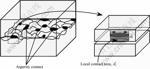
Fig. 3 Idealized representation of asperity contact condition [5]
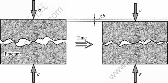
Fig. 4 Schematic diagram of pressure solution for fractured rock comprising a discontinuity [5]
and
![]() (24)
(24)
![]() (25)
(25)
![]() (26)
(26)
where ![]() and
and ![]() are the dissolution and the precipitation mass fluxes at the free-face, respectively; Apore is the area of the fracture void with a value of
are the dissolution and the precipitation mass fluxes at the free-face, respectively; Apore is the area of the fracture void with a value of ![]() m denotes the reaction order, which is experimentally constrained; cpore is the mineral concentration in the pore space; ceq is the equilibrium solubility of the dissolved mineral; dMdiff/dt is the diffusive mass flux; �� is the thickness of the water film trapped at the interface; Db is the diffusion coefficient; a is an infinitesimal length (which set by Yasuhara to be 1/1 000 of the diameter of the initial asperity contact) substituted to avoid a singularity in integrating Fick��s first law to the center of a circular contact area; cint,x=a and
m denotes the reaction order, which is experimentally constrained; cpore is the mineral concentration in the pore space; ceq is the equilibrium solubility of the dissolved mineral; dMdiff/dt is the diffusive mass flux; �� is the thickness of the water film trapped at the interface; Db is the diffusion coefficient; a is an infinitesimal length (which set by Yasuhara to be 1/1 000 of the diameter of the initial asperity contact) substituted to avoid a singularity in integrating Fick��s first law to the center of a circular contact area; cint,x=a and ![]() are mineral concentrations in the interface fluid and pore space, respectively. k- is the precipitation rate constant of the mineral;
are mineral concentrations in the interface fluid and pore space, respectively. k- is the precipitation rate constant of the mineral; ![]() is the constant factor; Eb is activation enthalpy.
is the constant factor; Eb is activation enthalpy.
The evolution of fracture mechanical aperture due to free-face dissolution/precipitation can be expressed as
![]() (27)
(27)
Therefore, the total mechanical aperture impacted by the three kinds of factors mentioned above can be given at the time of t+��t:
![]() (28)
(28)
Finally, the models of the stress corrosion, pressure dissolution and free-face dissolution/precipitation are to be introduced into the FEM code of coupled THM for the dual-porosity rock mass.
4 Computation example
As shown in Fig. 5, it is assumed that a canister filled with the vitrified radioactive nuclear waste is disposed at the depth of 1 000 m beneath the ground surface, and the quartzite is packed around the canister that is an unsaturated dual-porosity medium. As an approximate simplification, it is treated to be a plane strain problem. A computation region with a horizontal length of 4 m and a vertical length of 8 m is taken. There are 800 elements and 861 nodes in the mesh. From the margin of the vitrified waste to right side, the node numbers are 432, 433, 434, 435 and 436, respectively.
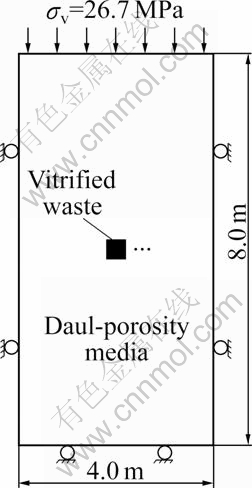
Fig. 5 Computation model (Pw1=-4.59 MPa, Pw2=-0.46 MPa, T=20 ��C)
The boundary conditions are as follows: the free displacement is allowed for the top of computation domain over which the vertical distributed load of ��v=26.7 MPa is exerted. The displacements of both the left and right sides are fixed horizontal displacements. The displacement of the bottom face is fixed vertical displacement. The pore pressure of -4.59 MPa, fracture pressure of -0.46 MPa and temperature of 20 ��C are fixed on all the boundary faces. There exist one set of horizontal fractures and one group of vertical fractures in rock matrix, respectively. And the state of coupled THM is to play a role of stress corrosion, pressure solution and free-face dissolution/precipitation on the fracture aperture. The relative calculating parameters are tabulated in Table 1, Table 2 and Table 3 (the primary data are originated from Refs. [5, 16]). At the initial state, the values of pore pressure, fracture pressure and temperature in the rock mass are the same as those at the boundary, respectively. The waste radiates continuously heat with a constant power of 1 000 W during a period of 6 a.
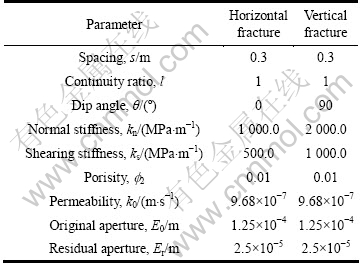
Table 1 Main computation parameters
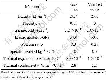
Table 2 Parameters for fracture sets used in calculation
The water retention curves of both porous and fracture medium conform to the van Genuchten model, that is
![]() (29)
(29)
where ��=3.86��10-6 m-1 and ��=1.41 for the rock matrix; and ��=5.26��10-4 m-1 and ��=2.55 for the fracture system; ��=1-1/��; �� is the water potential head; sws is the maximum saturation with a magnitude of 1.0; swr is the minimum saturation, the magnitudes of which are 0.19 for the rock mass and 0.01 for the fracture rock, respectively.
The relationship between relative permeability and saturation degree is
![]() (30)
(30)
Both the thermal water diffusivities of the rock matrix and fracture system are taken as Dt=2.5��10-10 m2/(s����C).
The value of m in Eqs. (22) and (23) is approximately taken as 1 during computing.
For the four mentioned cases with different evolutions of fracture apertures, the distributions and changes of temperatures, apertures and permeabilities of fracture, pore pressures, flow velocities and principal stresses in rock mass are studied. The main computation results and analyses are as follows.
The differences of temperature change in calculation region for the four cases are insignificant. In the early 0.1 a, the temperature of the buffer increases fast, and then it increases slowly. At the termination of computation, the temperatures of nodes 432, 433, 434 and 435 for Case 1 are 77.8, 61.9, 52.6 and 45.7 ��C, respectively.
The horizontal fracture apertures versus horizontal distance from the center of the vitrified waste to the left at the time of 6 a are shown in Fig. 6. It can be seen that the closings of apertures occur apparently for both Cases 1 and 2, which decreases initial value from 1.25��10-4 m to (0.261 1-0.305 5)��10-4 m, and the magnitude for Case 2 is slightly smaller than that for Case 1. However, the corresponding magnitudes, which are a little larger for Case 3 and appreciably smaller for Case 4 than the initial values, respectively, are (1.250 1-1.253 3)��10-4 m and (1.246 9-1.249 9)��10-4 m, respectively. So, it is inferred that in this specific condition, the impact of stress corrosion contributing to the closing of horizontal fracture aperture is much more intensive than that of pressure solution, and the effect of free-face dissolution/ precipitation on horizontal fracture expansion is also slight. The qualitative and quantitative evolutions of the vertical fracture aperture are similar to the situations mentioned above. In the following, only Case 1 and Case 3 are taken as instances for analyses.
Table 3 Parameters for stress corrosion, pressure solution and free-face dissolution/precipitation

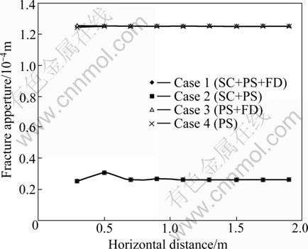
Fig. 6 Horizontal fracture apertures versus horizontal distance from centre of vitrified waste at 6 a
Contours of fracture aperture and matrix porosity within the range of 2 m �� 2 m around the canister at 6 a for Case 1 are shown in Fig. 7 (contours for Case 3 are similar with Case 1, not given here). At this moment, the values of node 433 are 0.305 5��10-4 m (for horizontal fracture), 0.250 0��10-4 m (for vertical fracture) and 0.098 (for porosity) for Case 1; 1.251 4��10-4 m (for horizontal fracture), 1.252 8��10-4 m (for vertical fracture) and 0.098 (for matrix porosity) for Case 3, respectively. In the calculation domain, most of the horizontal fracture apertures are smaller than those of vertical fracture, because the vertical stress is higher than the horizontal one in rock mass. The changes of porosity for the two cases are basically consistent, presenting decreasing trend for both cases. This reflects the compressive effect of stress and shows that the change of porosity is independent on the fluctuating of fracture aperture. The permeability coefficients of node 433 are 8.45��10-10 m/s (for horizontal fracture), 3.10��10-10 m/s (for vertical fracture) and 9.883��10-14 m/s (for matrix porosity) for Case 1; 9.74��10-7 m/s (for horizontal fracture), 9.79��10-7 m/s (for vertical fracture) and 9.883��10-14 m/s (for matrix porosity) for Case 3, respectively. The values of fracture permeability for Case 1 are quite smaller than those for Case 3.
Pore and fracture water pressures versus time at nodes 432, 433, 434, 435 for Case 1 are shown in Fig. 8, respectively. It can be seen that closing of fracture aperture is quite large due to the effect of stress corrosion, pressure solution and free-face dissolution/precipitation for Case 1 while the fracture aperture expands slightly because the factors only contain pressure solution and free-face dissolution/precipitation for Case 3. In addition, under the action of temperature field from the releasing heat of nuclear waste, the negative pore and fracture pressures increase greatly for Case 1 while fracture pressure increases slightly in spite of a significant growth of negative pore pressure for Case 3. At the time of 6 a, the pressures of pore and fracture at node 433 are -9.31 MPa and -3.40 MPa for Case 1 and -7.58 MPa and -0.46 MPa for Case 3, respectively. Contours of pore and fracture pressures in rock mass at the time of 6 a for Case 1 and Case 3 are shown in Fig. 9 and Fig. 10, respectively. It can be seen that fracture pressure in the near field of canister, compared with that for Case 3, is rising significantly due to the effects of stress corrosion, pressure solution and free-face dissolution/precipitation for Case 1.
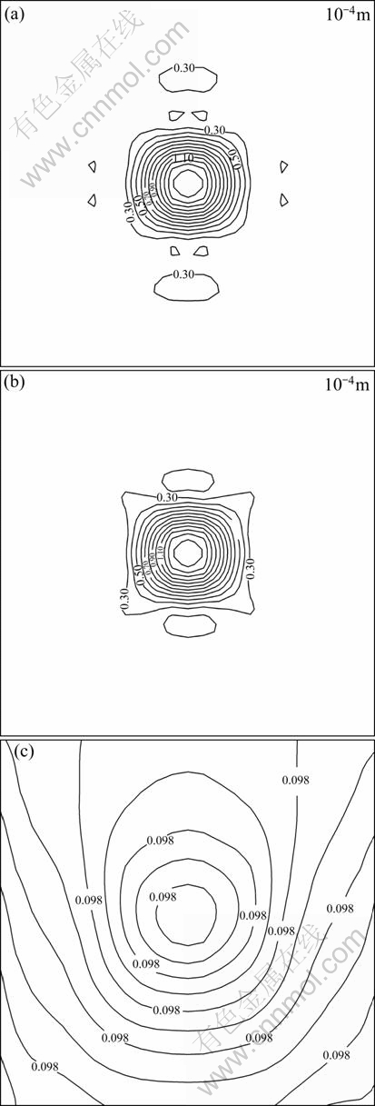
Fig. 7 Contours of fracture aperture and matrix porosity in rock mass at 6 a for Case 1: (a) Horizontal fracture aperture; (b) Vertical fracture aperture; (c) Matrix porosity
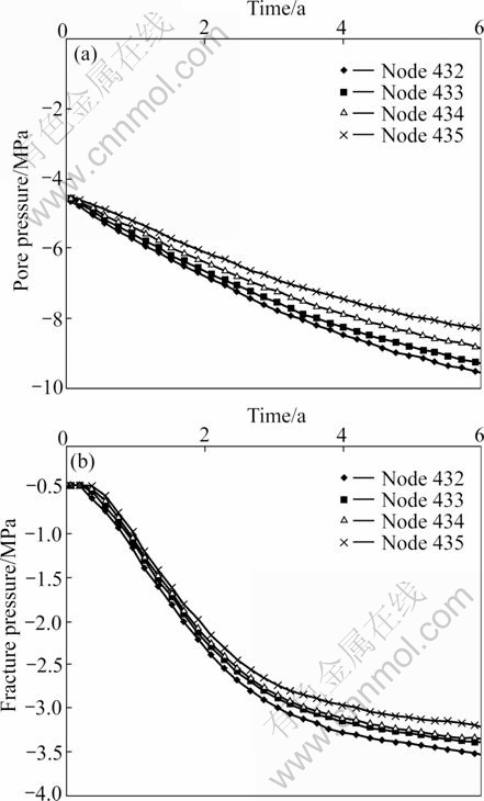
Fig. 8 Pore and fracture water pressures versus time at some nodes for Case 1: (a) Pore pressure; (b) Fracture pressure

Fig. 9 Contours of pore and fracture pressures in rock mass at 6 a for Case 1 (MPa): (a) Pore pressure; (b) Fracture pressure
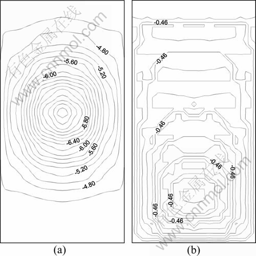
Fig. 10 Contours of pore and fracture pressures in rock mass at 6 a for Case 3 (MPa): (a) Pore pressure; (b) Fracture pressure
Flow vectors of pore and fracture water in calculation domain at 6 a for Case 1 and Case 3 are shown in Fig. 11 and Fig. 12, respectively. It is found that the flow vectors of pore and fracture water for Case 3, compared with those for Case 1 containing the effects of stress corrosion, pressure solution and free-face dissolution/precipitation, are quite different, especially in the vicinity of canister. Taking node 433 for instance, the flow velocities of pore and fracture water are 3.46�� 10-8 m/s and 1.79��10-8 m/s for Case 1, and 2.94��10-8 m/s and 14.03��10-8 m/s for Case 3, respectively.
Generally, the differences among stress magnitudes in calculation domain for the four cases are quite small because negative pore and fracture pressures are not thought to affect stress field [1]. Taking Case 1 for instance, normal stress contours in calculation domain at 6 a are drawn in Fig. 13. It can be seen that the stresses under the action of temperature field from the releasing heat of nuclear waste are different from those caused only by deadweight of overburden (stresses contours of the latter are horizontal lines). At the time of 6 a, the horizontal and vertical stresses at the midpoint in the right edge of canister are -0.102 MPa and -26.745 MPa, respectively.
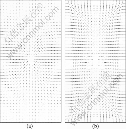
Fig. 11 Flow vectors of pore and fracture water in calculation domain at 6 a for Case 1: (a) Pore velocity; (b) Fracture velocity
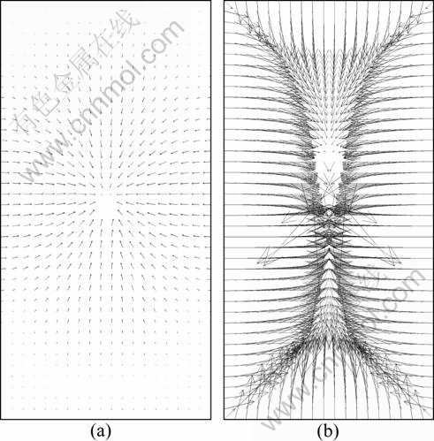
Fig. 12 Flow vectors of pore and fracture water in calculation domain at 6 a for Case 3: (a) Pore velocity; (b) Fracture velocity
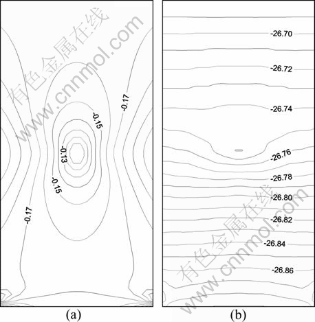
Fig. 13 Normal stress contours in calculation domain at 6 a for Case 1 (MPa): (a) Horizontal normal stress; (b) Vertical normal stress
5 Conclusions
1) The temperatures for these four cases are basically the same, and at the time of 6 a which is also the end of computation, they can reach 20.0-88.0 ��C from the boundary of near field to the centre of canister.
2) The effects of stress corrosion on aperture and permeability of fracture are more intensive than those of pressure solution and free-face dissolution/precipitation. The stress corrosion decreases aperture and permeability of fracture significantly while the pressure solution and free-face dissolution/precipitation only impel them to increase or decrease slightly. For comparison, the fracture aperture and relevant permeability caused by the stress corrosion are only about 1/5 and 1/1 000 of the corresponding values created by the pressure solution and free-face dissolution/precipitation, respectively.
3) Under the action of temperature field from the releasing heat of nuclear waste, the negative pore and fracture pressures in the computation domain rise continuously, but they change rapidly firstly and then slowly. The values of them are inversely proportional to the changes of fracture aperture and permeability. The vector fields of flow velocity of fracture water in the cases with and without stress corrosion are obviously different.
4) For the reason of releasing heat from nuclear waste, the stress fields in rock mass are different from those caused only by deadweight of overburden, and differences of magnitudes and distributions of stresses in all the cases are quite small.
References
[1] TARON J, ELSWORTH D. Thermal-hydrologic-mechanical- chemical processes in the evolution of engineered geothermal reservoirs [J]. International Journal of Rock Mechanics and Mining Sciences, 2009, 46(5): 855-864.
[2] AIFANTIS E. On the problem of diffusion in solids [J]. Acta Mech, 1980, 37: 265-296.
[3] TARON J, ELSWORTH D. Coupled mechanical and chemical processes in Engineered geothermal reservoirs with dynamic permeability [J]. International Journal of Rock Mechanics and Mining Sciences, 2010, 47(8): 1339-1348.
[4] NARA Y, KANEKO K. Study of subcritical crack growth in andesite using the double torsion test [J]. Int J Rock Mech Min Sci, 2005, 42(4): 521-530.
[5] YASUHARA H, ELSWORTH D. Evolution of permeability in a natural fracture: Significant role of pressure solution [J]. J Geophys Res, 2004, 109: B03204, doi:10.1029/2003JB002663.
[6] DREYBRODT W, BUHMANN D. A mass transfer model for dissolution and precipitation of calcite from solutions in turbulent motion [J]. Chem Geol, 1991, 90: 107-122.
[7] DOVE M. Geochemical controls on the kinetics of quartz fracture at subcritical tensile stresses [J]. J Geophys Res, 1995, 100(B11): 22349-22359.
[8] YASUHARA H, ELSWORTH D. Compaction of a rock fracture moderated by competing roles of stress corrosion and pressure solution [J]. Pure Appl Geophys, 2008, 165: 1289-1306.
[9] TENTHOREY E, COX S, TODD H. Evolution of strength recovery and permeability during fluid-rock reaction in experimental fault zones [J]. Earth and Plane Sci Lett, 2003, 206: 161-172.
[10] LIN W, ROBERTS J, GLASSLEY W, RUDDLE D. Fracture and matrix permeability at elevated temperatures [R]. Workshop on Significant Issures and Available Data, Near-field/Altered-zone Coupled Effects Expert Elicitation Project, San Francisco, 1997.
[11] DURHAM W, BOURCIER W, BURTON E. Direct observation of reactive flow in a single fracture [J]. Water Resour Res, 2001, 37: 1-12.
[12] LIU X, ORMOND A, BARTKO K, LI Y, ORTOLEVA P. A geochemical reaction-transport simulator for matrix acidizing analysis and design [J]. Pet Sci Eng, 1997, 17: 181-196.
[13] DIJK P, BERKOWITZ B. Buoyancy-driven dissolution enhancement in rock fractures [J]. Geology, 200, 28(11): 1051-1054.
[14] PALMER A. Origin and morphology of limestone caves [J]. Geol Soc Am Bull, 1991, 103: 1-21.
[15] POLYAK V, MCINTOSH W, G?VEN N, PROVENCIO P. Age and origin of Carlsbad cavern and related caves from 40Ar/39Ar of alunite [J]. Science, 1998, 279: 1919-1922.
[16] YASUHARA H, ELSWORTH D, POLAK A, LIU J, GRADER A, HALLECK P. Spontaneous switching between permeability enhancement and degradation in fractures in carbonate: Lumped parameter representation of mechanically-and chemically-mediated dissolution [J]. Transport in Porous Media, 2006, 65: 385-409.
[17] DAVIS J, DAVIS D. Stress-dependent permeability: Characterization and modeling [R]. Society of Petroleum Engineers, SPE Paper no. 56813, 1999.
[18] ZHANG Yu-jun. Coupled thermo-hydro-mechanical model and finite element analyses of dual-porosity fractured medium for ubiquitous-joint rock mass [J]. Chinese Journal of Rock Mechanics and Engineering, 2009, 28(5): 947-955. (in Chinese)
[19] ZHANG Yu-jun, ZHANG Wei-qing. Finite element analysis of influence of pressure solution of fracture aperture on T-H-M coupling in dual-porosity medium [J]. Rock and Soil Mechanics, 2010, 31(4): 1269-1275. (in Chinese)
[20] OLSSON R, BARTON N. An improved model for hydromechanical coupling during shearing of rock joints [J]. Int J Rock Mech Min Sci, 2001, 38(3): 317-329.
[21] ZHOU Wei-yuan. Advanced rock Mechanics [M]. Beijing: Hydranlic and Electric Power Press, 1990: 276-282.
(Edited by HE Yun-bin)
Foundation item: Project(2010CB732101) supported by the National Basic Research Program of China; Project(51079145) supported by the National Natural Science Foundation of China; Project(2009BAK53B03) supported by the National Key Technology R&D Program of China
Received date: 2011-02-22; Accepted date: 2011-05-19
Corresponding author: ZHANG Yu-jun, Professor, PhD; Tel: +86-27-87198482; E-mail: yjzhang@whrsm.ac.cn
Abstract: The models of stress corrosion, pressure solution and free-face dissolution/precipitation were introduced. Taking a hypothetical nuclear waste repository in an unsaturated dual-porosity rock mass as the calculation objective, four cases were designed: 1) the fracture aperture is a function of stress corrosion, pressure solution and free-face dissolution/precipitation; 2) the fracture aperture changes with stress corrosion and pressure solution; 3) the fracture aperture changes with pressure solution and free-face dissolution/precipitation; 4) the fracture aperture is only a function of pressure solution, and the matrix porosity is also a function of stress in these four cases. Then, the corresponding two-dimensional FEM analyses for the coupled thermo-hydro-mechanical processes were carried out. The results show that the effects of stress corrosion are more prominent than those of pressure solution and free-face dissolution/precipitation, and the fracture aperture and relevant permeability caused by the stress corrosion are only about 1/5 and 1/1000 of the corresponding values created by the pressure solution and free-face dissolution/precipitation, respectively. Under the action of temperature field from released heat, the negative pore and fracture pressures in the computation domain rise continuously, and are inversely proportional to the sealing of fracture aperture. The vector fields of flow velocity of fracture water in the cases with and without considering stress corrosion are obviously different. The differences between the magnitudes and distributions of stresses within the rock mass are very small in all cases.
