
J. Cent. South Univ. (2016) 23: 2382-2396
DOI: 10.1007/s11771-016-3297-4

Limit equilibrium stability analysis of slopes under external loads
DENG Dong-ping(�˶�ƽ), ZHAO Lian-heng(������), LI Liang(����)
School of Civil Engineering, Central South University, Changsha 410075, China
 Central South University Press and Springer-Verlag Berlin Heidelberg 2016
Abstract:
Two calculation modes for the effect of external load on slope stability, i.e., mode I in which the external load is thought to act on slope surface, and mode II in which the external load is thought to act on slip surface along the force action line, were considered. Meanwhile, four basic distribution patterns of external load were used, of which complex external loads could be composed. In analysis process, several limit equilibrium methods, such as Swedish method, simplified Bishop method, simplified Janbu method, Spencer method, Morgenstern-Price (M-P) method, Sarma method, and unbalanced thrust method, were also adopted to contrast their differences in slope stability under the external load. According to parametric analysis, some conclusions can be obtained as follows: (1) The external load, with the large magnitude, small inclination angle, and acting position close to the slope toe, has more positive effect on slope stability; (2) The results calculated using modes I and II of external load are similar, indicating that the calculation mode of external load has little influence on slope stability; (3) If different patterns of external loads are equivalent to each other, their slope stability under these external loads are the same, and if not, the external load leads to the better slope stability, as action position of the resultant force for external load is closer to the lower sliding point of slip surface.
Key words:
1 Introduction
In natural and artificial slopes, various kinds of external loads, including concentrated forces and distributed forces with different patterns, act on the slope surface, and they have the important effects on slope stability. For example, reactions of the anchor cable with frame beam [1-4] can stabilize slope, and water pressure on slope surface [5-6] can reduce slope stability as the unfavorable load, etc. Thus, analyzing slope stability under external loads has significance on practical applications and can also provide guidance for slope reinforcement [7]. However, this aspect has not been fully analyzed, and detailed parametric analyses with the related calculation methods have yet not been studied.
About determining slope stability under external loads, two main aspects should be considered as follows: 1) calculation methods of slope factor of safety (FOS), and 2) calculation modes of external load. For the first aspect, many limit equilibrium (LE) methods, such as Swedish method [8], simplified Bishop method [9], simplified Janbu method [10], Spencer method [11], Morgenstern-Price (M-P) method [12], Sarma method [13], and unbalanced thrust method [14], can be adopted to calculate the slope FOS. However, among these calculation methods, different assumptions of inter-slice forces are adopted, so the results of slope stability obtained using them are slightly different. Moreover, different types of slip surfaces, such as arc and arbitrary curve [15-18], can also influence the slope FOS solutions with some difference to each other, but most of researchers only utilized the circular slip surface to simplify analysis process in the previous studies. For the second aspect, two calculation modes need to be considered on analyzing the effects of external loads on slope stability, including that 1) the external load is thought to act on slope surface, namely mode I, and 2) the external load is thought to act on slip surface along the force action line, namely mode II. At present, many scholars still think the external load acting on slip surface along its force action line to evaluate the slope stability. Actually, the external load locates at slope surface, and it can affect the force distribution of entire slip surface, not only the local slip surface near to its force action line. Meanwhile, the contributions of external load on the inter-slice forces are also different in two calculation modes. Therefore, these two modes have their own calculation characteristics. According to above analysis, the following factors, i.e., the calculation method of slope FOS, type of slip surface, and calculation modes of external load, should be all studied in the stability of slope under external loads.
In this work, we listed four basic distribution patterns of external loads, and complex external loads could be obtained by combining these basic patterns. Then, two calculation modes of external load, two types of slip surfaces, and different LE methods, were adopted. In the process of parametric analysis, the slope FOS, and the normal and shear forces on slip surface obtained using different methods, were compared, and the effects of these abovementioned factors on slope stability were also comprehensively analyzed.
2 Limit equilibrium methods for slope stability under external loads
As shown in Fig. 1, in order to assess the effect of external load on slope stability, two calculation modes of external load can be adopted, i.e., mode I in which the external load is thought to act on slope surface, as Qi1, and mode II in which the external load is thought to act on slip surface along the force action line, as Qi2. According to different assumptions of the inter-slice forces and calculation modes of the external load, four kinds of the vertical slice i, shown in Figs. 1(b)-(e), were obtained. Here, Figs. 1(b)-(d) indicate that mode I is adopted, and Figs. 1(c)-(d) indicate that mode II is adopted. Meanwhile, for Figs. 1(d)-(e), the inter-slice thrust Pi-1 is assumed parallel to the tangent of slip surface in slice i.
In Fig. 1, the forces acting on the slice i include: Qi (i.e., Qi1 and Qi2) is the external load with the horizontal inclination angle ��, which ranges 0��-90��, and Qi1 has the same position as Qi2 when ��=90��; Wi is the gravity; Ni and Si are the normal and shear force on slip surface, respectively; Ei-1 and Ei are the inter-slice normal forces on left and right sides, respectively; Xi-1 and Xi are the inter-slice shear forces on left and right sides, respectively. For facilitating to analyze slope stability, other parameters in the slice i are defined as hi (i.e., hi1 and hi2) is the vertical height between the action point of external load Qi (i.e., Qi1 and Qi2) and the midpoint of slip surface, and in the case of the divided slices with small widths, the action point of external load Qi is usually assumed to be on the vertical midline of slice i, which implies that hi2=0; bi is the width; ��i-1 and ��i are the horizontal inclination angles of the tangent of the midpoint on slip surface of slices i-1 and i, respectively; zi-1 and zi are the vertical heights between the action point of inter-slice normal forces Ei-1 and Ei and the boundary point on slip surface of slice i, respectively; lsi-1 and lsi are the vertical heights of left and right sides of slice i, respectively; A and B are thelower and upper sliding points of the slip surface, respectively.
Establishing the xy-axes coordinate system with slope toe as the origin, the external load Qi acts at point s1 on slope surface, i.e., Qi1, with the coordinates of (xp, yp), and acts at point s2 on slip surface along the force action line, i.e., Qi2, with the coordinates of (xs, ys). For the coordinates (xs, ys), it can be solved easily by calculating the intersection point s2 when the circular or arbitrary curved slip surface is known.
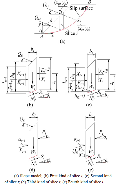
Fig. 1 Force analysis of vertical slice in slope under external load:
In Figs. 1(b)-(c), without considering the inter-slice forces on the slice i, the force equilibrium conditions along the normal direction of slip surface can be expressed as
 (1)
(1)
In Figs. 1(b)-(c), considering the inter-slice forces on the slice i, the force equilibrium conditions in the x- and y-axis directions can be expressed as
 (2a)
(2a)
 (2b)
(2b)
where  and
and 
Assuming arc as the slip surface, the moment equilibrium condition of all forces in the sliding body around arc center can be expressed as
 (3)
(3)
where 
In Figs. 1(b)-(c), considering the inter-slice forces on the slice i, the force equilibrium conditions along the tangential and normal directions of slip surface and the moment equilibrium condition around the midpoint of slip surface can be expressed as
 (4a)
(4a)
 (4b)
(4b)
 (4c)
(4c)
where  and
and 
In Figs. 1(d)-(e), considering the inter-slice forces on the slice i and adopting the inter-slice thrust instead of the inter-slice normal and shear forces, the force equilibrium conditions along the tangential and normal directions of slip surface can be expressed as
 (5a)
(5a)
 (5b)
(5b)
In Eqs. (1)-(5), and
and for the calculation mode I of external load, and
  and
and  for the calculation mode II of external load.
As the unstable sliding body typically satisfies Mohr�CCoulomb (M�CC) strength criterion, the relationship between the shear force Si and normal force Ni is given as
 (6)
(6)
where Fs is the slope FOS; c is the soil cohesion; �� is the soil internal friction angle; li is the length of slip surface in slice i.
By combining Eqs. (1), (3), and (6), the formulas for Fs of Swedish method can be obtained.
The shear force Si on slip surface was determined by combining Eqs. (2a) and (2b), and Si was substituted into Eq. (6) to solve the normal force Ni. Then, the formula for Fs of simplified Bishop method can be obtained by substituting Ni into Eq. (3) with allowing 
Given that  the formula for Fs of simplified Janbu method can be obtained by combining Eqs. (2) and (6) and allowing
In Spencer and Morgenstern-Price (M-P) methods, the relationship between the inter-slice normal force Ei and shear force Xi is assumed as
 (7)
(7)
where �� is the calculation parameter; fi is the inter- slice force correction function.
In Sarma method, the relationship of the inter-slice normal force Ei and shear force Xi is assumed to be subjected to M-C strength criterion, and it is expressed as
 (8)
(8)
where Fs is also the slope FOS; csi is the soil cohesion of the right side in the slice i; ��si is the soil internal friction angle of the right side in the slice i. Furthermore,  and
and 
Combining Eqs. (4a), (4b), and (4c), the recurrence formula of Ei in Spencer, M-P, and Sarma methods can be derived as
 (9)
(9)
Under the conditions E0=0 and En=0, the formula for Fs of Spencer, M-P, and Sarma methods can be obtained using Eq. (9). Under the conditions M0=0 and Mn=0, the calculation parameter �� in Spencer and M-P methods can be determined using Eq. (4c).
Combining Eqs. (5) and (6), the recurrence formula of Pi in unbalanced thrust method can be obtained as
 (10)
(10)
Under the conditions P0=0 and Pn=0, the formula for Fs of unbalanced thrust method can be obtained using Eq. (10).
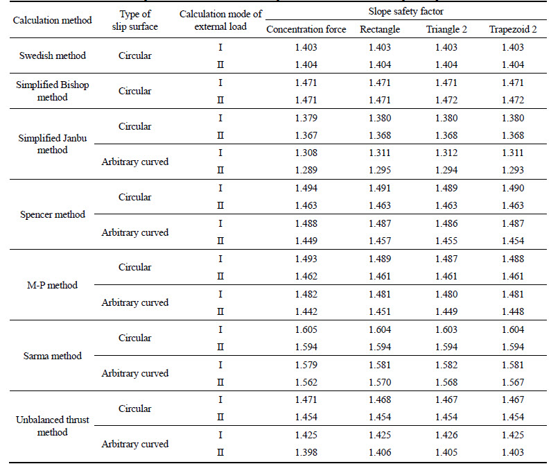
The formulas for parameters ��i, ��i-1, ��i-1, Ri, Ti, ��, and fi in Spencer, M-P, Sarma, and unbalanced thrust methods are listed in Table 1, and the formulas for Fs of Swedish method, simplified Bishop method, simplified Janbu method, Spencer method, M-P method, Sarma method, and unbalanced thrust method are listed in Table 2.
3 Distribution patterns of external load
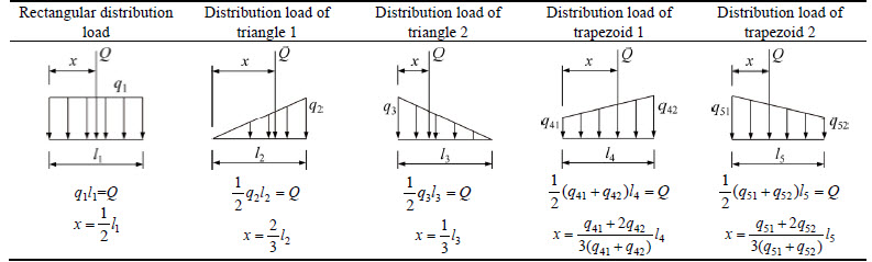
The external load acting on slope surface may be the concentration force, distribution load, or the combination of concentration force and distribution load. As shown in Table 3, in this work, the external load was divided into four basic distribution patterns as follows: 1) concentration force Q; 2) rectangular distribution load with length l1 and magnitude q1; 3) triangular distribution load (triangle 1 or triangle 2) with length l2 (or l3) and magnitude q2 (or q3), and 4) trapezoidal distribution load (trapezoid 1 or trapezoid 2) with length l4 (or l5) and magnitude q41 and q42 (q41<>42) (or q51 and q52 (q51>q52)). The relationships among the concentration force and distribution loads are also listed Table 3, for cases when the distribution load has the equivalent effect to the concentration force. Certainly, other complex external loads can be formed by combining these basic distribution patterns of external loads. Therefore, it is universal significance in studying the effects of these basic distribution patterns of external loads on slope stability.
Table 1 Calculation formula of parameters for different calculation methods
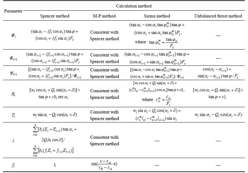
Table 2 Formula for calculating slope FOS in different calculation methods
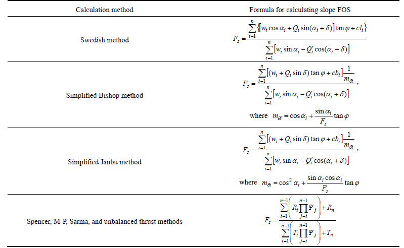
Table 3 Basic distribution patterns of external load
4 Comparison and analysis of examples
Example 1 [19]: as shown in Fig. 2, the slope height H=10 m with slope ratio=1:2, i.e., slope angle ��=26.565��, and the soil parameters are given as: natural unit weight ��=20.0 kN/m3, cohesion c=3.0 kPa, and internal friction angle ��=19.6��. The xy-axes coordinate system was established by setting slope toe as the origin. In Fig. 2, points A and B, respectively, are the lower and upper sliding points of slip surface, and their coordinates are (0 m, 0 m) and (10 m, 22 m), respectively. For the circular slip surface at the specific position, the arc radius R=30 m, and for the arbitrary curved slip surface, composed of fold lines with n segments and proposed by DENG et al [20], its parameters at the specific position are given as: ��1=-5��, x0=L/n, and n=100. Here, ��1 is the horizontal inclination angle of first segment fold line, x0 is the horizontal width of first segment fold line, L is the horizontal length of connection line AB, and n is the number of fold lines.
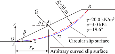
Fig. 2 Slope example 1
4.1 Effect of external load��s magnitude on slope stability
For the concentration force Q acting at point s1 on slope surface, ��=0�� and xp=10 m. The circular and arbitrary curved slip surfaces at the specific position in Example 1 were adopted. When the concentration force Q is equal to 0 kN, 25 kN, 50 kN, 75 kN, 100 kN, 125 kN and 150 kN, respectively, the results obtained using different methods are listed in Table 4.
Table 4 shows that: 1) the results of calculation mode I are close to those of the calculation mode II, with difference less than 5%; 2) the results calculated using the circular and arbitrary curved slip surfaces are the same to each other; and 3) compared with other calculation methods, Swedish and simplified Janbu methods have the smallest slope FOS.
4.2 Effect of external load��s action position and inclination angle on slope stability
For the concentration force acting at point s1 on slope surface, Q=75 kN, and xp=5 m, 10 m, and 15 m, respectively. The circular and arbitrary curved slip surfaces at the specific positions in Example 1 were adopted. The results obtained using different methods are listed in Table 5 for xp=10 m in the cases that �� is equal to 0��, 15��, 30��, 45��, 60��, 75��, and 90��, respectively, and the obtained normal and shear forces on slip surface are shown in Figs. 3-4 for ��=45�� and xp=10 m. In Figs. 3-4, the results of Spencer and M-P methods are nearly identical and shown using the same picture.
Table 5 and Figs. 3-4 show that: 1) the calculated Fs decreases gradually with the change of �� from 0�� to 90��; 2) with the increase of ��, the results of calculation mode I and mode II gradually become consistent to each other, and particularly when ��=90��, both have identical results.
4.3 Effect of external load��s different distribution patterns on slope stability
Different distribution patterns of external load on slope surface, listed in Table 3, were used in this example,and the circular and arbitrary curved slip surfaces at the specific position in Example 1 were also adopted. As shown in Fig. 5, the parameters of external loads are given as: Q=100 kN and xp=10 m for the concentration force; xp1=5.5 m, xp2=14.5 m and l1=9 m for the rectangular distribution load; xp1=4 m, xp2=13 m and l2= 9 m for the distribution load of triangle 1; xp1=7 m, xp2= 16 m and l3=9 m for the distribution load of triangle 2; xp1=5 m, xp2=14 m, l4=9 m and q41=0.5q42 for the distribution load of trapezoid 1; xp1=6 m, xp2=15 m, l5= 9 m and q52=0.5q51 for the distribution load of trapezoid 2. Assuming these distribution loads being equivalent with the concentration force, these distribution loads can be then determined according to the formulas in Table 3. When the inclination angles of external loads are all given to be equal to 90��-��, the results calculated using different methods are listed in Table 6, and the obtained normal and shear forces on slip surface are shown in Figs. 6-7 for the distribution load of trapezoid 2. In Figs. 6-7, the results of Spencer and M-P methods are also nearly identical and shown using the same picture.
Table 4 Contrast of slope FOS for different magnitudes of concentrated force
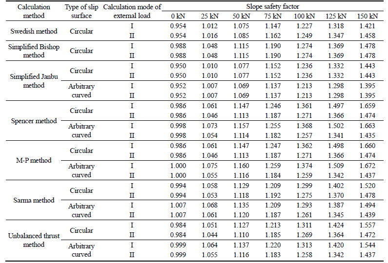
Table 5 Contrast of slope FOS for different inclination angles of concentrated force as xp=10 m
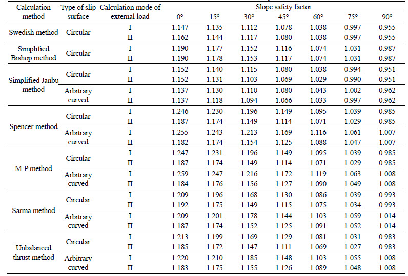
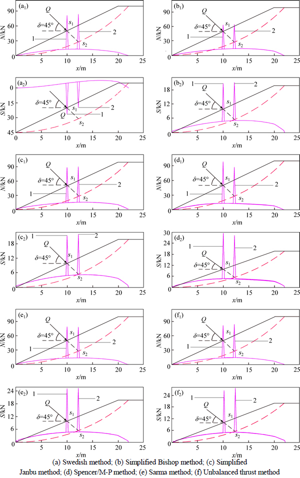
Fig. 3 Contrast of normal and shear forces on circular slip surface under two calculation modes of external load for Q=75 kN, xp=10 m and ��=45�� (1-Calculation mode I; 2-Calculation mode II):
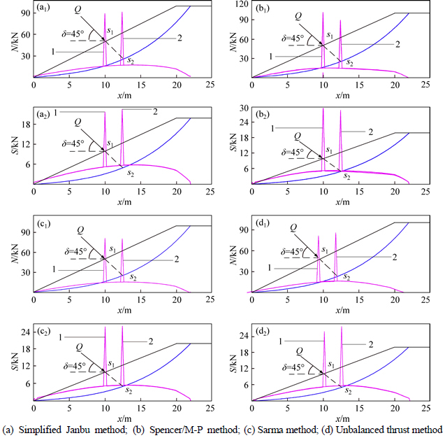
Fig. 4 Contrast of normal and shear forces on arbitrary curved slip surface under two calculation modes of external load for Q=75 kN, xp=10 m and ��=45�� (1-Calculation mode I; 2-Calculation mode II):
Table 6 and Figs. 6-7 show that: 1) the results calculated with calculation mode I are close to or smaller than those calculated with mode II; 2) if the external loads, including the concentration force and distribution loads, are equivalent to each other, the results of slope FOS under different external loads are consistent; 3) compared with the concentration force, the effect of distribution loads on the normal and shear forces is more obvious; 4) as it neglects the effect of inter-slice force,Swedish method has different shear force results from other methods in the stability analysis of slope under external loads.
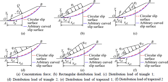
Fig. 5 Distribution patterns of external load on slope surface for slope example 1:
Table 6 Contrast of slope FOS for different distribution patterns of external load on slope surface
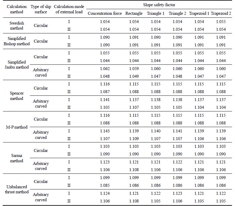
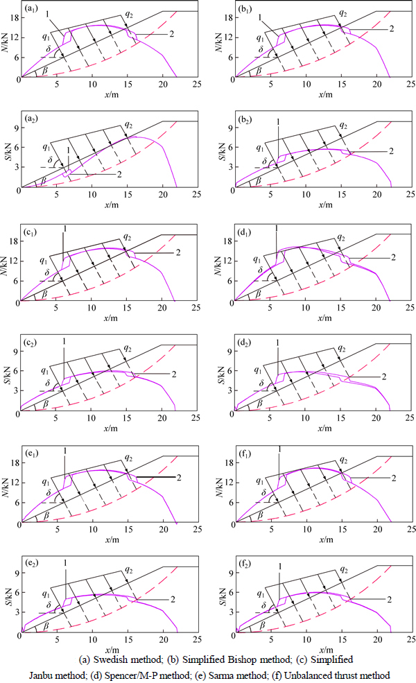
Fig. 6 Contrast of normal and shear forces on circular slip surface under two calculation modes of external load for distributed load of trapezoid 2 (1-Calculation mode I; 2-Calculation mode II):
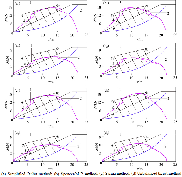
Fig. 7 Contrast of normal and shear forces on arbitrary curved slip surface under two calculation modes of external load for distributed load of trapezoid 2 (1-Calculation mode I; 2-Calculation mode II):
5 Stability analysis of slope under external loads
5.1 Homogeneous slope
Example 2 [19]: as shown in Fig. 8, slope height H=20 m with slope ratio=1:1.5, i.e., slope angle ��= 33.690��, and the soil parameters are given as: natural unit weight ��=18.82 kN/m3, cohesion c=41.65 kPa, and internal friction angle ��=15��. The xy-axes coordinate system was established by setting slope toe as the origin. The concentration force, rectangular distribution load, distribution load of triangle 2, and distribution load of trapezoid 2 were adopted in this example, and their parameters are given as: Q=200 kN and xp=10 m for the concentration force; xp1=0 m, xp2=20 m and l1=20 m for the rectangular distribution load; xp1=0 m, xp2=30 m and l2=30 m for the distribution load of triangle 2; xp1=0 m, xp2=22.5 m, l5=22.5 m and q52=0.5q51 for the distribution load of trapezoid 2. When the distribution loads have equivalent effect with the concentration force, the distribution loads can also be determined using the formulas in Table 3. The results calculated using different methods are listed in Table 7, for cases that the inclination angles of external loads are all equal to 90��-��.
Table 7 shows that the results of the minimum slope FOS of calculation mode I and II are quite close and their critical slip surface��s positions are identical as well, indicating that the obtained slope stability under external loads using these two modes have no difference to each other if the external loads on slope surface are equivalent.
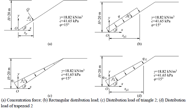
Fig. 8 Slope example 2:
Table 7 Contrast of minimum slope FOS for different distribution patterns of external loads in slope example 2
5.2 Heterogeneous slope
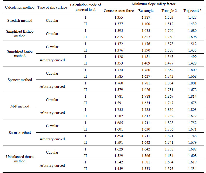
Example 3 [19]: as shown in Fig. 9, slope height H= 10 m with slope angle ��, slope ratio=1:2, and the soil parameters are given as: natural unit weight ��=19.5 kN/m3, cohesion c=0.0 kPa, and internal friction angle ��=38�� for soil #1; natural unit weight ��=19.5 kN/m3, cohesion c=5.3 kPa, and internal friction angle ��=23�� for soil #2; natural unit weight ��=19.5 kN/m3, cohesion c=7.2 kPa, and internal friction angle ��=20�� for soil #3. In this example, the concentration force, rectangular distribution load, distribution load of triangle 2, and distribution load of trapezoid 2 were adopted. The concentration forces include Q1, Q2, and Q3, and the x-coordinates of their action points on slope surface are xp1, xp2, and xp3, respectively. All distribution loads cover the entire slope surface, where the rectangular distribution load is equivalent with the concentration force, but only the resultant force of the distribution load of triangle 2, distribution load of trapezoid 2 is equal to that of the concentration force. For the concentration force, Q1=100 kN, Q2=100 kN, Q3=100 kN, xp1=5 m, xp2=10 m and xp3=15 m. Based on their equal resultant forces of the distribution load of triangle 2, distribution load of trapezoid 2, and concentration force, several relationship formulas can be obtained, including q1=Q1+Q2+Q3, q3l/2=Q1+Q2+Q3, and (q51+q52)l/2=Q1+Q2+Q3, where l is the length of the slope surface, and then the distribution loads can be determined using these formulas. According to the above given parameters, it can be known that the action positions of the external loads�� resultants from low to high are in turn given as: the distribution load of triangle 2, distribution load of trapezoid 2, rectangular distribution load, and concentration force. When the inclination angles of external loads are all assumed to be equal to 90��-��, the minimum FOS calculated using different methods are listed in Table 8.
Table 8 shows that: 1) for the minimum FOS, the result under the concentration force and rectangular distribution load is the smallest, and that under distribution load of triangle 2 is the largest, indicating that the external load has a greater effect on slope stability as the action point of its resultant force is closer to the lower sliding point of slip surface; 2) in the stability of slope under the rectangular distribution load and concentration force, their differences on the minimum FOS are about 3%, indicating that the stability results are also the same for the heterogeneous slope under external loads if these external loads are equivalent to each other; 3) in the heterogeneous slope, the differences on the minimum FOS calculated with two calculation modes of external load are about 1% for Swedish and simplified Bishop methods, whereas the differences of the results calculated with two calculation modes of external load are between 3% and 10% for simplified Janbu method, Spencer method, M-P method, Sarma method, and unbalanced thrust method. Meanwhile, the results calculated with mode II are smaller than those calculated with mode I.
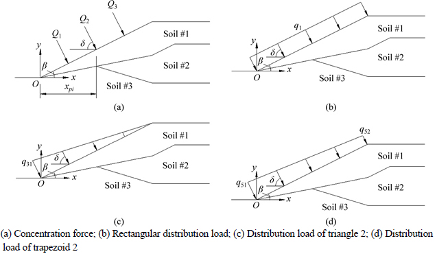
Fig. 9 Slope example 3:
Table 8 Contrast of minimum slope FOS for different distribution patterns of external load in slope example 3
6 Conclusions
External loads on slope surface have an important influence on slope stability. To assess the stability of slope under external loads, two calculation modes of external loads were considered, i.e., mode I in which the external load is thought to act on slope surface, and mode II in which the external load is thought act on slip surface along the force action line. Moreover, this work adopts four basic distribution patterns of the external load to study the effects of external load on slope stability, and complex external loads were composed of these basic patterns. Additionally, Swedish method, simplified Bishop method, simplified Janbu method, M-P method, Sarma method, and unbalanced thrust method were adopted to compare their differences. By parametric analyses, several conclusions can be obtained as follows:
1) With the large magnitude, small inclination angle, and action position being close to the slope toe, the effect of the external load on slope stability is more obvious.
2) The minimum slope FOS obtained with calculation mode II of external load is close to, but less than that obtained with calculation mode I, indicating that the results of two calculation modes has small differences on slope stability.
3) If the external loads on slope surface are equivalent, the slope stabilities under these external loads are similar to each other, and if the resultant force��s acting position for non-equivalent external loads is closer to the lower sliding point of slip surface, the effect of external load on slope stability is greater.
References
[1] SHU S Z, MUHUNTHAN B, BADGER T C, GRANDORFF R. Load testing of anchors for wire mesh and cable net rockfall slope protection systems [J]. Engineering Geology, 2005, 79(4): 162-176.
[2] SAGASETA C,  J. A general analytical solution for the required anchor force in rock slopes with toppling failure [J]. International Journal of Rock Mechanics and Mining Sciences, 2001, 38(3): 421-435.
[3] ALAMSHAHI S, HATAF N. Bearing capacity of strip footings on sand slopes reinforced with geogrid and grid-anchor [J]. Geotextiles and Geomembranes, 2009, 27(3): 217-226.
[4] LIU X M, CHEN C X, ZHENG Y, OU Z. Stability analysis of anchorage slope based on limit equilibrium theory [J]. Disaster Advances, 2012, 5(4): 892-895.
[5] GERMER K, BRAUN J. Effects of saturation on slope stability: Laboratory experiments utilizing external load [J]. Vadose Zone Journal, 2011, 10(2): 477-486.
[6] VANDENBERGE D R, DUNCAN J M, BRANDON T L. Limitations of transient seepage analyses for calculating pore pressures during external water level changes [J]. Journal of Geotechnical and Geoenvironmental Engineering, 2015, 141(1): 1-10.
[7] ZHANG K, CAO P, LIU Z Y, HU H H, GONG D P. Simulation analysis on three-dimensional slope failure under different conditions [J]. Transactions of Nonferrous Metals Society of China, 2011, 21(11): 2490-2502.
[8] FELLENIUS W. Calculation of the stability of earth dams [C]// Proc 2nd Congr 431 Large Dams. Washington, D.C, 1936, 445-462.
[9] BISHOP A W. The use of the slip circle in the stability analysis of earth slopes [J]. G��otechnique, 1955, 5(1): 7-17.
[10] JANBU N. Slope stability computations [M]// Embankment Dam Engineering, Casagrande Memorial Volume. HIRSCHFIELD E, POULOS S, Eds. New York: John Wiley, 1973: 47-86.
[11] SPENCER E. A method of analysis of the stability of embankments assuming parallel inter-slice forces [J]. Geotechnique, 1967, 17(1): 11-26.
[12] MORGENSTERN, PRICE V E. The analysis of the stability of general slip surfaces [J]. Geotechnique, 1965, 15(1): 79-93.
[13] SARMA S K. Stability analysis of embankments and slopes [J]. Journal of Geotechnical. Engineering, ASCE, 1979, 105(12): 1511-1524.
[14] ZHENG Y R, SHI W M, YANG M C. Discussion on imbalance thrust method and Sarma��s method [J]. Chinese Journal of Rock Mechanics and Engineering, 2004, 23(17): 3030-3036. (in Chinese)
[15] SANJAY K N, MONIRHOSSAIN M. Stability analysis of multi-directional anchored rock slope subjected to surcharge and seismic loads [J]. Soil Dynamics and Earthquake Engineering, 2011, 31(5): 841-844.
[16] AHMED A, UGAI K, YANG Q Q. Assessment of 3D slope stability analysis methods based on 3D simplified Janbu and Hovland methods [J]. International Journal of Geomechanics, 2012, 12(2): 81-89.
[17] ALKARNI A A, ALSHAMRANI M A. Study of the effect of soil anisotropy on slope stability using method of slices [J]. Computers and Geotechnics, 2000, 26(2): 83-103.
[18] JANUSZ K. Selected aspects of the stability assessment of slopes with the assumption of cylindrical slip surfaces [J]. Computers and Geotechnics, 2010, 37(6): 796-801.
[19] Rocscience Inc. Slide verification manual [R]. Toronto: Rocscience Inc., 2003: 8-118.
[20] DENG D P, LI L, ZHAO L H. A new method of sliding surface searching for general stability of slope based on Janbu method [J]. Rock and Soil Mechanics, 2011, 32(3): 891-898. (in Chinese)
(Edited by YANG Bing)
Foundation item: Project(2015M580702) supported by the China Postdoctoral Science Foundation; Project(51608541) supported by the National Natural Science Foundation of China; Project(2014122006) supported by the Guizhou Provincial Department of Transportation Foundation, China
Received date: 2015-04-15; Accepted date: 2015-09-30
Corresponding author: DENG Dong-ping, PhD; Tel: +86-13975150476; E-mail: dengdp851112@126.com
Abstract: Two calculation modes for the effect of external load on slope stability, i.e., mode I in which the external load is thought to act on slope surface, and mode II in which the external load is thought to act on slip surface along the force action line, were considered. Meanwhile, four basic distribution patterns of external load were used, of which complex external loads could be composed. In analysis process, several limit equilibrium methods, such as Swedish method, simplified Bishop method, simplified Janbu method, Spencer method, Morgenstern-Price (M-P) method, Sarma method, and unbalanced thrust method, were also adopted to contrast their differences in slope stability under the external load. According to parametric analysis, some conclusions can be obtained as follows: (1) The external load, with the large magnitude, small inclination angle, and acting position close to the slope toe, has more positive effect on slope stability; (2) The results calculated using modes I and II of external load are similar, indicating that the calculation mode of external load has little influence on slope stability; (3) If different patterns of external loads are equivalent to each other, their slope stability under these external loads are the same, and if not, the external load leads to the better slope stability, as action position of the resultant force for external load is closer to the lower sliding point of slip surface.
