
Trans. Nonferrous Met. Soc. China 22(2012) 2913-2924
Experimental study and numerical analysis on dry friction and wear performance of co-continuous SiC/Fe-40Cr against SiC/2618 Al alloy composites
JIANG Lan1, JIANG Yan-li2, YU Liang2, SU Nan1, DING You-dong1
1. Key Laboratory for Ecological Metallurgy of Multimetallic Mineral, Ministry of Education, Northeastern University, Shenyang 110819, China;
2. Key Laboratory of New Processing Technology for Nonferrous Metals & Materials, Ministry of Education, Guilin University of Technology, Guilin 543004, China
Received 9 October 2012; accepted 25 November 2012
Abstract:
The dry friction and wear behaviors of co-continuous composites SiC/Fe�C40Cr against SiC/Al 2618 alloy were investigated on a ring-on-ring friction and wear tester at sliding speed of 30-105 m/s under the load of 1.0-2.5 MPa. The experimental result reveals that the characteristic of two body abrasive wear and oxidation wear mechanisms are present for SiCn/2618 Al composite under higher load and sliding speed. SiC ceramic continuous network as the reinforcement can avoid composite from the third body wear that usually occurs in traditional particle reinforced composite. The mechanically mixed layer (MML) controls greatly the wear rate and friction coefficient of the composites. The composites tested at higher sliding speed exhibit higher value of friction coefficient and fluctuation, which is associated with the intermittent formation and removal of the MML. The wear and stress��strain behaviors of SiCn/Fe�C40Cr against SiCn/Al 2168 at 30-105 m/s under 1.0-2.5 MPa were analyzed by finite element method with the software Solidwork2012 Simulation, respectively. The wear and stress�Cstrain behavior of the composite predicted by the FEM correlated well with the experimental results.
Key words:
wear; SiC/Al 2618 alloy; SiC/Fe-40Cr; co-continuous composite; finite element method;
1 Introduction
Lightweight aluminum metal-matrix composites (Al-MMCs) brake disks instead of the traditional cast iron (steel) brake disks have been investigated with the aim of eventually saving energy consumption over the past several decades [1]. Different kinds and sizes of ceramic reinforcement particles, fibers or whiskers such as SiC, Al2O3, B4C, TiB2 and ZrB2 were widely chosen to fabricate desirable Al-MMCs rotors, whereas there are some unresolved technical difficulties [2-4]. These difficulties include lower mechanical properties, thermal capacity or friction levels compared to the cast iron (steel) [5,6]. Recently, the co-continuous metal�Cceramic composites (CCMCCs) have aroused extensive interest worldly, which are composed of soft metal and hard ceramics with three-dimensionally distributed network structure, can provide the desirable mechanical properties including high specific stiffness, high plastic flow strength, creep resistance, good oxidation and corrosion resistance [7-10]. They have potential applications in the dry friction and wear applications [11,12], especially have been applied in the brake system for high-speed trains [13,14]. CCMCCs can be obtained by several techniques, in particular by standard infiltration over porous preforms [15,16], by hot pressing [17] or by reactive infiltration over dense preforms, known as reactive metal penetration (RMP) [18].
It is known that the brake disks�� primary function is to dissipate mechanical energy by converting it into heat during the braking process without experiencing damages in structure and deterioration in property [19]. Especially, with increasing the trains speed to 300-380 km/h, these materials of brake disk suffer from several problems including adhesion, over abrasion, fatigue fracture and flake spalling [20]. The abrasive wear is characterized by cutting, grooving, plastic fatigue and cracking processes, which is usually divided into two types: two-body abrasion and three-body abrasion. The former is caused by hard protuberances or embedded hard particles sliding on the counter surface, while during the latter process hard particles can move freely between the contacting surfaces. The rate of material removal in three-body abrasion can be one order of magnitude lower than that in the two-body abrasion since the free rolling of the hard particles greatly mitigates attacks on the counter surface [21]. HUANG et al [22] revealed that the co-continuous SiC/7075 Al alloy composites (SiCn/7075) reduced the wear rate from the matrix alloy at all loading conditions because the CCMCCs could avoid the reduction of wear resistance raised from the separation of un-continuous reinforcement from the matrix at high temperature. CREE and PUGH [23] reported that the A356/SiC foam interpenetrating phase composite had good wear behaviors and could be used in light-weight applications where moderate strength and wear properties are needed. ZHANG and FENG [24] reported that when the phenolic resin brake pad dry slid against the CCMCCs, the pad two-body abrasion predominated over its three-body abrasion in determining the friction and wear. Although SiCn/Al composites are attractive candidates for high performance wear resistance applications, the number of investigations is still limited and, in most cases, the mullite or SiO2 or Si bonded porous SiC ceramics were used as the reinforcements, which have lower strength compared to that of the pure porous SiC ceramic, and should decrease the wear performance of SiCn/Al alloy composites compared to that of higher strength pure porous SiC structure reinforced Al composites [25-27]. Moreover, the friction behaviors and wear mechanism of the SiCn/Al composites contacting with different friction counterparts under heavy load at high braking speed are still not clear [28]. The aim of the present study is to understand the friction and wear behaviors of the friction pairs consisting of pure porous SiC reinforced Fe-40Cr alloy composite (SiCn/Fe-40Cr) against SiCn/2618 Al alloy composite. In this paper, the SiCn/2618 CCMCCs were prepared by infiltration of a molten 2618 Al alloy with multi-element addition (Ti, rare earth elements) which has good heat-resistant property in order to meet the request for brake material application at speeds above 350 km/h, into the pure porous SiC ceramic under pressure with vacuum-pressure casting process (VPCP) method patented by RU et al [29]. The dry friction and wear properties, such as friction coefficient, wear depth, wear surface and sub-surface micrographs of the composites were illustrated. Moreover, the wear behavior was simulated with the help of finite element calculation software Solidwork2012 Simulation.
2 Experimental
2.1 Sample preparation
The SiCn/2618 composites were prepared by VPCP method. 6h-SiC and ��-SiC powders (purity 99%, d50=1.5 ��m) from Tangshan Hexagon Co., Ltd., Hebei Province, China, were first prepared into aqueous slurry. A porous polyurethane was used as a template to produce SiC preform. The template was submerged into the SiC slurry and then was taken out to dry at room temperature for 24 h to form the SiC green pattern, which was then sintered at 1950-2050 ��C for 0.5-1 h in a graphite resistor furnace, with argon gas as the sintering atmosphere to prepare the porous SiC preform. Then the SiC particles were sintered to be a rigid ceramic network structure. The porous SiC preform was heated at 1200 ��C for 4 h in a stationary air ambient, then SiO2 thin film was formed on the SiC structure. The SiCn/2618 composite was prepared via casting the liquid 2618 Al alloy (2.25% Cu, 1.60% Mg, 1.10% Fe, 1.15% Ni, 0.20% Ti, 0.3% Y, balance Al) from Youhua Aluminum Group Corporation, Jiangsu Province, China, into the oxide porous SiC ceramics in a special home-made vacuum-pressure furnace at 750 ��C by pressure, caused by pressure difference between pressured gas and vacuum. The Al interpenetrated the porous SiC ceramic and formed the composites.
SiCn/Fe�C40Cr was also prepared by VPCP method. The molten Fe�C40Cr alloy (14.00% Cr, 1.00% Si, 0.003% S, 0.035% P, 1.00% Mn, 0.25% C, balance Fe) from Anshan Iron and Steel Group Corporation, Anshan, Liaoning Province, China, was cast into the oxide porous SiC ceramic. The porous SiC ceramic was preheated to 450 ��C in vacuum prior to steel infiltration. Ingot of Fe-40Cr was melted in a vacuum furnace at 1700 ��C and the molten steel was then poured into the pre-heated porous SiC ceramic for infiltration. The infiltrated composite was allowed to solidify and cool down naturally in the vacuum furnace. The processing of preparing composites was described in detail in Ref. [5].
2.2 Characterizations of materials
2.2.1 Phase composition and microstructure
The samples were crushed into powders and analyzed by X-ray diffraction (XRD), via a computer-controlled diffractometer (PANALYTICL B.V/PW3040/60, Netherlands) with Cu K�� radiation at 40 kV and 100 mA. Data were digitally recorded in a continuous scanning mode in the angle (2q) range of 10��-90�� with a scanning rate of 0.02 (��)/s. The microstructure of the composites was characterized using optical metallographic (OM, GX71, Olympus, Japan), and scanning electron microscopy (SEM, SSX-505, Shimadzu, Japan) at 15 kV and 10 mA. The element composition analysis was conducted by energy- dispersive X-ray spectrometer (EDS). For investigating the friction and wear mechanism of SiCn/Fe�C40Cr against SiCn/2618, the worn surface was observed with SEM after 30 min ultrasonic cleaning to remove most of debris attached on the worn surface. The wear depth in worn region was measured by laser co-focusing electron microscopy.
2.2.2 Friction and wear properties
Friction and wear property testing of the samples was performed on a ring-on-ring MM1000II�Ctype machine (Xi��an ShunTong Technical Research Institute, Shanxi Province, China) as shown in Fig. 1 at room temperature. The wear specimens were machined from the SiCn/2618 composites in the form of ring with the outer diameter of 75 mm, the inner diameter of 53 mm, and the thickness of 10 mm as the rotating brake disk. The counterpart stationary rings were made of SiCn/Fe�C40Cr composites as brake pad. During the tests, the initial-mass disk of 0.20 kg��m2 was rotated up to 6500 r/min before each braking, then a fixed pressure of 1.0, 1.5, 2.0, and 2.5 MPa was applied through the gas pressure feeder at the sliding speed of 30, 45, 60, 75, 90, and 105 m/s. Sliding speed means the linear velocity of the outer edge of the rotating disk. The number of repeated tests under the applied loads of 1.0-2.5 MPa is 50. The rotating speed of the initial-mass disc was reduced rapidly due to the friction force between the SiCn/2618 ring and the counterpart SiCn/Fe�C40Cr ring. During the process, the torque value was recorded by the computer and consequently the friction coefficient was calculated. The temperature of the samples during braking was on-line measured using chromel-alumel thermocouple probe with a stainless steel sheath (diameter=0.40 mm), which was embedded in a hole of 2 mm in diameter, 7 mm in depth and beneath 1.5 mm of wear surface of the SiCn/Fe�C40Cr stationary ring. The specimens were thoroughly cleaned with acetone in ultrasonic cleaner before and after the wear test, and were weighed before and after each test to measure the change in mass for wear rate calculation. The mass loss during the wear test was measured using a photoelectric balance with the resolution of ��0.1 mg. The stable friction coefficient, S, during each braking test can be calculated from
 (1)
(1)
where mmax is the maximum friction coefficient (COF) during each braking test, and mcp is the average COF, which is automatically recorded by the computer of the testing machine.
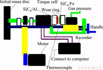
Fig. 1 Schematic of testing configuration of MM1000II�Ctype ring-on-ring machine
3 Results and discussion
3.1 Microstructure and phase composition
Figure 2 shows the micrograph of SiC preform before molten Fe-40Cr steel infiltration. The pores are similar hexagonal holes, interconnected and uniform in size and distribution. The porosity of the SiC preform measured by mercury porosimetry is 45% (volume fraction), with average pore diameter of 2-3 mm and average pore wall thickness of about 0.8 mm. Figure 3 shows the ring of the SiCn/Fe-40Cr for test in our experiment. The dark phase is the SiC network structure and the lighter contrast is the infiltrated Fe-40Cr steel.
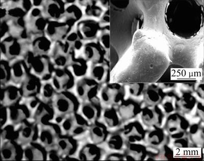
Fig. 2 Micrograph of porous SiC perform before infiltration
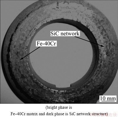
Fig. 3 Ring of SiCn/Fe�C40Cr composite for test
Figure 4 shows the detailed microstructures of the SiCn/Fe-40Cr composite. Figure 4(a) shows an optical image containing four distinctive sections, labeled I, II, III and SiC. Figure 4(b) shows an optical image of the structure in section I. The structure contains ferrite Fe(Si) solid solution matrix and graphite rosette flakes. The average width of section I is 80 ��m. Figure 4(c) shows an optical image of the structure in section II. The structure is pearlite. The average width of section II is about 180 ��m. Figure 4(d) shows an optical image of the structure in section III. It contains a continuous ferrite matrix and scattered colonies of pearlite. The average width of section III is about 250 ��m. It is also evident that a narrow gap of 40-50 ��m in width exists between SiC and region I. This is caused by the solidification shrinkage of the steel and the difference in thermal expansion coefficients between SiC and the steel, which are 4.6��10-6 ��C-1 and 1.2��10-5 ��C-1, respectively.
Figure 5 shows XRD spectrum of the SiCn/Fe�C40Cr composite. The composite is mainly composed of SiC, Fe, Cr7C3, Cr23C6, and Fe-C composite. It is known that in a dry atmosphere of high oxide partial pressure (e.g. ambient air), the oxidation of SiC is passive and described as follows:
2SiC(s)+3O2(g)��2SiO2(s)+2CO(g) (2)
SiO2 thin film is formed on the SiC structure after being heated in our experiment. The interface structure of the oxidized-SiC/Fe-40Cr composite is of SiC/SiO2/ Fe-40Cr theoretically. Figure 6 shows the line scanning analysis of the interface of the oxidized-SiC/Fe-40Cr composite. It is noted that O element is not found in the composite. It means that the SiO2 thin film is destroyed by the reaction of Fe and SiC. The interface reaction between the SiC and Fe�C40Cr is prevented or effectively hindered by the SiO2 thin film. As a result, the interfacial microstructure and properties of the composites are improved. Compared to the result in Ref. [30], the average width of section I decreased from 230 ��m to 80 ��m.
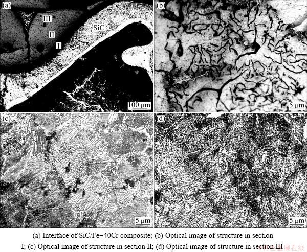
Fig. 4 Microstructures of SiCn/Fe�C40Cr composite
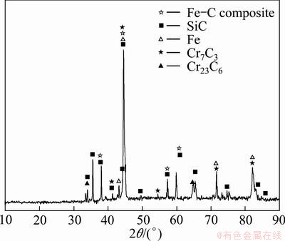
Fig. 5 XRD pattern of SiCn/Fe�C40Cr composites
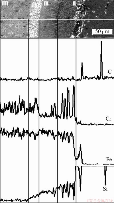
Fig. 6 Line scanning analysis of primary elements in interface of SiCn/Fe�C40Cr composite
Figure 7(a) shows the typical micrographs of the co-continuous SiCn/2618 Al composites, where the brighter phase is Al and the darker is SiC. Figure 7(b) shows the microstructure of interface of SiCn/2168 Al composite, from which it can be seen that the molten alloy was completely infiltrated into the foams. The density measurements showed that the density of composites is >99% of the theoretical one. The appearance of the phases suggests that these microstructures are in agreement with the co-continuous SiC/Al micro constituent described in the articles mentioned in the introduction. But in this work, their morphology is finer as rare earth elements Y were used to decrease the surface tension and enhance the wetting of ceramic materials. From the micrographs, no bulk second phases could be observed in the composites in Fig. 7(b), but a thin film may be seen at localized positions on the Al grain boundaries in the infiltrated SiC preform. Line scanning analysis (Fig. 7(c)) suggested that there were SiO2 films. It shows good interfacial bonding with a continuous SiO2 layer, 100-400 nm in thickness, formed at the Al-SiC interface [31].
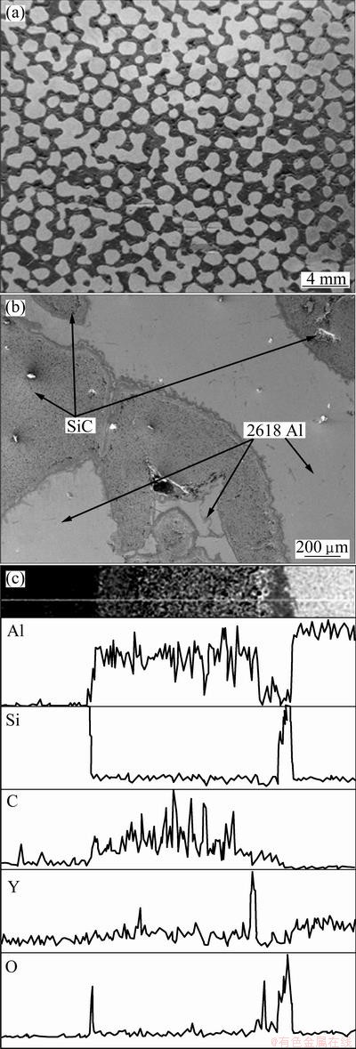
Fig. 7 Micrograph of SiCn/2618 Al composite (a), microstructure of interface of SiCn/2618 Al composite (b), line scanning analysis of primary elements in interface (c)
3.2 Friction coefficient
Figure 8 shows the mean COF of SiCn/Fe-40Cr composites against SiCn/2618 Al composites on a ring- on-ring friction and wear tester at a sliding speed of 30-105 m/s under the load (braking pressure) of 1.0-2.5 MPa. It can be found that in lower sliding speed cases (30, 45, 60 and 75 m/s), the mean COF goes down with the load increasing, while in higher sliding speed cases (90 and 105 m/s), the mean COF ascends after the short descending. Generally, friction coefficient is inversely proportional to the load. It can be seen that the mean COF of composites reduces from 0.31 to 0.24 at 30 m/s with the imposed load increasing from 1.0 MPa to 2.5 MPa. As for other sliding speeds at 45, 60, 75 m/s, the mean COF reduces from 0.29 to 0.22, 0.27 to 0.23, and 0.25 to 0.20, respectively. However, the mean COF reduces from 0.23 to 0.19 with the load increasing from 1.0 MPa to 2.0 MPa, but it increases to 2.2 under load of 2.5 MPa at 90 m/s. A similar trend was seen at the speed of 105 m/s.
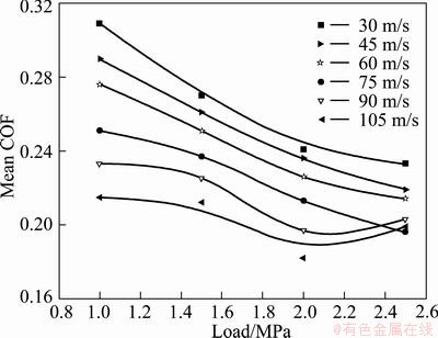
Fig. 8 Relationship between mean COF and braking pressure as well as speed
Figure 9 shows the relationship between stable friction coefficient and the braking pressure as well as the sliding speed. From Fig. 9, it can be seen that the stable friction coefficient decreased with increasing the load from 1.0 MPa to 2.5 MPa at lower braking speed (30, 45, and 60 m/s), however, and the stable friction coefficient increased with increasing the load at higher braking speed (75, 90, and 105 m/s). The reason is that the abrasion in low braking speed and low pressure is abrasive grain wear, namely three-body abrasion [32,33]. The spalled pieces were squeezed and rolled on the friction surface, leading to the weak COF stability. However, with the increasing rolling speed and load, the adhesive wear became the main abrasion instead of the grain abrasion, namely two-body abrasion [34]. It is supposed that SiC structure is able to support the load applied on the sliding surface and to restrict the plastic deformation and high temperature softening of the Al alloy matrix, thus the composites show greatly improved wear-resistance under higher load [35].
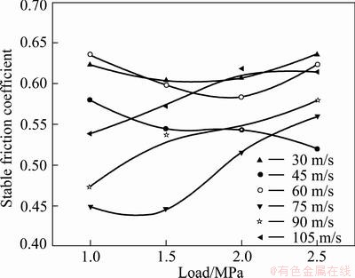
Fig. 9 Relationship between stable friction coefficient and braking pressure as well as sliding speed
3.3 torque curves
The variation curves (Fig. 10) of torque of the SiCn/ Fe�C40Cr composites against SiCn/2618 Al composites at different braking speeds under loads of 1.0-2.5 MPa show the similar tendency. That is, at lower braking speed, the samples showed a persistent increase of the torque. When the braking speed exceeded 75 m/s, the torque curve exhibited a ��saddle�� shape, namely a relatively smooth middle stage, which was also observed in friction and wear behaviors of C/C�CBN composites reported by FAN et al [36]. It can be found that a sharp peak appeared at the end of the curve, which means the torque reached the highest value at the end of braking.
3.4 Wear behavior
3.4.1 wear rate
Figure 11 shows the variation of the wear rate of the SiCn/2618 Al composites under the applied load at different sliding speed. As the velocity increased the wear rate also increased. This may be due to the quick plastic deformation of material at surfaces and subsurfaces when it is subjected to the sliding wear. At higher speeds temperature increased and thermal softening of matrix led to more wear rate. From Fig. 11, the wear rate increased steeply with increasing the applied load. Further, the size of the wear debris increased with increasing the loads resulting in large wear loss at higher loads. Among the three parameters, SiC structure reinforcement, sliding velocity and load, the sliding velocity has relatively little effect on the sliding wear rate, and the load has the highest effect on the sliding wear rate [32-35].
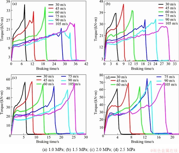
Fig. 10 Relationship between torque and braking pressure as well as sliding speed
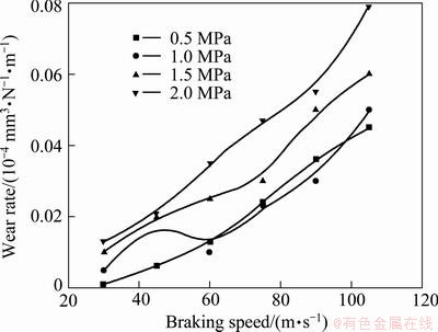
Fig. 11 Relationship between wear rate and braking pressure as well as sliding speed
3.4.2 Morphology of worn surface
Figure 12 shows the worn surface morphology at sliding speed of 105 m/s under the load of 1.0-2.5 MPa, in which the sliding directions (SD, arrow direction) are indicated. Figure 12(a) depicts the worn surface tested under the load of 1.0 MPa. Obvious parallel grooves were observed due to the abrasion of the exposed SiC structure. This process is referred to microcutting. The average wear groove width for the 1.0 MPa test is 3-5 ��m. It can be seen that even after ultrasonic cleaning with acetone, there are still a great deal of white SiC powders retained on the worn surface. Such powders are initiated by ploughing out from both the lower and upper counterfaces of the specimens during friction, and it is very possible for them to be embedded into worn surface again. Then the wear grooves can still be distinguished. Namely, it is three-body wear under lower load. Figure 12(b) depicts the worn surface of the disc tested under load of 1.5 MPa. It is found that the Al alloy in the composites was smeared out of the SiC cells and elongated along the sliding direction. Then the mechanically mixed layer (MML) was formed. It is noted that the composition of the debris is similar to that of the MML, indicating that the debris are essentially formed out of the MML layer. This observation is in accordance with the high value of friction coefficient and small fluctuation shown in Fig. 8. So it can be concluded that the composites tested at high sliding speed exhibit high value of friction coefficient and intense fluctuation, which is associated with the intermittent formation and removal of the MML. Figure 12(c) shows the worn surface tested under load of 2.0 MPa. The wear grooves show the evidence of severely plastic flow in the form of grooves parallel to the sliding direction. The damage to the MML is aggravated by the severe plastic deformation of the counterface. The abrasive particles penetrate into a shallow surface layer of the composite under higher load. The average wear groove width is over 8 ��m. There is no SiC particles resulting from SiC structure breakage observed on the worn surfaces. The wear mechanism is due to the fact that the SiCn/2618 Al can change the friction transition of three-body abrasion to two-body abrasion under 2.0 MPa. With the applied load of 2.5 MPa (Fig. 12(d)), the quantity of particles embedded is increased [21-24]. The worn counterface of the composite sample shows shallow unidirectional grooves conforming to the applied two-body abrasive wear conditions. Moreover, the white particles are rich in Al and O by EDAX analysis (Fig. 13). Namely, the oxidative wear can occur as well. It is revealed that the wear mechanism for SiCn/2618 Al composite is characteristic of two-body abrasive wear and combination of abrasive wear, oxidation wear and plastic deformation under load of 2.5 MPa.
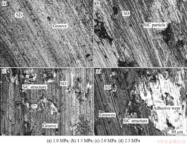
Fig. 12 Worn counterface morphologies of SiCn/2618 Al at sliding speed of 105 m/s under different loads
3.4.3 Wear depth
Figure 14 shows the wear depth of SiCn/2618 Al composite under load of 2.5 MPa at speeds of 90 and 105 m/s. It can be found that the mean wear depth of the composite at 90 m/s is 300-360 ��m (Figs. 14(a) and (c)). The feathers of the worn surface of the counterface can help to explain the variation of the friction coefficient. The friction coefficient is found to be correlated with the formation and fracture of the MML on the counterface of the composite. If the worn counterface is relatively smooth (the wear depth is 80-100 ��m at 105 m/s, Figs. 13(b) and (d)), the fluctuation of friction coefficient will be reduced and the stable friction coefficient will be increased as well (Fig. 9). Once the MML fractured, intense fluctuation of friction coefficient was observed. The large fluctuation of friction coefficient in Fig. 8 agrees well with the feather of the worn surface (Figs. 12(a) and (c)).

Fig. 13 EDAX analysis of point A in Fig. 12(d)
3.4 FEM simulation of wear behavior
A simple two-phase-interpenetrating unit geometry was used to represent the material Fe-40Cr or 2618 Al alloy filling the SiC structure. The properties of SiC structure were defined as elastic modulus 450 GPa, Poisson ratio 0.10, density 3.15 g/cm3, ��b=200 MPa, shear modulus 192 MPa. The properties of Fe-40Cr matrix were defined as elastic modulus 240 GPa, Poisson ratio 0.34, density 7.8 g/cm3, ��b =800MPa, ��s =540 MPa, shear modulus 450 MPa. The properties of 2618 Al alloy matrix were defined as elastic modulus 66 GPa, Poisson ratio 0.32, density 2.7 g/cm3, ��b=265 MPa, ��s=182 MPa, shear modulus 175 MPa. We simulated the wear and stress�Cstrain behavior of the SiCn/Fe-40Cr against SiCn/2618 Al composite at sliding speed of 30-105 m/s under the load range of 1.0-2.5 MPa to know the wear mechanisms. The load was applied on the top face of the unit in the z-direction. The xy and yz planes were constrained (green points) and the opposite plane was required to displace as planes during deformation by load (z direction arrows) and shear force (x direction arrows), as shown in Fig. 15 (b, c). The perfect bonding between the two phases was assumed in the model. The Fe-40Cr and 2618 Al alloy behaved in an elastic perfectly-plastic manner, while SiC structure was modeled as an isotropic fully elastic solid.

Fig. 14 Measured wear depth of worn surface of SiCn/2618 Al at speeds of 90 m/s (a, c) and 105 m/s (b, d) under 2.5 MPa
Figure 15 shows the simulation of wear behavior on the counterface. One of the distinguishing characteristics of Al-based composite reinforced by three-dimensional (3D) continuous network SiC is the structure distributing continuously in 3D space. The load would be borne and transferred through the whole frame of reinforcement. So it attributes to the characteristic of two body abrasive wear [32,34]. Our simulation results show that the maximum stress occurred at the interfacial boundary between SiC structure and Fe�C40Cr and 2618 Al matrix. This is caused due to the three-dimensional co-continuous structural characteristic. The force applied on each rib affects the other adjacent rib. For a low load of 1.0 MPa, the SiC structure penetration depth is shallow such that a small plastic deformation has occurred (Fig. 14(a)). The composite two- and three-body abrasions are relatively weak. For a load of 1.5 MPa, bulk ceramic blocks seem to have been penetrated with the exception of the smaller ceramic protuberances. A large recess is found in Fig. 15(b). The number of the shallow grooves is reduced in comparison with that in Fig. 15(b). This is because the pad three-body abrasion destroyed some small plateaus and a part of grooves were filled with the MML. For a higher load of 2.0 MPa, the ceramics were penetrated more deeply to induce significant plastic deformation (Fig. 15(c)). A larger recess, deeper grooves and fewer micro-cracks are clearly observed [37]. For a maximum load of 2.5 MPa, micro- and macro-cracks and dramatic surface damage are predominant features (Fig. 15(d)). The wear mechanism is that the SiCn/2618 Al can change the friction transition of three-body abrasion to two-body abrasion under 2.0 MPa. The maximum stress in Fe�C40Cr matrix is 235 MPa, and in 2618 Al matrix is 220 MPa. The maximum strain in Fe�C40Cr matrix is 9.9��10�C6 mm, and in 2618 Al matrix is 3.3��10�C5 mm. Additionally, it should be noted that even the destruction of SiC structure occurs, the large SiC particles separated from the SiC structure are still difficult to be ploughed out or delaminated away from the surface by small abrasive particles in composites reinforced by 3D continuous reinforcement [38]. The scoring tracks pass through the recesses (Figs. 15(a) and (b)), further confirming our simulated result. The wear behavior of the composite predicted based on the Solidwork Simulation by the 3D model of microstructure correlated very well with the experimental results.
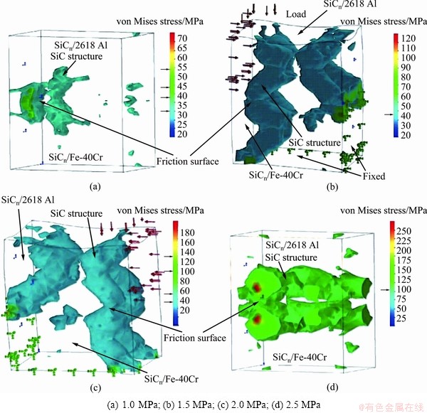
Fig. 15 simulation of wear behavior of SiCn/Fe�C40Cr composites against SiCn/2618 Al composites at different load
Figure 16 shows the measured and predicted COF and temperature at friction surface of SiCn/Fe�C40Cr ring at speed of 30-105 m/s under load of 1.0-2.5 MPa. It can be seen that the experimental results are very similar to those obtained by numerical simulation. It is observed that the temperature obtained by simulation reaches the maximum of 487 ��C under 2.5 MPa, while the experimental data comes up to the maximum of 512 ��C. The simulated COF is 0.2 at 105 m/s under 2.5 MPa. The measured COF is 0.25 under the same condition. The agreement between the measured and predicted temperature is good. However, the predicted COF value is lower than the measured value. The reason should be studied more deeply in the future.
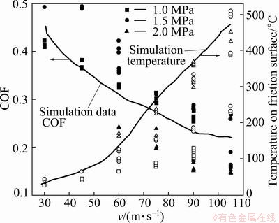
Fig. 16 Measured and predicted COF and temperature at friction surface of SiCn/Fe�C40Cr ring at speed of 30-105 m/s under load 1.0-2.5 MPa
4 Conclusions
The friction and wear behaviors of the SiCn/ Fe-40Cr composites against SiCn/2618 Al composite were investigated on a ring-on-ring friction and wear tester at a sliding speed of 30-105 m/s under load of 1.0 -2.5 MPa.
1) SiCn/Fe�C40Cr composite is mainly composed of SiC, Fe and Fe-C composite and Cr-C composite phases, and the microstructure contains four distinctive sections.
2) The density of SiCn/2618 Al composite is >99% of theoretical density. A good interfacial bonding with a continuous SiO2 layer, 100-400 nm in thickness, forms at the Al-SiC interface.
3) The friction and wear behavior of SiCn/Fe�C40Cr composites against SiCn/2618 Al composite has characteristics of abrasive wear, oxidation wear and two body wear under high load of 2.0-2.5 MPa, however, under lower load of 1.0-1.5 MPa, the characteristic of friction and wear behavior is three body wear.
4) The mechanically mixed layer (MML) controls greatly the wear rate and friction coefficient of the composites. The composites tested at high sliding speed exhibit high value of friction coefficient and fluctuation, which is associated with the intermittent formation and removal of the MML.
5) 3D continuous network SiC ceramic as the reinforcement of Al based composite can avoid the third body wear. SiC interpenetrating continuous network structure leads to the symmetry distribution of stresses. The wear behavior of the composite predicted based on the Solidwork Simulation by the 3D model of microstructure correlated well with the experimental results.
References
[1] SANNINO A P, RACK H J. Dry sliding wear of discontinuously reinforced aluminum composites: Review and discussion [J]. Wear, 1995, 189: 1-16.
[2] SUDARSHAN, SURAPPA M K. Dry sliding wear of fly ash particle reinforced A356 Al composites [J]. Wear, 2008, 265(3-4): 349-360.
[3] CHO K H, JANG H, HONG Y S, KIM S J, BASCH R H. The size effect of zircon particles on the friction characteristics of brake lining materials [J]. Wear, 2008, 264(3-4): 291-297.
[4] KUMAR G N, NARAYANASAMY R, NATARAJAN S, BABU S P K, SIVAPRASAD K, SIVASANKARAN S. Dry sliding wear behaviour of AA 6351-ZrB2 in situ composite at room temperature [J]. Materials & Design, 2010, 31(3): 1526-1532.
[5] YU L, JIANG Y L, RU H Q, LIU J T, LUO K. Microstructures of co-continuous SiC/Fe-2Cr13 composite fabricated by vacuum- pressure casting and infiltration processes [J]. Advanced Materials Research, 2011, 239-242: 1661-1664.
[6] TANG W M, ZHENG Z X, DING H F, JIN Z H. The interfacial stability of the coated-SiC/Fe couple [J]. Materials Chemistry and Physics, 2003, 77(1): 236-241.
[7] CHANG H, BINNER J, HIGGINSON R, MYERS P, WEBB P, GUS K. High strain rate characteristics of 3�C3 metal�Cceramic interpenetrating composites [J]. Materials Science and Engineering A, 2011, 528: 2239-2243.
[8] ZHANG S Y, LI Y Y, QU S G, CHEN W P. Friction and wear behaviour of brake pads dry sliding against semi-interpenetrating network ceramics/Al-alloy composites [J]. Tribology International, 2010, 38: 135-145.
[9] SCHERM F,  R, NEUBRAND A, BOSBACH F, GLATZEL U. Mechanical characterisation of interpenetrating network metal�C ceramic composites [J]. Materials Science and Engineering A, 2010, 527: 1260-1265.
[10] CHANG H, BINNER J, HIGGINSON R. Dry sliding wear behaviour of Al(Mg)/Al2O3 interpenetrating composites produced by a pressureless infiltration technique [J]. Wear, 2010, 268(1-2): 166-171.
[11] MANFREDI D, PAVESE M, BIAMINO S, ANTONINI A, FINO P, BADINI C. Microstructure and mechanical properties of co-continuous metal/ceramic composites obtained from reactive metal penetration of commercial aluminium alloys into cordierite [J]. Composites Part A, 2010, 41: 639-645.
[12] CHEN M Y, BRESLIN, M C. Friction behavior of co-continuous alumina/aluminum composites with and without SiC reinforcement [J]. Wear, 2002, 249: 868-876.
[13] YU L, JIANG Y L, LU S K, RU H Q, FANG M. FEM for brake discs of SiC 3D continuous ceramic reinforced 7075 aluminum alloy for CRH3 trains applying emergency braking [J]. Applied Mechanics and Materials, 2012, 120: 51-55.
[14] JIANG L, JIANG Y L, YU L, SU N, DING Y D. Thermal analysis for brake disks of SiC/6061 Al alloy co-continuous composite for CRH3 during emergency braking considering airflow cooling [J]. Transactions of Nonferrous Metals Society of China, 2012, 22: 2783-2791.
[15] MATTEO P, MASSIMILIANO V, CLAUDIO B. Effect of porosity of cordierite preforms on microstructure and mechanical strength of co-continuous ceramic composites [J]. Journal of the European Ceramic Society, 2007, 27: 131-141.
[16] JOHNSON D F, CARTER E A. Bonding and adhesion at the SiC/Fe interface [J]. J Phys Chem A, 2009, 113: 4367-4373.
[17] ZHU H X, ABBASCHIAN R. In-situ processing of NiAl�Calumina composites by thermite reaction [J]. Materials Science and Engineering A, 2000, 282: 1-7.
[18] DIEGO M, MATTEO P, SARA B, PAOLO F, CLAUDIO B. NiAl(Si)/Al2O3 co-continuous composites by double reactive metal penetration into silica preforms [J]. Intermetallcs, 2008, 16(4): 580-583.
[19] KIM S S, HWANG H J, SHIN M W, JANG H. Friction and vibration of automotive brake pads containing different abrasive particles [J]. Wear, 2011, 271: 1194-1202.
[20]  I, PRIETZEL C, ROOCH H,
  A L, DEGALLAIX G, DESPLANQUES Y. A comprehensive microscopic study of third body formation at the interface between a brake pad and brake disc during the final stage of a pin-on-disc test [J]. Wear, 2009, 267(5-8): 781-788.
[21] SURESHA B, CHANDRAMOHAN G, SIDDARAMAIAH, SAMAPTHKUMARAN P, SEETHARAMU S. Three-body abrasive wear behaviour of carbon and glass fiber reinforced epoxy composites [J]. Materials Science and Engineering A, 2007, 443: 285-291.
[22] HUANG D, CHEN W P, ZHANG S Y, HE Z X. Dry friction and wear performance of SiC 3D continuous ceramic frame reinforced 7075Al alloy [J]. Transactions of Nonferrous Metals Society of China, 2010, 20(1): 54-58.
[23] CREE D, PUGH M. Dry wear and friction properties of an A356/SiC foam interpenetrating phase composite [J]. Wear, 2011, 272(1): 88-96.
[24] ZHANG S Y, FENG S S. Friction and wear performances of brake material dry sliding against a composite with a semi-interpenetrating network structure of ceramics and Al-alloy [J]. Tribology International, 2011, 44: 248-257.
[25] ZHANG S Y, XUE A J, JIN X F, CHEN W P, LI Z G, LIU Y P, WANG H B. An experimental investigation of semi-interpenetrating network ceramic skeleton-reinforced Al-alloy composites dry sliding against Cr12 die steel [J]. Tribology Letter, 2012, 45: 29-36.
[26] PAVESE M, FINO P, UGUES D, BADINI C. High cycle fatigue study of metal-ceramic co-continuous composites [J]. Scripta Materialia, 2006, 55: 1135-1138.
[27] PAVESE M, VALLE M, BADINI C. Effect of porosity of cordierite performs on microstructure and mechanical strength of co-continuous ceramic composites [J]. Journal of the European Ceramic Society, 2007, 27: 131-141.
[28] GLENN S D, BRESLIN M C. Co-continuous composite materials for friction and braking applications [J]. Journal of the Minerals, Metals and Materials Society, 2006, 58(11): 87-92.
[29] RU H Q, FANG M, WANG R Q, ZUO L. A method of fabrication metal-ceramic friction composite with vacuum-pressure casting process. CN200510046691 [P]. 2005-6-16.
[30] RU H Q, LI J Y, WANG W. 3D network SiC-metals composites for heavy duty brake applications [C]// Metal, Ceramic and Polymeric Composites for Various Uses. Croatia: InTech, 2011.
[31] GUL F, ACILAR M. Effect of the reinforcement volume fraction on the dry sliding wear behaviour of Al�C10%Si/SiCp composites produced by vacuum infiltration technique [J]. Composites Science and Technology, 2004, 64(13-14): 1959-1970.
[32] PIRSO J, VILJUS M,  S, JUHANI K, JOOST R. Three-body abrasive wear of cermets [J]. Wear, 2011, 271(11-12): 2868-2878.
[33] PIRSO J, VILJUS M, JUHANI K, KUNINGAS M. Three-body abrasive wear of TiC�CNiMo cermets [J]. Tribology International, 2010, 43(1-2): 340-346.
[34] ZHANG S Y, QU S G, LI Y Y, CHEN W P. Two-body abrasive behavior of brake pad dry sliding against interpenetrating network ceramics/Al-alloy composites [J]. Wear, 2010, 268: 939-945.
[35] WANG S, GENG H, WANG Y, HUI H. Model of compressive strength of 3DNSRMMCs [J]. Acta Materialia Compositae, 2006, 23: 7-11.
[36] FAN X M, YIN X W, CHENG Y, ZHANG L T, CHENG L F. Microstructure and tribological behaviors of C/C�CBN composites fabricated by chemical vapor infiltration [J]. Ceramics International, 2012, 38(8): 6137-6144.
[37] ANDERSSON J, ALMQVIST A, LARSSON R. Numerical simulation of a wear experiment [J]. Wear, 2011, 271(11-12): 2947- 2952.
[38] ZHAO M J, LI N, ZHAO L Z, ZHANG X L. Numerical simulations of compression properties of SiC/Al co-continuous composites [C]// IFIP Advances in Information and Communication Technology, v347, Part 4. Computer and Computing Technologies in Agriculture IV. 2011: 480-485.
˫�������ϲ���SiC/Fe-40Cr��SiC/Al 2618�Ͻ��Ħ��ĥ����Ϊ��ʵ���о�����ֵ����
�� ��1��������2���� ��2���� �1�����Ѷ�1
1. ������ѧ �������������̬��ұ��������ص�ʵ���ң����� 110819��
2. ����������ѧ ��ɫ���������ϼӹ��¼����������ص�ʵ���ң����� 543004
ժ Ҫ�����û�-��ʽĦ��ĥ��������о�˫�������ϲ���SiC/Fe-40Cr��SiC/2618Al�Ͻ��ڻ����ٶ�30~105 m/s���غ�1.0~2.5 MPa�����µĸ�Ħ��ĥ�����ܡ�ʵ�����������ڽϸߵ��غɺͻ����ٶ��£�SiCn/2618 Al���ϲ��ϵ�ĥ�����������ĥ��ĥ�������ĥ����Ϊ��ǿ�����������ṹ��SiC�մɿɱ���ͨ�������ڴ�ͳ��������ǿ���ϲ����ϵĵ�����ĥ������е��ϲ�(MML)����ؿ����˸��ϲ��ϵ�ĥ�����ʺ�Ħ��ϵ�����ڽ��нϸߵĻ����ٶȲ���ʱ�����ڻ�е��ϲ�ļ�Ъ�����κ����������ϲ��ϱ��ֳ��ϸߵ�Ħ��ϵ���Ͳ�����Ϊ�˱�������Ԫģ��(FEM)���㣬��һ�������ṹ��Ԫ��������ά̼����ṹ��ǿ�������ϲ��ϵ��۽ṹ����������Ԫģ��(FEM)Ԥ��ĸ��ϲ���ĥ���Ӧ��-Ӧ��������ʵ������һ�¡�
�ؼ��ʣ�ĥ��SiC/Al 2618�Ͻ�SiC/Fe-40Cr��˫����������Ԫ��
(Edited by YUAN Sai-qian)
Foundation item: Project (2012BAE06B01) supported by the Key Technology R&D Program During the 12th Five-Year Plan Period, China; Projects (21201030, 51272039, 51032007) supported by the National Natural Science Foundation of China; Project (1099043) supported by the Science and Technology in Guangxi Province, China
Corresponding author: JIANG Lan; Tel: +86-24-83681325; E-mail: jiangl@smm.neu.edu.cn
DOI: 10.1016/S1003-6326(11)61550-1
Abstract: The dry friction and wear behaviors of co-continuous composites SiC/Fe�C40Cr against SiC/Al 2618 alloy were investigated on a ring-on-ring friction and wear tester at sliding speed of 30-105 m/s under the load of 1.0-2.5 MPa. The experimental result reveals that the characteristic of two body abrasive wear and oxidation wear mechanisms are present for SiCn/2618 Al composite under higher load and sliding speed. SiC ceramic continuous network as the reinforcement can avoid composite from the third body wear that usually occurs in traditional particle reinforced composite. The mechanically mixed layer (MML) controls greatly the wear rate and friction coefficient of the composites. The composites tested at higher sliding speed exhibit higher value of friction coefficient and fluctuation, which is associated with the intermittent formation and removal of the MML. The wear and stress��strain behaviors of SiCn/Fe�C40Cr against SiCn/Al 2168 at 30-105 m/s under 1.0-2.5 MPa were analyzed by finite element method with the software Solidwork2012 Simulation, respectively. The wear and stress�Cstrain behavior of the composite predicted by the FEM correlated well with the experimental results.
