
J. Cent. South Univ. (2017) 24: 1889-1897
DOI: https://doi.org/10.1007/s11771-017-3596-4

Numerical simulation on rotordynamic characteristics of annular seal under uniform and non-uniform flows
WU Da-zhuan(���ת)1, 2, JIANG Xin-kuo(������)1, CHU Ning(����)3, WU Peng(����)1, WANG Le-qin(������)1
1. College of Energy and Engineering, Zhejiang University, Hangzhou 310027, China;
2. State Key Laboratory of Fluid Power Transmission and Control, Zhejiang University, Hangzhou 310027, China;
3. Department of Engineering, Swiss Federal Institute of Technology in Lausanne, Lausanne 1024, Switzerland
 Central South University Press and Springer-Verlag GmbH Germany 2017
Abstract:
Currently, the flow field of annular seals disturbed by the circular whirl motion of rotors is usually solved using computational fluid dynamics (CFD) to evaluate the five rotordynamic coefficients. The simulations are based on the traditional quasi-steady method. In this work, an improved quasi-steady method along with the transient method was presented to compute the rotordynamic coefficients of a long seal. By comparisons with experimental data, the shortcomings of quasi-steady methods have been identified. Then, the effects of non-uniform incoming flow on seal dynamic coefficients were studied by transient simulations. Results indicate that the long seal has large cross stiffness k and direct mass M which are not good for rotor stability, while the transient method is more suitable for the long seal for its excellent performance in predicting M. When the incoming flow is non-uniform, the stiffness coefficients vary with the eccentric directions. Based on the rotordynamic coefficients under uniform incoming flow, the linearized fluid force formulas, which can consider the effects of non-uniform incoming flow, have been presented and can well explain the varying-stiffness phenomenon.
Key words:
1 Introduction
Various annular seals are used in fluid machinery, such as pumps or compressors, to prevent leakage, improve efficiency (e.g. impeller wear ring, interstage seal) or balance impeller thrust (e.g. balancing drum gaps). Owing to the specific work demands of annular seals, the sealed pressure differences tend to be very large, and the fluid forces generated in the annular gaps are large enough to have a strong influence on the vibration characteristics of the rotor [1] especially for multistage rotors with numerous annular gaps [2]. Therefore, a reliable dynamic analysis of the rotor system is difficult to achieve without an accurate prediction of the rotordynamic characteristics of annular seals.
Currently, two approaches are mainly used to study seals dynamic performance. One is the well-known bulk flow model proposed by CHILDS [3]. It is based on Hirs�� turbulent lubrication theory [4] and bulk flow equations are used to describe turbulent flow in a small clearance. Given its fast computation speed and moderate accuracy, the bulk flow model has played an important role in previous research on annular seals [5, 6] and has been developed to fit for complex seal structures [7, 8]. However, its shortcoming is that the empirical factors are sometimes difficult to determine and require test calibrations.
The other is the CFD method, which is based on the three-dimensional (3-D) Reynolds averaged Navier�C Stokes equations. The dynamic characteristics of annular seal are studied by solving the seal flow field which is disturbed by circular whirl motions of rotor. Under the whirl motion, flow in the annular seal is unsteady and transient computations are needed. For simplification, TAM et al [9] presented steady treatments for the transient flow problem. By introducing the moving reference frame (MRF) attached to a whirling rotor, the transient flow problem can be converted into a steady one, which is called as the traditional quasi-steady (CFD) method in this work. Based on this method, quasi-steady CFD simulations were carried out by many researches to study the dynamic characteristics of annular seals [10-12] and complex seals [13, 14]. Experimental validation for this method was conducted by researchers [15] who indicated its good generality and better accuracy compared with those of the bulk flow model. In addition, in order to predict the dynamic characteristics of complex seals, transient CFD simulations without quasi-steady simplification were adopted by YAN et al [16, 17] and NIELSEN et al [18] to compute the rotordynamic coefficients of deliberately roughened stator gas seals. However, the differences between the quasi-steady and transient CFD methods have not yet been investigated thoroughly.
With fast development of computational ability, the quasi-steady CFD method has been widely applied in seal research. However, the introduction of quasi-steady simplification may causes additional errors for dynamic analysis of annular seals and these errors should be identified. In addition, most of the studies on seal dynamic characteristics are supposed to be under the condition of uniform incoming flow. But it is difficult to completely guarantee the uniform intake flow for annular seals in fluid machinery. Therefore, it is highly necessary to study the effects of non-uniform incoming flow on seal dynamic characteristics.
In this work, the transient method and an improved quasi-steady method have been presented to compare with the traditional CFD method [9]. Under the assumption of uniform incoming flow, the dynamic coefficients of a long annular seal were computed and analyzed by using the quasi-steady and transient CFD methods. The numerical results were all compared with the experimental data [19] to identify the effects of quasi-steady simplification. Then, the dynamic characteristics of the long liquid seal with non-uniform incoming flow were analyzed by means of transient CFD simulations. With respect to the uniform incoming flow, the linearized fluid force formulas were presented. It can be employed to describe the linear fluid forces of annular seal regardless of the uniform or non-uniform flow.
2 Seal geometry and operating condition
The annular seal studied in the paper is a liquid seal with a large aspect ratio (L/D), and it can serve as both inter-stage seal and balancing drum clearance of multistage pump. Its main parameters are listed in Table 1. The medium is water and the temperature is 40 ��C. The rotating speed is 1080 r/min and the pressure difference is 907 kPa.
Figure 1 shows the whirl orbit of the rotor as well as the induced fluid forces and moments. The seal forces induced by circular whirl motions have been measured by KANEMORI and IWATSUBO [19] under different rotating speeds and pressure differences. These experimental data are used to provide direct supports for the results in the paper. In the figure, e represents the whirl radius (or eccentric distance) as listed in Table 1; w is the rotating speed of the rotor; W is the whirling speedaround the seal center; �� is the angular displacement of the rotor; Fr and Ft are radial and tangential fluid forces on the rotor; Mr and Mt are radial and tangential fluid moments. The circular whirl orbit can be expressed by
 (1)
(1)
where x, y are the coordinates of rotor center and t is time.
Table 1 Seal parameters
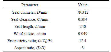
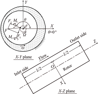
Fig. 1 Circular whirl orbit and induced fluid loads
3 Numerical method
3.1 Solution approach
In this study, the commercial CFD solver, ANSYS Fluent 14.0, is adopted to solve the 3-D Navier�CStokes equations. The second-order upwind scheme with numerical under-relaxation is applied to the convection term in the equations. The diffusion flux is discretised using the central-differencing scheme. The well-known SIMPLE strategy is used to deal with velocity�Cpressure coupling.
Pressure loss and swirl velocity at seal entrance have important effects on the dynamic characteristics of annular seals [3]. Thus, modeling the annular seal with a section of the upstream region [15] is a wise practice to consider the effects of inlet loss and inlet swirl. The profile of the 3-D numerical model with a section of the upstream region is shown in Fig. 2, along with the main boundaries, zones and meshing scheme.
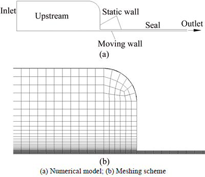
Fig. 2 Profile of long annular seal including upstream region:
The turbulence model used in the work is the Realizable k-�� model with enhanced wall treatment [20], and the inlet boundary condition has a total pressure of 907 kPa. The inlet condition of total pressure is accomplished by applying the Bernoulli equation shown as [20]
 (2)
(2)
where Po is total pressure; Ps is static pressure; �� is density and v is fluid velocity. This condition allows static pressure and velocity to reasonably develop at the inlet boundary. The outlet boundary condition is static pressure 0 Pa, and the rotating speed of the moving wall is 1080 r/min.
The structured grids in Fig. 2 are generated using the CFD pre-processor, Gambit. Grid partitioning in the seal clearance is 10��240��244, namely 10 layers of grids are generated along the seal clearance, 240 layers in the axial direction and 244 layers in the circumferential direction. For this grid model, the wall Y+ is located in the range of 20-40, and the enhanced wall function is suitable for the range [20].
3.2 Two quasi-steady methods
A displacement e (0.049 mm) along the +X axial direction is imposed on the rotor to generate the eccentric flow field (eccentricity ratio e/Cr 12.4%), and the rotor is assumed to perform a circular whirl motion with constant speed �� in the annular seal, as shown in Fig. 3(a). Dynamic fluid forces on the rotor can be obtained by solving the whirling flow field, and then are used to compute the rotordynamic coefficients of the annular seal.
The whirling flow field in Fig. 3(a) can be directly solved under a static reference frame (SRF), but it is a transient problem that needs a dynamic mesh. To avoid the complexities of transient solutions, the quasi-steady method (Fig. 3(b)) was proposed and widely used [10, 12, 13, 15]. The transient flow problem in Fig. 3(a) can be converted into a steady one in Fig. 3(b) by solving the eccentric flow field under the MRF attached to the whirling rotor. This method is termed the traditional quasi-steady method in this paper. The only shortcoming of this method is that it assumes the whole flow field except the seal��s static wall performing the whirl motion along with the rotor, a result that is not consistent with actual flow conditions. The traditional quasi-steady method (Fig. 3(b)) is improved by splitting the annular flow field into two regions along the middle surface of the seal, i.e. inner fluid zone and the outer one in Fig. 3(c). Only the inner fluid zone near the rotor is treated as a whirling zone, and it is solved under the MRF. The reliabilities and differences of the traditional and improved quasi-steady methods in Fig. 3 are identified by comparison with experimental results in Section 5.2.
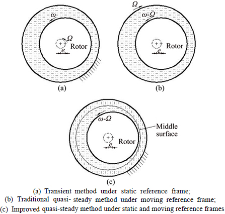
Fig. 3 Schematic plots of three CFD methods:
Quasi-steady CFD simulations based on the two methods can serve to obtain the fluid-induced forces, Fx and Fy, by integrating the pressure on the rotor surface. As depicted in Fig. 1, the radial and tangential forces (Fr, Ft) on the eccentric rotor in Fig. 3 can be expressed by
 (3)
(3)
where Fx and Fy are fluid forces in X and Y directions.
3.3 Transient method
The transient CFD method in Fig. 3(a) directly solves the transient flow under SRF without any quasi-steady simplification. To perform the transient CFD computations, the dynamic mesh problem should be settled first. In this work, the dynamic mesh is achieved by a user-defined subroutine, which linked with the CFD solver. This can strictly control the motion of every grid node in the seal model. The nodes on the rotor surface perform the circular whirl motion described by Eq. (1), and the nodes on the outer wall (static wall) are stationary. The motions of other nodes between rotor surface and static wall are determined using the interpolation method based on the distances of the nodes from the two walls. Good mesh quality can be guaranteed by this strict control.
On transient CFD simulations, the time spent by the rotor at each 1�� whirl is chosen as the time step. First- order implicit formulation is used for the discretisation of the transient term.
During the transient computations, the fluid forces (Fx, Fy) at each time step can be extracted by integrating the pressure on the rotor. As shown in Fig. 1, the radial and tangential components of fluid forces can be expressed by
 (4)
(4)
Substituting (Fx, Fy) into Eq. (4) can obtain the radial and tangential forces (Fr, Ft) induced by the circular whirl motion of the rotor.
3.4 Estimations of rotordynamic coefficients
For the circular whirl motion with eccentricity ratio 12.4% (e/Cr), the linear characteristics of the seal can be captured and fluid-induced forces are expressed in the linearized rotordynamic form [12] shown as
 (5)
(5)
where K and k are direct and cross stiffness coefficients, respectively; C and c are direct and cross damping coefficients, respectively; and M is direct mass coefficient.
Substituting Eqs. (1) and (5) into Eq. (4), the radial and tangential fluid forces can be expressed as a function of whirling speed W as follows:
 (6)
(6)
By using one of the two quasi-steady methods and the transient method, the fluid forces (Fr, Ft) under different whirling speeds can be computed. Then, based on Eq. (6), the five rotordynamic coefficients of the annular seal can be obtained via curve fittings.
4 Identification of grid densities
Identification of the present grid model is performed by comparing with other grid models as follows:
Grid 1: The present grid model (10��240��244).
Grid 2: Radial grid number is decreased to six layers to be suitable for the standard wall function (6��240��244).
Grid 3: Radial grid number is increased to 14 layers and enhanced wall treatment is also used (14��240��244).
Grid 4: Axial and circumferential grid numbers are increased to reduce the grid aspect ratio (less than 12) and to improve grid quality (10��720��732).
The adopted numerical method is the improved quasi-steady method. The whirling flow field is solved based on the four grid models. The radial and tangential fluid forces induced by the whirl motions with different speeds are computed and shown in Fig. 4 for comparisons.
As shown in Fig. 4, although different wall functions are used, the fluid forces do not exhibit significant variations when the grid densities are changed based on the present grid model (10��240��244). The curves of Fr and Ft from the four grid models are very similar to each other, and then the estimated dynamic coefficients from these curves wouldn��t differ too much. Therefore, the present grid model is reliable for the following studies.
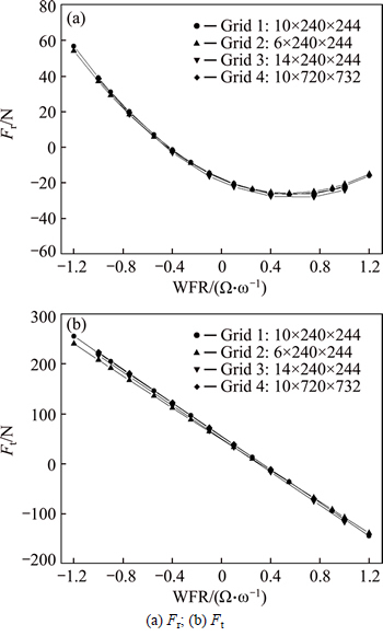
Fig. 4 Fluid forces computed by four grid models (improved quasi-steady method):
5 Results and discussions
5.1 Fluid forces and dynamic coefficients under uniform incoming flow
According to the numerical model in Fig. 2, the flow field of annular seal disturbed by the circular whirl motions of the rotor is solved using the three CFD methods, namely, the traditional quasi-steady, improved quasi-steady methods and the transient method, introduced in sections 3.2 and 3.3, respectively. The fluid forces are computed and used to evaluate the five rotordynamic coefficients.
For transient computations, the components of fluid force in the rectangular coordinate system, Fx and Fy, are varying with time. Figure 5 displays the time histories of fluid forces obtained by the transient CFD simulation. The speed of whirl motion is -1080 r/min, i.e., the ratio of rotor whirl to rotor rotation (WFR) is -1. The Fx and Fy are directly extracted from Fluent 14.0 solver by monitoring the pressure force on the rotor at each time step. The radial and tangential components of fluid force in Fig. 1, Fr and Ft, are obtained by employing the coordinate transformation in Eq. (4). As seen in Fig. 5, the convergence of solution is so fast that the Fr and Ft have been keeping constant since 0.01 s (less than 1/5 whirl period).
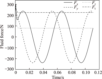
Fig. 5 Fluid forces induced by -1080 r/min whirl motion under uniform incoming flow
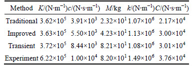
Similar transient simulations can obtain the Fr and Ft under other whirling speeds. They are presented in Fig. 6 along with fluid forces obtained from the two quasi-steady methods and the experiment [19]. By fitting the curves of Fr and Ft in Fig. 6 based on Eq. (6), the rotordynamic coefficients from the experiments, traditional quasi-steady method, improved quasi-steady method and transient method are obtained respectively. And these coefficients are presented in Table 2.
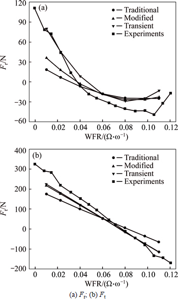
Fig. 6 Fluid forces from quasi-steady and transient methods under uniform incoming flow:
Table 2 Dynamic coefficients from different CFD methods
5.2 Experimental validation for three CFD methods
As shown in Table 2, the five rotordynamic coefficients computed by the two quasi-steady methods are all smaller than those in experiments. The cross damping c, direct mass M and direct damping C obtained by the two quasi-steady methods are obviously different from each other. The three coefficients from the improved quasi-steady method are larger than the coefficients from the traditional quasi-steady method, and are much closer to experimental results. These trends are consistent with the variations of fluid forces in Fig. 6. Owing to the better prediction for c, M and C, the radial forces from the improved quasi-steady method are more curved upwards to approach the measured values, and the tangential forces from the improved method is steeper to approach the measured results. This reveals that the improved quasi-steady method in Fig. 3(c) is more reliable than the traditional one. This is because the improved method takes only the inner fluid zone near the rotor as the whirling zone, and only this fluid zone is solved under MRF, which is a little closer to actual flow conditions. From this point of view, the transient method may be more advanced, because it can directly solve the transient whirling flow field under SRF without any quasi-steady simplifications.
As shown in Table 2, when the transient method is used, the estimation of direct stiffness K increases slightly, but the predictions for cross damping c and direct mass M are largely improved. The calculated value of M almost equals to the experimental value. Overall, the improved quasi-steady method improves the predictions for c, M and C with respect to the traditional quasi-steady method. Then, the transient method provides further improvements in the predictions for c and M. The major advantage of the transient method lies in its accurate prediction for the mass term M; owing to the quasi-steady simplification, the traditional quasi-steady method underestimates as about 3/4 as original M and the improved quasi-steady method as nearly 1/2. For the long liquid seal with large aspect ratio (L/D), its mass coefficient (82 kg) is large, and the transient method will be preferable.
In Fig. 6, owing to the improvements in predicting cross damping c and direct mass M, the radial forces Fr obtained by transient method are very close to the measured values under large negative WFR. Given this little improvement in predicting direct stiffness K, the Fr obtained from the transient method are similar with those from the quasi-steady methods under the WFR range over [-0.1, 0.8], and they are all smaller than the experimental values in absolute size. The cross stiffness k and direct damping C obtained from the transient and improved quasi-steady methods are similar to each other (Table 2), corresponding to their proximities in tangential forces Ft. The computed direct damping C is slightly lower than the measured value, leading to the smaller predictions for tangential forces in absolute size.
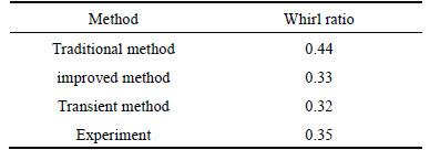
According to the rotordynamic coefficients in Table 2, the supporting-stiffness (i.e., direct stiffness coefficient K) of the long liquid seal is much smaller than the large cross stiffness coefficient k. The big direct mass coefficient M is also one major feature of long liquid seals. In terms of Eq. (6), the large cross stiffness k corresponds to the large Ft which tends to enhance the whirl motion of the rotor; the large direct mass M leads to the large Fr which tends to enlarge the rotor eccentricity. In one word, the long seals with large k and M are not very good for rotor stability. The whirl ratio is often used by rotor dynamicists to examine the stability of rotor-seal system. It is defined as
 (7)
(7)
When the WFR of rotor is in the range of 0-fw, the tangential fluid force on the rotor becomes destabilizing. The whirl ratios obtained from the experiment and three CFD methods are shown in Table 3. Both the improved quasi-steady method and the transient method have good predictions for the whirl ratio compared with the experimental value.
Table 3 Whirl ratios of annular seal
5.3 Dynamic characteristics under non-uniform incoming flow
As discussed above, the difference between the simulations and experiments in predicting fluid forces remains, which can be attributed to the under-predictions for direct stiffness K, cross damping c and direct damping C. But the reasons for under-predicting these coefficients are still unknown [10, 15]. At present, the rotordynamic coefficients of annular seal are evaluated under the assumption of uniform incoming flow. However, the effects of non-uniform incoming flow on seal dynamic coefficients may be large and need to be investigated, i.e., studying the dynamic characteristics of annular seals under non-uniform incoming flow.
According to the apparatus in Ref. [19], the full upstream region of the studied long seal is considered and simplified for modelling. The simplified numerical model with a full upstream region is shown in Fig. 7. The flow is assumed to come from one straight pipe far away from the long seal. The flow field is solved based on the numerical model in Fig. 7, and the effect of non-uniform incoming flow can be considered. The pipe inlet is set to the condition of flow rate. The flow rate is the same with those in previous simulations in order to ensure that the pressure difference between the two sides of the seal is approximately 907 kPa.
The eccentric displacement of the rotor still keeps 0.049 mm in four eccentric directions (i.e. +X, +Y, -X and -Y directions). The four eccentric flow fields without the whirl motion of the rotor are solved, and the obtained fluid forces are used to compute the direct stiffness coefficient K' and cross stiffness coefficient k' according to Eq. (6). The superscript ' is used to represent the condition of non-uniform incoming flow. The stiffness coefficients in different eccentric directions are presented in Table 4.
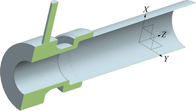
Fig. 7 Numerical model with full upstream region (sectional view)
Table 4 Stiffness coefficients (non-uniform incoming flow)
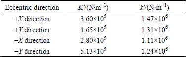
As shown in Table 4, the stiffness values under four eccentric directions are all different, especially the direct stiffness K' in the case of non-uniform incoming flow. Moreover, the transient CFD simulation is performed to study the fluid force variations with time. The fluid forces induced by -1080 r/min whirl motion are computed and shown in Fig. 8: the Fx and Fy curves vary sinusoidally with the same amplitude, and the frequency is the whirling frequency. However, unlike the fluid forces in Fig. 5 (uniform incoming flow), the peak values of Fx and Fy are no longer the same, which leads to the sinusoidal variations of Fr and Ft.
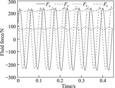
Fig. 8 Fluid forces induced by -1080 r/min whirl motion in the case of non-uniform incoming flow
As shown in Fig. 8, fluctuations of Fr and Ft begin to be cyclically steady after the fifth period, which means the solution has already converged. The variation curves of Fx and Fy in the sixth period are used to fit their expressions in Eq. (8):
 (8)
(8)
where the existence of constant terms (-0.518 N, 10.499 N) in Eq. (8) inevitably causes the fluctuant variations of Fr and Ft in Fig. 8. Where do the constant terms come from? The concentric flow field without eccentricity is solved based on the numerical model in Fig. 7. Then, the fluid forces in the concentric annular seal (labelled as Fx0, Fy0) are obtained. Owing to the non-uniformity of incoming flow, the forces are nonzero, Fx0=0.291 N and Fy0=9.284 N respectively. They are similar with the constant terms in Eq. (8). This means the constant terms actually perform as the Fx0 and Fy0 do.
Similarly, the fluid forces in the annular seal with non-uniform incoming flow can be described in a linearized rotordynamic form. The formulas are presented and shown in Eq. (9):

 (9)
(9)
With respect to Eq. (5), Eq. (9) introduces the Fx0 and Fy0 to consider the effects of non-uniform incoming flow. The rotordynamic coefficients in Eq. (9) are all obtained under the condition of uniform incoming flow, and they are different from the coefficients in Table 4. For the annular seal with uniform incoming flow, Fx0 and Fy0 become zero, and Eq. (9) can turn into Eq. (5). Therefore, Eq. (9) presented in the work is a general expression.
Substituting Eq. (1) into (9), the expressions of Fx and Fy can be obtained from Eq. (10):
 (10)
(10)
where it is consistent with Eq. (8). According to Eq. (6), the four coefficients of trigonometric functions in Eq. (8) or (10) represent the Fr and Ft under the condition of uniform incoming flow in Figs. 5 and 6.
In Table 4, the changes of stiffness values in different eccentric directions can be explained by Eq. (9). Taking the rotor eccentricity in +X direction for example, x=e and y=0 are substituted into Eq. (9) and the fluid forces can be expressed as follows:
 (11)
(11)
For the eccentricity in +X direction, Eq. (3) is employed as:
 (12)
(12)
According to Eq. (6), the stiffness coefficients in +X eccentric direction can be expressed as follows:
 (13)
(13)
In Eq. (13), when the incoming flow is non-uniform, the term Fy0/e is appended to k and leads to the increase of cross stiffness k' in +X eccentric direction, as shown in Table 4 (Fy0 is approximately 9.248 N). Similarly, the changes of stiffness coefficients in other eccentric directions can also be explained based on Eq. (9). In brief, these changes are all attributed to the existence of (Fx0, Fy0).
In fluid machinery, the non-uniform incoming flow in front of annular seals can be hardly avoidable. However, when studying the dynamic characteristics of annular seals under non-uniform incoming flow, the uniform incoming flow can still be assumed to evaluate their rotordynamic coefficients. Then, by combining the dynamic coefficients with the fluid forces under the concentric condition (Fx0, Fy0), the fluid forces generated in the annular seal with non-uniform incoming flow can be investigated by using the linearized rotordynamic formulas shown in Eq. (9). In addition, when the rotordynamic coefficients of annular seals are studied through experiments, the forces (Fx0, Fy0) induced by the non-uniform incoming flow of the test apparatus should be removed from the measured fluid forces.
6 Conclusions
1) The comparisons between experimental data indicate that the performance of the improved quasi-steady method is better than the traditional quasi-steady one, and the transient method outperforms the other two. However, the transient method is so time-consuming that it occupies much more computing resources than those of two quasi-steady methods. Compared with improved quasi-steady method, the main advantage of transient method is its accurate prediction for the mass coefficients of annular seals. Thus, for the annular seals with small mass coefficients (e.g. short seals or gas seals), the improved quasi-steady method can be more conveniently used to study seals dynamic characteristics.
2) For the long liquid seal, its cross stiffness coefficient k and direct mass coefficient M are relatively large. The larger k and M mean that the radial and tangential fluid forces on the rotor have more chances to be the destabilizing forces, which is not good for rotor stability. The direct mass coefficient M is accurately predicted by the transient CFD method. However, the two quasi-steady methods underestimate it by nearly 1/2 and 3/4 respectively, due to their quasi-steady simplifications. Thus, for the long annular seals with large inertia terms, the transient method is preferable for its distinct advantage in predicting M, which is important for stability analysis of rotor system.
3) In fluid machinery, the fluid forces under the concentric condition of annular seals, Fx0 and Fy0, are nonzero because of the non-uniform intake flow before annular seals. The existence of Fx0 and Fy0 leads to the variations of stiffness coefficients with eccentric directions. Based on the rotordynamic coefficients under uniform incoming flow, the dynamic characteristics of annular seals under non-uniform incoming flow can be studied by combining the effects of Fx0 and Fy0. In turn, when the rotordynamic coefficients of annular seals are predicted by numerical computations or experiments, the effects of Fx0 and Fy0 should be removed.
References
[1] ARGHIR M, FRENE J. Static and dynamic analysis of annular seals [C]// Proceedings of ASME Fluids Engineering Division Summer Meeting 2006. New York, USA: ASME, 2006: 517-526.
[2] PING Shi-liang, TAN Shan-guang, WU Da-zhuan, WANG Le-qin. Analysis on modeling rotor system with sidling bearing and ring seal by using FEM [C]// Proceedings of the 4th International Symposium on Fluid Machinery and Fluid Engineering. Berlin, Heidelberg, Germany: Springer, 2009: 366-370.
[3] CHILDS D W. Turbomachinery rotordynamics: phenomena, modeling, and analysis [M]. New York: John Wiley & Sons, 1993.
[4] HIRS G G. A bulk-flow theory for turbulence in lubricant films [J]. Journal of Tribology, 1973, 95(2): 137-145.
[5] MARQUETTE O R, CHILDS D W, SAN ANDRES L. Eccentricity effects on the rotordynamic coefficients of plain annular seals: Theory versus experiment [J]. Journal of Tribology, 1997, 119(3): 443-448.
[6] NELSON C C, NGUYEN D T. Comparison of Hirs�� equation with Moody��s equation for determining rotordynamic coefficients of annular pressure seals [J]. Journal of Tribology, 1987, 109(1): 144-148.
[7] SUN Dan, YANG Jian-gang, GUO-rui, ZHANG Wan-fu, AI Yan-ting. A trigonometric series expansion based method for the research of static and dynamic characteristics of eccentric seals [J]. Journal of Mechanical Science and Technology, 2014, 28(6): 2111-2120.
[8] GUPTA M K, CHILDS D W. Rotordynamic stability predictions for centrifugal compressors using a bulk-flow model to predict impeller shroud force and moment coefficients [J]. Journal of Engineering for Gas Turbines and Power, 2010, 132(9): 091402.
[9] TAM L T, PRZEKWAS A J, MUSZYNSKA A, HENDRICKS R C, BRAUN M J, MULLEN R L. Numerical and analytical study of fluid dynamic forces in seals and bearings [J]. Journal of Vibration, Acoustics, Stress, and Reliability in Design, 1988, 110(3): 315-325.
[10] HA T W, CHOE B S. Numerical prediction of rotordynamic coefficients for an annular-type plain-gas seal using 3D CFD analysis [J]. Journal of Mechanical Science and Technology, 2014, 28(2): 505-511.
[11] ZHANG Meng, WANG Xiao-fang, XU Sheng-li, WAN Xue-li. Analysis of the stiffness of the incompressible seal in pump [J]. Journal of Harbin Engineering University, 2014, 35(3): 347-352. (in Chinese)
[12] UNTAROIU A, HAYRAPETIAN V, UNTAROIU C D, WOOD H G, SCHIAVELLO B, MCGUIRE J. On the dynamic properties of pump liquid seals [J]. Journal of Fluids Engineering, 2013, 135(5): 051104.
[13] GAO R, KIRK G. CFD study on stepped and drum balance labyrinth seal [J]. Tribology Transactions, 2013, 56(4): 663-671.
[14] MOORE J J, RANSOM D L, VIANA F. Rotordynamic force prediction of centrifugal compressor impellers using computational fluid dynamics [J]. Journal of Engineering for Gas Turbines and Power, 2011, 133(4): 042504.
[15] MOORE J J, PALAZZOLO A B. CFD comparison to 3D laser anemometer and rotordynamic force measurements for grooved liquid annular seals [J]. Journal of Tribology, 1999, 121(2): 306-314.
[16] YAN Xin, LI Jun, FENG Zhen-ping. Investigations on the rotordynamic characteristics of a hole-pattern seal using transient CFD and periodic circular orbit model [J]. Journal of Vibration and Acoustics, 2011, 133(4): 041007.
[17] YAN Xin, HE Kun, LI Jun, FENG Zhen-ping. A generalized prediction method for rotordynamic coefficients of annular gas seals [J]. Journal of Engineering for Gas Turbines and Power, 2015, 137(9): 092506.
[18] NIELSEN K K,  K, UNDERBAKKE H. Hole-pattern and honeycomb seal rotordynamic forces: Validation of CFD-based prediction techniques [J]. Journal of Engineering for Gas Turbines and Power, 2012, 134(12): 122505.
[19] KANEMORI Y, IWATSUBO T. Experimental study of dynamic fluid forces and moments for a long annular seal [J]. Journal of Tribology, 1992, 114(4): 773-778.
[20] ANSYS FLUENT 14.0 Theory Guide [CP/DK]. USA: ANSYS Inc., 2011.
(Edited by DENG L��-xiang)
Cite this article as:
WU Da-zhuan, JIANG Xin-kuo, CHU Ning, WU Peng, WANG Le-qin. Numerical simulation on rotordynamic characteristics of annular seal under uniform and non-uniform flows [J]. Journal of Central South University, 2017, 24(8): 1889-1897.
DOI:https://dx.doi.org/https://doi.org/10.1007/s11771-017-3596-4Foundation item: Project(51276213) supported by the National Natural Science Foundation of China; Project(2013BAF01B00) supported by the National Science and Technology Support Program of China
Received date: 2015-12-23; Accepted date: 2016-05-11
Corresponding author: WU Da-zhuan, PhD, Professor; Tel: +86-13989880802; E-mail: wudazhuan@zju.edu.cn
Abstract: Currently, the flow field of annular seals disturbed by the circular whirl motion of rotors is usually solved using computational fluid dynamics (CFD) to evaluate the five rotordynamic coefficients. The simulations are based on the traditional quasi-steady method. In this work, an improved quasi-steady method along with the transient method was presented to compute the rotordynamic coefficients of a long seal. By comparisons with experimental data, the shortcomings of quasi-steady methods have been identified. Then, the effects of non-uniform incoming flow on seal dynamic coefficients were studied by transient simulations. Results indicate that the long seal has large cross stiffness k and direct mass M which are not good for rotor stability, while the transient method is more suitable for the long seal for its excellent performance in predicting M. When the incoming flow is non-uniform, the stiffness coefficients vary with the eccentric directions. Based on the rotordynamic coefficients under uniform incoming flow, the linearized fluid force formulas, which can consider the effects of non-uniform incoming flow, have been presented and can well explain the varying-stiffness phenomenon.
