
J. Cent. South Univ. (2012) 19: 2468-2476
DOI: 10.1007/s11771-012-1298-5![]()
Semi-physical simulation of AUV pipeline tracking
LI Ye(����), PANG Yong-jie(������), ZHANG Lei(����), ZHANG Hong-hao(�ź��)
State Key Laboratory of Autonomous Underwater Vehicle (Harbin Engineering University), Harbin 150001, China
? Central South University Press and Springer-Verlag Berlin Heidelberg 2012
Abstract:
Before the task of autonomous underwater vehicle (AUV) was implemented actually, its semi-physical simulation system of pipeline tracking had been designed. This semi-physical simulation system was used to test the software logic, hardware architecture, data interface and reliability of the control system. To implement this system, the whole system plan, including interface computer and the methods of pipeline tracking, was described. Compared to numerical simulation, the semi-physical simulation was used to test the real software and hardware more veritably. In the semi-physical simulation system, tracking experiments of both straight lines and polygonal lines were carried out, considering the influence of ocean current and the situation of buried pipeline. The experimental results indicate that the AUV can do pipeline tracking task, when angles of pipeline are 15��, 30��, 45�� and 60��. In the ocean current of 2 knots, AUV could track buried pipeline.
Key words:
1 Introduction
At present, autonomous underwater vehicle (AUV) has become an effective tool in many realms, such as exploration of marine biology [1], sampling of minerals [2], wrecking rescue [3], ocean engineering [4], and inspection to dam [5]. Due to the inconvenience of underwater observation and underwater communication, once the fault appeared, AUV would possibly be lost. So it was necessary to ensure the stability and reliability. AUV was made up of communication system, navigation system, sonar system, energy system, propulsion system and intelligent control system [6], which made the performance evaluation of AUV become more difficult. For the complexity of AUV and the limitation of sensors, it was dangerous to work actually before the accurate confirmation had been obtained in reliability, stability and autonomous ability. Therefore, the verification and evaluation of the overall performance has become more and more important [7].
Based on the technology of modern computer network, semi-physical simulation could effectively reduce the calculation time. The real units could be joined into the simulation system as far as possible. The actual hardware system, software logic and data interface could be tested in the simulation. The distinctive characteristic of semi-physical simulation was ��hardware in the loop�� [8], which reduced the error of mathematic modeling. The semi-physical simulation of AUV has become a crucial step in the process.
Corresponding researches have been done. American Advanced Research Projects Agency developed an AUV simulator. It was made up of a large computer, sonar model, and internal units of AUV. The simulator provided the hardware interface between large computer and vehicle. It was mainly used to do the system debugging before the sea trial. It could also be used to test each single unit of the vehicle. In the semi-physical simulation, the block diagram demonstrated the position of AUV. All software parts of the simulator, including graphics interface, were processed in a single thread. So the software architecture could not be extended unrestrainedly.
In University of Tokyo, researchers have developed a simulation system of AUV, to test its software and hardware system [9]. In the development of ��Twin-Burger AUV��, the simulator was applied successfully.
In Naval Postgraduate School of USA, the underwater simulation provided 3D real-time virtual scene [10]. A hydrodynamic model of AUV in six degrees of freedom was established. And the sonar simulation was provided. The application of the IEEE Distributed Interactive Simulation (DIS) protocol enabled it to interact with other virtual worlds through the internet. The underwater virtual world was developed by C++ language, OpenGL graphic library and Open Inventor graphics software package.
In National Key Laboratory of AUV in Harbin Engineering University, China, the simulation research was conducted and used to design ��ZS-IV AUV��. The research indicated that the simulator played a crucial role, in the improvement of software reliability and hardware architecture. The simulation included 3D scene and omni-directional observation of the moving AUV. It also provided the sonar simulation. This system was developed with the C language and Vega software package [11-12].
Previous AUV simulations have made effective attempt in reliability of control system. However, little research has been done on the dynamic simulation of ocean current, optical simulation, and underwater object detection. Especially, little has been done to the simulation of underwater operation. So, in this work, to carry out the semi-physical simulation, research with background of pipeline tracking is conducted.
2 Simulation system
The simulation system is shown in Figs. 1 and 2. Figure 1 shows the hardware architecture of simulation system. Figure 2 shows real control cabin of AUV.
Graphic workstation, ��OCATN II��, was taken as the simulation center. Combined with five host computers, the simulation system was built with the network communication and serial communication.
The IRIX6.5 operation system was installed in ��OCATN II��. It was mainly used to realize scene simulation, hydrodynamic calculation, and simulation of sensors.
The interface computer was the X86 PC, with 8-serial-channel PCI card and the D/A and A/D converters. The simulation results of sensors were sent from ��OCATN II�� to interface computer, by TCP/IP protocol. These results were transformed into the formation of actual sensors. It was used to simulate the signals of doppler velocity log (DVL), optic-fiber compass, depthometer, altimeter, and propellers.
In Fig. 1, the part in the dashed-line frame was the real control cabin, which was directly fixed in the hull of AUV. In the real cabin, many units were assembled, including the units of motion control, navigation, path planning, acoustic processing, optical processing and communication. With PC/104-bus, multi-board-stack and embedded structure, these computers contained integrated Pentium processor, power module, and interface cards, such as serial port card, D/A card and A/D card, according to the requirement of different missions.
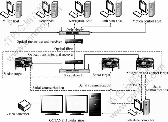
Fig. 1 Hardware architecture of simulation system
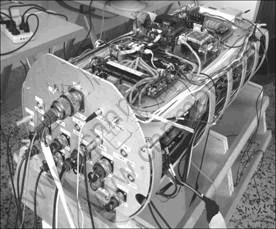
Fig. 2 Real control cabin of AUV
The host computers were development tools of the optical vision, acoustic vision, navigation, path planning, and motion control. All of these computers were general PC, with the Windows XP operation system. By the integrated development environment of ��Tornado��, the BSP of VxWorks and the program of corresponding functional module were developed. Through the way of switchboard��optical transmitter and receiver��optical fiber��optical transmitter and receiver�� switchboard, the network was built up between the host computers and the embedded computers in real control cabin.
The functions of those computers were defined as follows:
1) ��OCATN II�� workstation
It realized the hydrodynamic calculation, motion simulation, vision simulation and sonar-detection simulation of the vehicle. The simulator obtained the field of vision by virtual camera, and sent the video signal to the video converter, which converted the signal from VGA to PAL. Then PAL signal was sent to the optical vision target computer.
2) Interface computer
It received output data of sensor simulation from the ��OCATN II�� workstation, transformed it into the format same as the actual sensors, and then sent the signal to the target computers.
3) Optical vision host computer
It developed the embedded program, and downloaded it into the optical vision target computer.
4) Optical vision target computer (PC/104)
It gathered the video signal, processed the image, identified pipeline, and sent the results to the control system.
5) Acoustic vision host computer
It developed the embedded program, and downloaded it into the acoustic vision target computer.
6) Acoustic vision target computer (PC/104)
It received output signal of sonar simulation from interface computer, processed acoustic image, identified pipeline, and sent the results to the control system.
7) Navigation/motion control host computer
It developed the embedded program for the control target computer, monitored the control target computer, took over the right of motion control when it was necessary, and realized the manual control.
8) Navigation/motion control target computer (PC/104)
It received motion information from interface computer, calculated control output, sent control commands, and completed the motion control.
All computers were joined to the local area network, with the TCP/IP communication.
3 Interface computer
The first function of interface computer was to receive control commands from navigation/motion control target computer (PC/104), and retransmitted them to the ��OCTAN II�� workstation. Secondly, it received the information of current position, speed, sonar information from the ��OCTAN II�� workstation, and transformed them into corresponding data format of actual sensors. Then the information was provided to the target computers (PC/104). It was the bridge between the control cabin and ��OCTAN II�� workstation. For the target computers (PC/104), the data signal obtained from semi-physical simulation was completely the same as the data from real sensors. In the semi-physical simulation, the same program of actual operation could be adopted. It strengthened the reliability of system test.
The movement of AUV depended on the ducted propellers and rudders. Control commands of the ducted propellers were voltage signals. Voltage was proportional to rotary speed, and was in a linear relationship with the thrust force. The interface computer gathered the voltage commands sent by navigation/motion control target computer (PC/104), carried out the A/D conversion, and sent the command to the ��OCTAN II�� workstation by socket. The rudder was controlled by stepping motor. Its control signal was the square-wave pulse with different frequencies. While the interface computer received pulse signal, it calculated the angle for stepping motor. Through the conversion of transmission ratio, the rotation angle of rudder was obtained. The value was also sent to the ��OCTAN II�� workstation by socket.
The real-time quality of simulation wasn��t emphasized, due to the fact that AUV sailed at no more than 1 m/s, in the underwater operation. So the software of interface computer was based on the MS Windows. Figure 3 shows the software interface. The software was divided into four regions: 1) serial sensor, 2) network communication, 3) DA/AD conversion, and 4) software state.
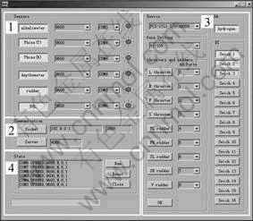
Fig. 3 Software of interface computer
The communication settings of sensors were completed in the serial sensor region 1. As shown in Fig. 3, the different serial parameters could be changed according to the sensor. The corresponding sensor was clicked after the parameters were set. Then this sensor could be joined into the simulation. The interface software communicated with ��OCTAN II�� workstation. The software received the information of position and speed calculated by hydrodynamic program, and sent the control commands to hydrodynamic program. It ensured the data to be accurately transmitted by the TCP/IP socket communication. The DA/AD conversion region was mainly used to gather analog signal of propellers and rudders, transformed the analog signal to the digital signal, and then transmitted to ��OCTAN II�� workstation.
4 Maneuverability simulation near seabed
Hydrodynamic model of AUV was founded by maneuverability equation in six degrees of freedom [13], considering the simulation of propellers and rudders, as well as environment influence. The hydrodynamic coefficients were obtained by the maneuverability experiment by the plane motion mechanism (PMM) or its numerical calculation [14]. The simulation of propellers and rudders was done according to the result of open water test [15]. The environmental influence was based on the ocean current distribution in actual region [16]. The environmental influence was transformed to force or moment in each degree of freedom. Then the acceleration was calculated in each degree of freedom, and integrated to get the motion of AUV.
The calculation of acceleration could be represented as
![]() (1)
(1)
where, ![]() is the acceleration in six degrees of freedom, Fvis is the non-inertial hydrodynamic force, Ft is the control force, and E is the coefficient matrix:
is the acceleration in six degrees of freedom, Fvis is the non-inertial hydrodynamic force, Ft is the control force, and E is the coefficient matrix:
 (2)
(2)
where m is the mass of AUV, xG and zG are coordinates of gravity center; ![]() ,
, ![]() ,
, ![]() ,
, ![]() ,
, ![]() ,
, ![]() ,
, ![]() ,
, ![]() ,
, ![]() ,
, ![]() ,
, ![]() ,
, ![]() ,
, ![]() and
and ![]() are hydrodynamic parameters. When AUV sailed in the restricted water, such as approaching to water surface, near seabed, or in the narrow channel, its hydrodynamic characteristic changed obviously. In the practical work of pipeline tracking and detection, AUV has to sail close to the seabed. The seabed influence would change the maneuverability of AUV certainly. Taking the effect of the seabed on maneuverability into account, the forecast of motion has actual significance to the operation [17]. The experimental results indicated that various hydrodynamic coefficients increased along with the diminution of H/D, in which H is the distance between AUV and seabed, and D is vertical diameter of AUV. The seabed influence made the hydrodynamic coefficients increase. Therefore, it was necessary to adjust hydrodynamic coefficients, according the value of H/D, and simulate hydrodynamic forces near seabed.
are hydrodynamic parameters. When AUV sailed in the restricted water, such as approaching to water surface, near seabed, or in the narrow channel, its hydrodynamic characteristic changed obviously. In the practical work of pipeline tracking and detection, AUV has to sail close to the seabed. The seabed influence would change the maneuverability of AUV certainly. Taking the effect of the seabed on maneuverability into account, the forecast of motion has actual significance to the operation [17]. The experimental results indicated that various hydrodynamic coefficients increased along with the diminution of H/D, in which H is the distance between AUV and seabed, and D is vertical diameter of AUV. The seabed influence made the hydrodynamic coefficients increase. Therefore, it was necessary to adjust hydrodynamic coefficients, according the value of H/D, and simulate hydrodynamic forces near seabed.
5 Pipeline tracking simulation system based on underwater camera
Generally, the inspection task of underwater pipeline was arduous and interminable. Especially, in bad visibility or in ocean current environment, the task became more difficult. When the pipeline inspection was done automatically by AUV, it needed to overcome the difficulty of the weak illumination and massive suspended substance. To simulate the underwater environment, all the models of the system, such as underwater environment model, petroleum pipeline model, ocean current model and AUV dynamics model, were all established in ��OCTAN II�� workstation.
The optical vision simulation was implemented by the Vega software package. In the vision simulation software, the camera window was defined, and the viewpoint and view direction were consistent with camera. Through adjusting horizontal and vertical fields of view, the actual angle of view was simulated. Thus, the scene in the simulated camera window was equal to that in the underwater camera. The digital images in the simulated camera window were transformed into PAL signal by video converter, and then were sent out to the optical vision target computer (PC/104).
Simulation of the underwater camera-assistant light was carried out by defining light source in Vega. By changing the definition of light source brightness in Vega, the brightness adjustment was simulated. Through setting the corresponding parameters, it realized the simulation of light brightness in the software. The commands of both the light switch and the brightness adjustment were issued by the optical vision target computer (PC/104).
The underwater visibility directly affected the imaging of camera. Vega provided a class named ��Fog��, which could be used to simulate the atomizing effect. This class was used to simulate the underwater visibility. Within the simulation, the adjacent objects were clear, and the distant objects were fuzzy in the scene. Through setting the parameters of ��Fog��, the simulation of visibility, color and other characters could be realized. The simulation of the underwater visibility is shown in Fig. 4.
The tracking system took the underwater image as the survey foundation. Through the image preprocessing, pipeline type judgment, position calculation and coordinate conversion, the system finally got the navigation information (the coordinate of mass center, principal axis of inertia, nearest point, and farthest point). Figure 5 shows the sketch map of pipeline tracking.
The optical vision target computer (PC/104) sent the processing results to the navigation/motion control target computer (PC/104). AUV did the path planning according to the pipeline information and the current position was received from interface computer. It carried out the control calculation, thrust assignment, and transmitted the output voltages to the hydrodynamic module of ��OCTAN II�� workstation. After the information was converted to digital data through the interface computer, hydrodynamic module calculated motion state of AUV, and transmitted it to the navigation/motion control target computer (PC/104). Figure 6 shows the process of the semi-physical simulation experiment.
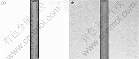
Fig. 4 Simulation of underwater atomizing effect: (a) Clear scene of underwater pipeline; (b) Fussy scene of underwater pipeline
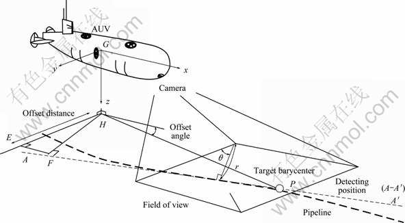
Fig. 5 Sketch map of pipeline tracking by underwater vehicle
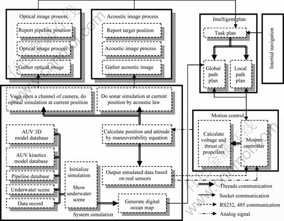
Fig. 6 Process of semi-physical simulation experiments
6 Process and results of pipeline tracking simulation experiments
A series of semi-physical simulation experiments of pipeline tracking have been carried out. The experiment scene is shown in Fig. 7. Underwater camera was installed at the head of AUV, downward at 45?. The altimeter was at vertical downward direction. With the ��Fog�� effect, underwater visibility was approximate to 6 m. In the simulation experiment, the maximum velocity of AUV was limited to 1 m/s. The optical vision target computer (PC/104) reported the pipeline position and guided AUV to move along the pipeline. AUV kept the height automatically, set the pipeline position as the expected position, and made the expected heading parallel to the pipeline.
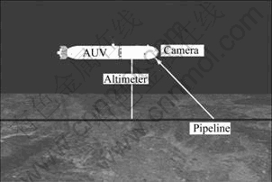
Fig. 7 Sketch map of underwater pipeline tracking
In the simulation environment, the pipeline was constructed with the diameter of 0.5 m and length of 100 m. The viewpoint was established at the place where camera was installed, and sent the video signal out. Firstly, AUV was assigned to track the straight pipeline. The image of the straight pipeline from Vega channel is shown in Fig. 8. Figure 9 shows the result of image process. The experiment process and result are shown in Figs. 10 and 11. To simulate actual underwater environment, tracking simulation reduced the visibility gradually. When the visibility was decreased to 3 m, the inspection system still had the tracking capacity.
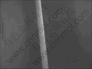
Fig. 8 Image of straight pipeline from Vega channel
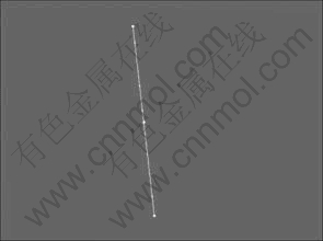
Fig. 9 Result of image processing

Fig. 10 Tracking scene of straight pipeline
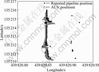
Fig. 11 Trace of straight pipeline tracking
To test persistent tracking capacity of polygonal pipeline, a test on tracking pipeline with gradually increasing angle was carried out. The angles were 15��, 30��, 45�� and 60��, respectively. The images of the pipeline from Vega channel are shown in Figs. 12 and 13. The experimental results are shown in Figs. 14 and 15.
To be consistent with the real underwater condition, the middle of the pipeline was buried to test the continual tracking capacity. Figure 16 shows the tracking result of the partly-buried pipeline. The system could overcome the tracking loss in part and had robustness to the pipeline tracking.
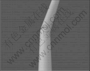
Fig. 12 Image of polygonal pipeline with Vega channel
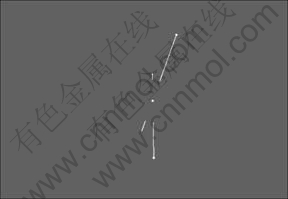
Fig. 13 Result of image processing
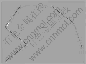
Fig. 14 Tracking scene of polygonal pipeline
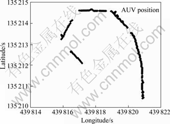
Fig. 15 Trace of polygonal pipeline tracking
To test the tracking capacity in the ocean current condition, the ocean current impulsive force was joined into the hydrodynamic simulation. The amplitude of current was 2 knots. The direction and absolute value changed with the simulation time linearly. The experimental results are shown in Figs. 17 and 18.
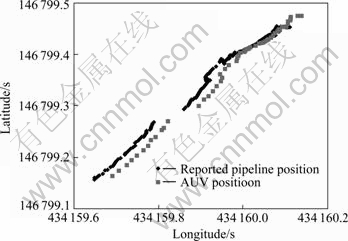
Fig. 16 Pipeline tracking in partly-buried condition
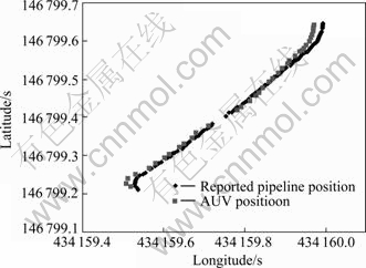
Fig. 17 Pipeline tracking in none current condition
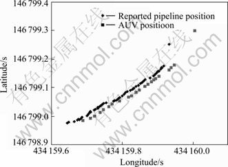
Fig. 18 Pipeline tracking in current condition
7 Conclusions
1) The semi-physical simulation system of the submarine petroleum pipeline tracking of AUV, including semi-physical simulation of the sensors and propellers, can be used to test the reliability of the control system.
2) Via the insertion of the interface computer and real control carbine, the logical structure, hardware architecture and data interface of the automatic pipeline tracking system are confirmed.
3) The experimental results indicate that the semi-physical simulation is effective, in the integration testing of navigation, operation and survey of AUV.
References
[1] STEPHEN W, TODD A, SEA K, JOSEPH C. The development of an autonomous underwater powered glider for deep-sea biological, chemical and physical oceanography [C]// Proceedings of IEEE Oceans 2007- Europe Conf. Vancouver, Canada, 2007: 1-6.
[2] MONTANARI M, EDWARDS J R, SCHMIDT H. Autonomous underwater vehicle-based concurrent detection and classification of buried targets using higher order spectral analysis [J]. IEEE Journal of Oceanic Engineering, 2006, 31(1): 188-199.
[3] HIROTOMO A, KENKICHI T, KATSUYA M. Model experiment of a launcher of a deep-sea monitoring robot system [C]// Proceedings of IEEE Oceans 2003 Conf. San Diego, USA, 2003: 671-676.
[4] ACOSTA G G, IBANEZ O A, CALVOCURTI H J, ROZENFELD. A flow-cost autonomous underwater vehicle for pipeline and cable inspections [C]// Symposium on Underwater Technology and Workshop on Scientific Use of Submarine Cables and Related Technologies. Tokyo, Japan, 2007: 331-336.
[5] NARCIS P, MARC C, PERE R, EMILI H. Mission control system for dam inspection with an AUV [C]// Proceedings of the 2006 IEEE/RSJ International Conference on Intelligent Robots and Systems. Beijing, China, 2006: 2551-2556.
[6] ROB M, HANS T H, DON W, FRANK P. Performance of an AUV navigation system at arctic latitudes [J]. IEEE Journal of Oceanic Engineering, 2005, 30(2): 443-454.
[7] ROBERT E, EIKE K. Design and simulation tools for multivariable control of unmanned underwater vehicles [C]// Proceedings of 2006 IEEE International Conference on Multisensor Fusion and Integration for Intelligent Systems. Heidelberg, Germany, 2006: 145-150.
[8] SONG F J, ANDRES F, EDGAR A. High fidelity hardware-in-the-loop simulation development for autonomous underwater vehicle [C]// Proceedings of IEEE Oceans 2007 Conf. Honolulu, HI, USA, 2007: 444-449.
[9] YOJI K, KOJI A, TAMAKI U. AUV test using real/virtual synthetic world [C]// Proceedings of IEEE Conf on Autonomous Underwater Vehicle Technology. Monterey, California, USA, 1996: 365-372.
[10] LEE C S. Collaborative environment for autonomous underwater vehicles (AUV) mission planning and 3d visualization [D]. Department of Electron Engineering, Naval Postgraduate School, California, USA, 2004.
[11] ZHAO J M, QIN Z B, PANG Y J, WAN L. Design of an integrated simulation system for AUV [J]. Computer Simulation, 2005, 22(10): 172-175. (in Chinese)
[12] WANG F, LI Y, WAN L, XU Y R. Modeling and motion control strategy for autonomous underwater vehicles [C]// Proceedings of IEEE International Conference on Mechatronics and Automation. Changchun, China, 2009: 4851-4856.
[13] LI Y, LIU J C, XU Y R, PANG Y J. Dynamics model in underwater vehicle motion control [J]. Robot, 2005, 27(2): 128-131. (in Chinese)
[14] ETTORE A D, JOAO L D, ANTONIO M P, ELGAR D S. Investigation of normal force and moment coefficients for an AUV at nonlinear angle of attack and sideslip range [J]. IEEE Journal of Oceanic Engineering, 2008, 33(4): 538-549.
[15] LI Y. Research on motion control technology for mini underwater vehicle [D]. Harbin Engineering University, 2007. (in Chinese)
[16] KANGSOO K, TAMAKI U. Optimal and quasi-optimal navigations of an AUV in current disturbances [C]// Proceedings of IEEE/RSJ International Conference on Intelligent Robots and Systems. Acropolis Convention Center, Nice, France, 2008: 3661-3667.
[17] ZHANG N, SHEN H C, YAO H Z. Numerical simulation of flow around submarine operating close to the bottom or near surface [J]. Journal of Ship Mechanics, 2007, 11(4): 498-507. (in Chinese)
(Edited by YANG Bing)
Foundation item: Projects(50909025, 51179035) supported by the National Natural Science Foundation of China; Project(HEUCFZ1003) supported by the Fundamental Research Funds for Central Universities of China
Received date: 2011-08-09; Accepted date: 2011-11-15
Corresponding author: LI Ye, Associate Professor, PhD; Tel: +86-451-82568056-1005; E-mail: liye@hrbeu.edu.cn
Abstract: Before the task of autonomous underwater vehicle (AUV) was implemented actually, its semi-physical simulation system of pipeline tracking had been designed. This semi-physical simulation system was used to test the software logic, hardware architecture, data interface and reliability of the control system. To implement this system, the whole system plan, including interface computer and the methods of pipeline tracking, was described. Compared to numerical simulation, the semi-physical simulation was used to test the real software and hardware more veritably. In the semi-physical simulation system, tracking experiments of both straight lines and polygonal lines were carried out, considering the influence of ocean current and the situation of buried pipeline. The experimental results indicate that the AUV can do pipeline tracking task, when angles of pipeline are 15��, 30��, 45�� and 60��. In the ocean current of 2 knots, AUV could track buried pipeline.
