
J. Cent. South Univ. Technol. (2007)02-0260-06
DOI: 10.1007/s11771-007-0052-x ![]()
Networked control and supervision system based on LonWorks fieldbus and Intranet/Internet
WU Min(�� ��)1, ZHAO Hong(�� ��)1, LIU Guo-ping(����ƽ)1, 2, SHE Jin-hua(�ܽ���)3
(1. School of Information Science and Engineering, Central South University, Changsha 410083, China;
2. School of Electronics, University of Glamorgan, Pontypridd CF37 1DL, UK;
3. School of Bionics, Tokyo University of Technology, Tokyo 192-0982, Japan)
Abstract:
A networked control and supervision system (NCSS) based on LonWorks fieldbus and Intranet/Internet was designed, which was composed of the universal intelligent control nodes (ICNs), the visual control and supervision configuration platforms (VCCP and VSCP) and an Intranet/Internet-based remote supervision platform (RSP). The ICNs were connected to field devices, such as sensors, actuators and controllers. The VCCP and VSCP were implemented by means of a graphical programming environment and network management so as to simplify the tasks of programming and maintaining the ICNs. The RSP was employed to perform the remote supervision function, which was based on a three-layer browser/server(B/S) structure mode. The validity of the NCSS was demonstrated by laboratory experiments.
Key words:
fieldbus; LonWorks; networked control; visual control configuration; Web database ��
1 Introduction
Accompanying the widespread use of computer networks and modern control technologies, fieldbus and Intranet/Internet technologies have come to be used in a wide range of fields, and networked control has attracted many researchers�� attention.
The fieldbus is an all-digital, serial two-way communication network that connects sensors, actuators, and controllers to form digital highways at a low level of process control. Fieldbus has become more and more important in control systems, since it offers significant advantages, such as openness, interchangeability, interoperability, quick and easy maintenance, low cost[1-5].
LonWorks system is a proprietary fieldbus system developed by the Echelon Corporation[6]. LonWorks system provides a wide range of products, and is used in a large number of processes in various fields, such as buildings, home automation, transportation and factories[7�C12]. However, the LonWorks system is complex and requires that control engineers have a thorough understanding of Neuron C language, and very familiar with internal hardware architecture[13]. This is a large obstacle to the design and configuration of network control system. Furthermore, it is not easy to use and maintain, and that results in increased costs.
In this paper a universal networked control and supervision system (NCSS) for LonWorks is presented, which covers a universal intelligent control node (ICN), the visual control and visual supervision configuration platforms (VCCP and VSCP). With the help of NCSS the engineers can avoid many pitfalls encountered in implementing LonWorks. Besides, the development of a remote supervision platform (RSP) based on Web technologies is described, and the integration of Web and LonWorks fieldbus technologies provides a connection between offices and field devices in a complete industrial networked solution. Finally, some experimental results illustrate the operation of the NCSS and demonstrate its validity.
2 System architecture and main features
The main components of the NCSS are the universal ICNs, the VCCP, VSCP and the RSP. This section describes the architecture and main features of the NCSS.
2.1 System architecture
The architecture of the NCSS consists of three levels: the field control level, the upper supervision level and the remote supervision level, as depicted in Fig.1.
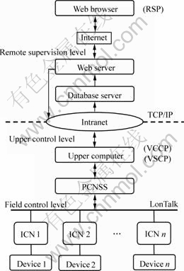
Fig. 1 Architecture of NCSS
The field control level mainly contains ICNs, each of which is connected to the devices. It runs applications independently to carry out control tasks, and comm. unicates with upper-level computer and other ICNs over fieldbus, using LonTalk that is the LonWorks network protocol.
At the upper control level, the software platforms VCCP and VSCP are installed on the upper-level computer. Besides a usual network card, there is another one named PCNSS on the upper-level computer, which is especially for communicating with the ICNs on LonWorks fieldbus.
At the remote supervision level, the Intranet/ Internet-based RSP uses a B/S structure mode with three levels: a database server, a Web server and a Web browser. The database and Web servers communicate with the upper-level computer over Intranet by means of the TCP/IP protocol. Remote supervision is carried out on the RSP by using the Web browsers over the Internet.
2.2 Main features
The NCSS has several important features.
1) A universal ICN provides digital input (DI), digital output (DO), analog input (AI), and analog output (AO) channels, and a communication interface based on the LonWorks standard. It can be connected directly to all kinds of digital/analog device, other ICNs, and the upper-level computer through PCNSS network card.
2) The VCCP provides the visual control con- figuration functions for the ICNs, which has many function blocks that carry out a number of basic and advanced control algorithms. The graphic configuration manner of the VCCP is very simple and makes it unnecessary to program the ICNs using the Neuron C��the program language specially for LonWorks.
3) The VSCP provides the visual supervision configuration functions for the real-time monitoring of processes. These functions include the creation of process diagrams, tables, curves and databases, database manipulation, and real-time communications.
4) The RSP is used to remotely supervise process control system over Intranet/Internet in real-time.
The NCSS developed in this study is a basic system, and it is an open system with good flexibility. Using it as a foundation, various types of process control and supervision systems can be constructed to meet a variety of needs.
3 Design of networked control and super-
vision system(NCSS)
The design of a NCSS involves the design of hardware and software. The main piece of hardware is the universal intelligent control node (ICN), which contains a circuit board with the basic LonWorks components and modular I/O channels. An ICN can be connected directly to all kinds of devices, such as sensors or actuators, and also to other ICNs. The software includes the VCCP, VSCP and RSP. The visual graphic block manner of the VCCP and VSCP simplifies the tedious work of programming, and the users are not required to have a thorough grasp of great knowledge about hardware and Neuron C language. So it is significantly reduced the cost and development time of a control system. Furthermore, the RSP developed using Web technologies makes it ease to implement the remote supervision of industrial progresses through Intranet/ Internet.
3.1 Intelligent control node (ICN)
The architecture of an ICN is shown in Fig.2. It mainly contains a TMPN3150B1AF Neuron chip, which is the most important chip of the ICN to carry out control tasks at the field level. The FTT-10A module is a transceiver, by which ICN communicates over LonWorks network using the LonTalk protocol. There are an 8-channel AI/AO module and a 4-channel DI/DO module, which are the input-output interfaces to external sensors and actuators embedded in an ICN, and which can be used depending on the style of devices to which it is connected. Each AI/AO channel has an input and output range of either 1-5 V or 4-20 mA (set with a jumper wire). The ICN automatically identifies the type of I/O module when it is turned on and has a plug-and- play function. Signals from outside are fed to the I/O pins of the Neuron chip via the AI and DI channels. The EPROM and the nonvolatile RAM (NVRAM) are the storage devices of ICN.
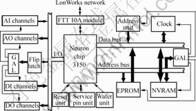
Fig.2 Architecture of ICN
3.2 Visual control configuration platform (VCCP)
The NodeBuilder is a kind of tool software of LonWorks[14], which is used to develop, compile and debug the control code for an ICN and to download it to the ICN. However, in practice, it is quite difficult to program and maintain thousands of ICNs by this method. The VCCP developed is helpful for overcoming the obstacle.
The functional architecture of the VCCP is shown in Fig.3. It integrates a graphic programming environment and network management into a single package, which has three main functions: graph configuration, graph editing and real-time control. The VCCP consists of 29 types of control blocks and 5 types of line blocks as well, which provides a convenient configuration editing interface and a library of function blocks, and users only need to click and drag blocks, and connect them with the mouse, as in CAD. Users can also use the graph editing function to add, delete and correct the VCCP diagram files visually and easily. The real-time control function enables users to download the control configuration diagrams to the given ICNs and run them at any time, and to download and modify the parameters online.
The technology involved in the real-time control function includes communication over LonWorks fieldbus. The communication module of the VCCP employs a set of special communication rules. The data structure of the communication parameters is defined to form a frame. The master/slave response mode for communication services is mainly used to send control configuration programs from the VCCP to ICNs in order to control their operation.
In this study, the maximum length of a data packet was set to 45 bytes in consideration of the restrictions on transmission time and the size of messages. Every packet is comprised of 6 components: message code (Code), node address code (NodeAddr), command code (Cmd), configuration parameter data (Data), packet sequence code (PacketNo), and check code (Check).
The possible values of each component are as follows.
1) Code
0: Packet from upper-level computer;
1: Packet from local node.
2) NodeAddr
The address of the node to which the packet will be sent.
3) Cmd
1: The packet contains parameters;
2: The packet contains operating commands.
4) PacketNo
The sequence number of the packet, and number 255 means that no packet is received.
5) Data
Configuration parameters and information data.
6) Check
Check code.
3.3 Visual supervision configuration platform (VSCP)
The VSCP is a visual, multifunctional drawing, supervising and graphic configuration platform for LonWorks fieldbus developers, which provides graph control and editing functions that enable supervision of the real-time operation of the system. The main functions include drawing history trend graphs, plotting real-time curves, making data reports, and producing warning signals by means of multiple media, such as sounds and lights. The functional architecture of the VSCP is shown in Fig.4.

Fig. 3 Functional architecture of VCCP
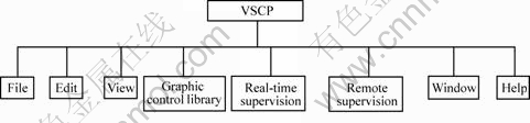
Fig.4 Functional architecture of VSCP
The graph controls of the VSCP are used to represent common control objects, which makes it easy for users to draw supervision diagrams. There are two types of graph controls: static and dynamic. The former handles the static information that is unrelated to the database, such as all the pipe controls for various directions, while the latter handles dynamic information that changes from moment to moment in association with the database. Dynamic graphs use real-time data, such as the real-time operational data, the real-rime control laws. The CAD mode of the graph editing function supports both a general graph editing function, just as general drawing software does, and a real-time on-line editing function. The real-time supervision function is used to display real-time data supervised in several display modes, i.e. datasheet, curve and common graph. The remote supervision function can realize the transmission of data from and to a remote computer through Intranet/Internet.
3.4 Remote supervision platform (RSP)
In this paper the Intranet/Internet-based RSP employed a three-layer B/S structure mode for the remote supervision design, consists of a browser, a Web server and a Web database. In this architecture, all complex tasks are carried out on the Web server, and only the results are presented on the client computer with the Web browsers. As a result, it simplifies the requirements for a client machine, reduces the time needed for software development, and makes the client computer easy to operate, maintain and upgrade.
The first requirement for a RSP is the establishment of a robust channel between the upper-level computer and the database server using the TCP/IP protocol and programmed sockets. It is completed in two steps. First, the upper-level computer sends a connection request to the database server. Then, the database server sends a confirmation back to the upper-level computer after the request has been received. Once a robust channel has been established, the upper-level computer sends the real-time data to database server, which checks and stores it in a database.
The Web and database servers are connected using an ActiveX data object (ADO)[15].
For new data on the field presented to the client computer timely, the Web page is refreshed dynamically. The update period could be set flexibly according to the demands of the situation. Different update periods were tested experimentally, and the best one was found to be about 2 s.
Every time the Web page is refreshed, the browser requests new data from the Web server. In order to avoid screen blinking caused by refreshing too frequently, frame Web page technology and cookie technology were introduced. Every time the browser requests data from the Web server, a frame Web page, which consists of two Web pages, e.g. pages A and B, is sent from the server to the browser. On the client computer page A is shown and acquires data from cookies. Page B works as a Daemon and is transparent to the users, which requests data from the server and stores them in cookies on the hard disk of the client computer. This frame Web page is easily implemented in HTML.
4 Laboratory experiment
The NCSS was used for the control and supervision of the pressure and flow systems in our laboratory. The distance between the upper-level computer and the ICNs was about 15 m. They were connected with twisted-pair cables and network card PCNSS. No special criteria were used in the selection of the client computers, which were connected to the Web server over the internet or the campus network, and the Web server, the database server and the upper-level computer over the campus network.
The experiment system architecture is shown in Fig.5. The ICN 1 and ICN 2 controlled the pressure and flow subsystems, respectively. The upper-level computer controlled and supervised both subsystems after the control system configuration was constructed. In addition, the flow control subsystem was also designed to link the pressure subsystem as follows.
1) When the pressure in subsystem 1 was less than 15 kPa, valve 1 in subsystem 2 was set to 60% open (flow rate: 50.0 L/h).
2) When the pressure in subsystem 1 was lager than 15 kPa, valve 1 in subsystem 2 was adjusted to 40% open (flow rate: 33.3 L/h).
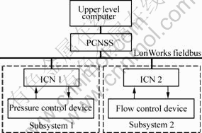
Fig.5 Architecture of laboratory experiment system of pressure and flow
Conventional control methods rely mainly on single-node control. Since all the control information has to pass through the upper-level computer, it not only takes a long time, but also puts a heavy load on that computer. In contrast, interlocking control between ICNs provides great advantages regarding these points since information can be exchanged among ICNs via network.
In the system, the pressure of subsystem 1 determines the flow rate of subsystem 2. The pressure information is transferred from ICN 1 to ICN 2 directly, not via the upper-level computer. When the pressure of subsystem 1 reaches the target value of 15 kPa, the valve in subsystem 2 is closed to some degree so as to reduce the flow rate FT1.
The VCCP and the VSCP were used to construct the control and supervision configurations for ICNs 1 and 2. Graphs of the measured data and pictures for monitoring were displayed on the VSCP platform in the upper-level computer.
The measured curves are shown in Fig.6 and the experimental procedure is as follows.
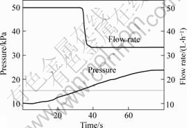
Fig.6 Measured curves of pressure and flow rate
Step 1 The flow rate of subsystem 2 was first set to 50.0 L/h.
Step 2 The pressure valve was opened using the control configuration in the upper-level computer in order to increase the pressure of subsystem 1. The pressure is supervised from the monitor screen of the upper-level computer. Fig.6 shows that the pressure increases gradually from the initial value, which is less than 10 kPa.
Step 3 When the pressure reached 15 kPa, this information was sent to ICN 2 directly from ICN 1, and subsystem 2 closed valve 1 somewhat to reduce the flow rate. It is clear from Fig.6 that the flow rate drops sharply 4 s later (the time-delay in the flow subsystem is 4 s), and finally settles at 33.3 L/h, as designed.
Step 4 The pressure of subsystem 1 kept increasing both during the transient response and in the steady state of the flow rate. When the pressure finally settled at 23 kPa, the valve was closed and the pressure was maintained at the target value.
To watch the flow control device on a client computer, the users can input the IP address into the browsers, and the Web page with the experimental data and curves will appear, as shown in Fig.6. The data and curves on the Web page are dynamic and are updated with the real-time sampling data in the upper-level computer. An authorized user can also modify the parameters and control the ICNs remotely online.
The following results were obtained from the experiment.
1) The pressure and flow control subsystems can be easily configured using the VCCP. No programming is needed.
2) The hardware of the ICNs works properly.
3) The information is transferred correctly between an ICN and the upper-level computer to control a single node.
4) Information is correctly transferred between the ICNs to carry out interlocking control.
5) Real-time information is properly displayed on the upper-level computer in the form of curves, tables, etc. by means of the VSCP platform.
6) Information is correctly transferred among the ICNs, the upper-level computer, the Web and database servers and the client computers to carry out supervision.
5 Conclusions
1) NCSS based on LonWorks fieldbus and Intranet/Internet was presented.
2) The NCSS provides the function of real-time control, configurations and remote supervision.
3) The advantages of the NCSS make the users save plenty of time in the development of networked control systems, reduce overall design costs and more easily work with LonWorks technology.
References[1] CAVALIERI S, PANNO D. A novel solution to interconnect fieldbus systems using IEEE wireless LAN technology[J]. Computer Standards and Interfaces, 1998, 20(1): 9-23.
[2] THOMESSE J P. Fieldbus and interoperability[J]. Control Engineering Practice, 1999, 7(1): 81-94.
[3] TIAN G Y, ZHAO Z X, BAINES R W. A fieldbus-based intelligent sensor[J]. Mechatronics, 2000, 10(8): 835-849.
[4] PATZKE R. Fieldbus basics[J]. Computer Standards and Interfaces, 1998, 19(5/6): 275-293.
[5] YANG Xian-hui. Technology and Application of the Fieldbus[M]. Beijing: Tsinghua University Press, 1999.(in Chinese)
[6] ZHANG Ying, QIAN Jun, CHI Yu-dong, et al. LonWorks and its application on industrial control[J]. Control and Instruments in chemical Industry, 1998, 25(5): 44-47. (in Chinese)
[7] TSE W L, CHAN W L, LAI S S. Emergency lighting monitoring system using LonWorks[J]. Automation in Construction, 2003, 12(5): 617-629.
[8] MAHALIK N G P C, LEE S K. A study on production line automation with LonWorks control networks[J]. Computer Standards and Interfaces, 2002, 24(1): 21-27.
[9] LAZARO J L, GARCIA J C, MAZO M, et al. Distributed architecture for control and path planning of autonomous vehicles[J]. Microprocessors and Microsystems, 2001, 25(3): 159-166.
[10] MITCHELL B W. Distributed LonWorks control and monitoring system for environment and security[J]. Applied Engineering in Agriculture, 1999, 15(4): 345-350.
[11] HU Guo-xiong, LU Ling, HUANG Li. Development of substation automation based on the LonWorks control system technology[J]. Proceedings of the Chinese Society of Universities for Electric Power System and Automation, 2005, 17(1): 83-87.(in Chinese)
[12] QIAN Xue-jun, GENG Xiao-qing. Supervision and control system of train��s safe electricity based on LonWorks technology[J]. Journal of Tongji University: Natural Science, 2005, 33(1): 116-120.(in Chinese)
[13] Echelon Corp. Neuron C Programmer��s Guide[M]. 4th ed. California: Echelon Corporation, 1995.
[14] Echelon Corp. NodeBuilder User��s Guide[M]. California: Echelon Corporation, 1995.
[15] CHEN Duan-sheng, WU Yang-yang. Using API to develop Web database system middle-ware techniques[J]. Computer Application, 1999, 19(4): 15-18.(in Chinese)
Foundation item: Project (60425310) supported by the National Natural Science Foundation of China; Project(2006AA04Z172) supported by the High-Tech Research and Development Program of China
Received date: 2006-06-24; Accepted date: 2006-07-27
Corresponding author: WU min, Professor; Tel: +86-731-8836091; Fax: +86-731-8836091; E-mail: min@mail.csu.edu.cn
(Edited by LI Xiang-qun)
Abstract: A networked control and supervision system (NCSS) based on LonWorks fieldbus and Intranet/Internet was designed, which was composed of the universal intelligent control nodes (ICNs), the visual control and supervision configuration platforms (VCCP and VSCP) and an Intranet/Internet-based remote supervision platform (RSP). The ICNs were connected to field devices, such as sensors, actuators and controllers. The VCCP and VSCP were implemented by means of a graphical programming environment and network management so as to simplify the tasks of programming and maintaining the ICNs. The RSP was employed to perform the remote supervision function, which was based on a three-layer browser/server(B/S) structure mode. The validity of the NCSS was demonstrated by laboratory experiments.
[2] THOMESSE J P. Fieldbus and interoperability[J]. Control Engineering Practice, 1999, 7(1): 81-94.
[4] PATZKE R. Fieldbus basics[J]. Computer Standards and Interfaces, 1998, 19(5/6): 275-293.
[13] Echelon Corp. Neuron C Programmer��s Guide[M]. 4th ed. California: Echelon Corporation, 1995.
[14] Echelon Corp. NodeBuilder User��s Guide[M]. California: Echelon Corporation, 1995.
