
J. Cent. South Univ. Technol. (2007)06-0808-06
DOI: 10.1007/s11771-007-0154-5
![]()
FEM modeling for 3D dynamic analysis of deep-ocean mining pipeline and its experimental verification
WANG Gang(�� ��), LIU Shao-jun(���پ�), LI Li(�� ��)
(School of Mechanical and Electrical Engineering, Central South University, Changsha 410083, China)
Abstract��3D dynamic analysis models of 1000 m deep-ocean mining pipeline, including steel lift pipe, pump, buffer and flexible hose, were established by finite element method (FEM). The coupling effect of steel lift pipe and flexible hose, and main external loads of pipeline were considered in the models, such as gravity, buoyancy, hydrodynamic forces, internal and external fluid pressures, concentrated suspension buoyancy on the flexible hose, torsional moment and axial force induced by pump working. Some relevant FEM models and solution techniques were developed, according to various 3D transient behaviors of integrated deep-ocean mining pipeline, including towing motions of track-keeping operation and launch process of pipeline. Meanwhile, an experimental verification system in towing water tank that had similar characteristics of designed mining pipeline was developed to verify the accuracy of the FEM models and dynamic simulation. The experiment results show that the experimental records and simulation results of stress of pipe are coincided. Based on the further simulations of 1 000 m deep-ocean mining pipeline, the simulation results show that, to form configuration of a saddle shape, the total concentrated suspension buoyancy of flexible hose should be 95%-105% of the gravity of flexible hose in water, the first suspension point occupies 1/3 of the total buoyancy, and the second suspension point occupies 2/3 of the total buoyancy. When towing velocity of mining system is less than 0.5 m/s, the towing track of buffer is coincided with the setting route of ship on the whole and the configuration of flexible hose is also kept well.
Key words:
deep-ocean mining; pipeline modeling; dynamic analysis; finite element method��
1 Introduction
Chinese poly-metallic nodule deep-ocean mining system consists of a seafloor miner, a flexible hose, a buffer station, lift pipe and pump, and a surface ship. Its constitution is similar to the deep-ocean mining systems of other countries, one of which was tested successfully by OMI in 1978 in the North Pacific Ocean with 5 000 m depth[1-3]. Some research groups have developed the software for the position-control and dynamic simulation of mining system[4-7]. CHUNG presented the FEM modeling and solution techniques of nonlinear static analysis of deep-ocean mining pipe and given some numerical studies for an 5 486 m pipe modeled by 3D beam finite elements that included coupled axial, bending and torsional deformations[8-9]. Further FEM modeling and numerical analyses of 3D nonlinear coupled static state as well as dynamic behavior of 6000 m pipe and attachments were found in later publications[10-11]. Moreover, MUSTOE et al[12], HUTTELMAIER et al[13] and CHENG et al[14] used the discrete element method (DEM) to simulate deep-ocean pipe.
During the mining process��the lift pipeline bears complex nonlinear coupled external loads, such as gravity, buoyancy, hydrodynamic loads, internal and
external fluid pressures, torsional moment and axial force induced by pump working, concentrated buoyancy on the flexible hose, etc. Furthermore, lift pipeline, including flexible hose and steel pipe, has geometric nonlinear deformation. Thus, modeling methods and solution techniques of simulation are very important for deep-ocean mining pipeline, especially in transient dynamic analysis. In some earlier researches, steel pipe and flexible hose were simulated respectively, which applied static method to calculate initial configuration of pipeline model and did not consider the coupling effect of steel pipe and flexible hose[15-17]. In this work, to investigate 3D transient behaviors of integrated deep-ocean mining pipeline of Chinese 1000 m sea trial project, the analysis models of integrated pipeline were established by FEM. Some modeling methods and solution techniques of dynamic simulation and external loads of pipeline were given. Meanwhile, a verification experiment in towing water tank was presented to verify the accuracy of the FEM modeling and dynamic simulation.
2 FEM modeling
2.1 Configuration of mining pipeline
According to the project of Chinese 1 km sea trial for deep-ocean mining system, the mining pipeline consists of lift steel pipe, pump, a buffer station and flexible hose, which is fixed with 1-3 cables outside. Compared with other country��s mining pipeline, it has special configuration of saddle shape (shown in Fig.1): 400 m flexible hose connects the buffer and miner. To provide concentrated buoyancy, some buoyancy balls bound together are attached with the flexible hose at two points, which makes the flexible hose form a saddle shape near the seafloor. This special configuration of flexible hose is considered not only to compensate the small height changing of the seafloor, but also to make less counter force of the miner. In order to simulate 3D transient behaviors of the integrated deep-ocean mining pipeline considering the nonlinear large deformation of flexible hose, it is necessary to establish the model of integrated pipeline by FEM and adopt proper solution techniques.

Fig.1 Schematic diagram of mining pipeline of 1 000 m sea trial
2.2 FEM models and simulation techniques
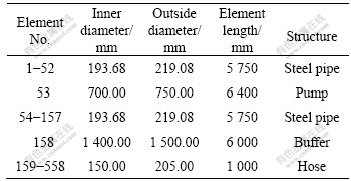
The FEM model of integrated pipeline is established in ANSYS. The pipe element is based on the 3D beam element and includes simplifications due to its symmetry and standard pipe geometry. Thus, the pipe element is uniaxial element with tension, compression, torsion, and bending capabilities, and it has two nodes. Each node has six degrees of freedom: translations along x, y and z directions and rotations about x, y and z axes. The FEM model of the integrated pipeline consists of steel pipe, pump, buffer station, and flexible hose, in which cables are looked as added mass of each part of pipeline. The flexible hose is divided into 400 elements (1 m per element); the steel pipe is divided into 156 elements (5.75 m per element); the pump is regarded as one element; and so does the buffer station. Element division and some parameters of pipeline are shown in Table 1.
Table 1 Element division of pipeline
In the global coordinate system of��pipeline model as shown in Fig.2, the direction of water depth is parallel to the global z-axis, and virtual sea surface is the x-y plane(z=0). The global origin is located at the joint of the steel pipe and the heave compensation platform, as the point A of FEM model I in Fig.2.
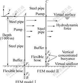
Fig.2 FEM models of integrated pipeline for different motion��s simulation
In real sea trial system, the top end of steel pipe is connected to the heave compensation platform of mining ship by a ball and socket joint, whose rotation of z-axis is restrained particularly. The buffer station is connected to the bottom of the steel pipe by a cross connection. The top end and bottom of the flexible hose are connected to the buffer station and self-propelled miner respectively by firm joint. Thus, in FEM model, the constraint relations of degree of freedom are used to define these joints, such as the connection of the buffer station, and steel pipe is defined as several coupled degrees of freedom. To simulate the towing��motion of integrated pipeline, the motion of mining ship(the top end of steel pipe) and self-propelled miner(the bottom of flexible hose) are simplified to 2D or 3D point-motions, which are loaded as the boundary conditions of pipeline.
To simulate 3D transient motions of integrated pipeline, it is necessary to carry out the simulation for initial configuration of pipeline model firstly. In this paper, dynamic method is used to calculate initial configuration of pipeline model. According to different 3D transient motions, different initial FEM models have been set up, as shown in Fig.2.
FEM model I: The initial FEM model I was applied to simulating the configuration of pipeline and the towing motions of track-keeping operation. The initial FEM model of whole pipe system is a vertical pipeline, and the total height is 1 309.4 m. For the virtual seafloor is the plane at z= -1 000 m, the 309.4 m length of hose is below the virtual seafloor initially. The simulation for initial configuration is to simulate the shaping process of saddle shape of flexible hose based on integrated pipeline model. Thus, during the simulation process of FEM model I, the bottom of flexible hose at the point B(x=0, y = 0, z= -1309.4 m) should be lift up and move to the point (x=200 m, y=0, z= -1 000 m). Linear ramped load is used in this process, in which load time is 200 s and integration time step is 0.01 s.
FEM model II: The initial FEM model II is applied to simulating the launch motion, which is in the period from the miner landing the seafloor to the steel pipe launching completely. In this course, the configuration of flexible hose changes from a vertical pipeline to a saddle shape. To ensure the continuity of the simulation, the initial FEM model II is also a vertical pipeline (1309.4 m), the top of steel pipe is at the point C (x=0, y=0, z=309.4 m) and the bottom of flexible hose is just at the virtual seafloor (point D: x=0, y=0, z= -1 000 m). All degrees of freedom of the elements above the virtual sea surface (1-54 elements) are restrained initially. When the simulation of launch executes, those 54 elements move downwards to the virtual sea with whole pipeline step by step, and x-axis and y-axis degrees of freedom of those elements will be released one by one. In order to form a good saddle shape of the flexible hose, the miner should move a short distance (10 m or 15 m) after each steel pipe launch from the ship. The speed of the seafloor miner adopted in the simulation is 0.5 m/s, and the launch speed of steel pipe adopted in the simulation is 0.575 m/s.
The material of the steel pipe is P110. The mass of the cables and the steel joints of steel pipes and hoses are also considered as the added mass of pipe element in the FEM models. The flexible hose is a kind of composite material pipe that is very difficult to model. So the macroscopic properties of flexible hose are adopted in the model. According to correlative researches of flexible hose, the following property parameters of flexible hose are assumed: tensile rigidity is 1.536��109 N, bending stiffness is 2.096��104 N��m2, torsional rigidity is 1.03��104 N��m2, the total mass of hose in water is 12 t.
The corotational formulation presented by Rankin and Brogan is adopted to describing the geometric nonlinearities of structural model that includes large rotations and small mechanical strains[18].
The motion equation of structure model for dynamic simulation is represented by
![]() (1)
(1)
where M is the mass matrix; K is the stiffness matrix; C is the structural damp matrix; {u}is the node displacement vector; F(t) represents all external force vectors.
2.3 External loads
In FEM model of pipeline, the following external loads are considered: gravity, buoyancy, hydrodynamic forces, internal and external fluid pressures, torsional moment and axial force induced by pump working, concentrated suspension buoyancy on the flexible hose. The concentrated suspension buoyancy on the flexible hose provided by concentrated buoyancy balls is considered as the constant force with the direction of z-axis, which makes the flexible hose form a saddle shape during the launch. According to the design of the flexible hose, a kind of skeleton structure surrounded flexible hose is applied to connecting the concentrated buoyancy balls at two positions. The skeleton structure with the length of 10 m can avoid stress concentration. Therefore, the concentrated buoyancy at each position is distributed along 10 elements of flexible hose in FEM model.
In order to load the hydrodynamic forces, the Morison��s equation is used to calculate the distributed hydrodynamic force per unit length on the pipeline:
![]()
![]() (2)
(2)
where Fd is the vector of hydrodynamic force per unit length; CD is normal drag coefficient; ��W is water density; d is outer diameter of the pipe; vn is normal relative water particle velocity vector; ![]() is normal water particle acceleration vector; CM is inertia coefficient; CT is tangential drag coefficient; vt is tangential relative water particle velocity vector.
is normal water particle acceleration vector; CM is inertia coefficient; CT is tangential drag coefficient; vt is tangential relative water particle velocity vector.
The drag coefficients CD and CT are related to the Reynolds number Re, meanwhile, the Reynolds number varies with the fluid-pipe relative velocity, so the hydrodynamic force of pipeline is related to fluid-pipe coupling.
![]() (3)
(3)
where ��W is seawater viscosity being as a constant 1.5��10-6 m2/s along the 1 000 m depth. Therefore, two factors affect the drag coefficients by verification of hydrodynamic experiments: 1) the configuration of the pipeline at different positions; 2) the typical hydrodynamic angle of attack of each part of pipeline during the towing motion. Based on correlative experiment researches, the variation range of CD is 0.5-1.5, that of CT is 0.01-0.03.
Small amplitude airy wave theory was selected to calculate wave velocity potential:
![]() (4)
(4)
where H is wave height; g is acceleration of gravity; k is wavenumber; d is water depth; C is waveform velocity (c=L/T, L is wave length, T is wave period).
The marine conditions in simulation are assumed as follows: wave height is 2.5 m, surge period is 10 s; velocity of current on surface is 0.77 m/s; velocity of current at bottom is 0.15 m/s; ocean current is oriented along the global x-axis. The velocity of current from surface to bottom is
![]() (5)
(5)
where d is the water depth, ranging from 0 to �C1 000 m.
The wave-induced motion of ship (top end of steel pipe) along z-axis is simplified as point-motion as:
![]() (6)
(6)
Eqn.(6) is loaded as the boundary conditions of the FEM model.
3 Verification experiment
It is difficult to evaluate the accuracy of the simulation by an experimental model based on similarity principle, because of the variety of the drag coefficients CD, CT and the proportion of the diameter to the length of pipeline. Therefore, an experimental system in towing water tank, which is similar to 1 000 m mining pipeline, is developed to verify the accuracy of FEM model and dynamic analysis. The experimental model in towing water tank is shown in Fig.3, including a steel pipe with 6.2 m in length and 3.5 cm in outside diameter and 1 mm in thickness, a 20 kg steel mass, a flexible hose with 6 m in length and 5 cm in outside diameter and 1 cm in thickness, two buoyancy structure surrounding the hose, a top motion vehicle and a bottom motion vehicle. The strain gauges are fixed on several positions of the steel pipe.
The periodic motions of top end of steel pipe along the vertical direction and the horizontal direction are generated by the top motion vehicle. The motion amplitude of the vertical direction is 10 cm, and that of the horizontal direction is 50 cm. The frequencies of top motions are adjusted by the frequency converters of the electromotor. The bottom motion vehicle makes the motion only along the horizontal direction with the amplitude of 10 cm. The joint type of each part of experimental pipe system is the same as that of the 1 000 m sea trial system. The whole experimental model is fixed on a towing apparatus in towing water tank. The motion velocity of the towing apparatus can be changed to realize different velocities of water current.

Fig.3 Verification experiment system in towing water tank
According to the experimental model in towing water tank and its motion, the FEM model is established by the same modeling methods and its dynamic simulation is performed. In experimental measurement, the initial value of static strain of pipe is difficult to be measured accurately, so the static measurement results do not represent static strain of pipe. Then, the differential value of dynamic response and static response is used as the dynamic measurement results compared with the results of FEM simulation��as well as the video records of configuration of pipe. The representative strain curves of measuring points are transformed to the dynamic deforming stress shown in Fig.4, which are much coincided with the FEM simulation results shown in Fig.5. In this case, the towing velocity is 0.3 m/s, and the period of top motion is 10 s, and the bottom motion vehicle is relatively stationary.
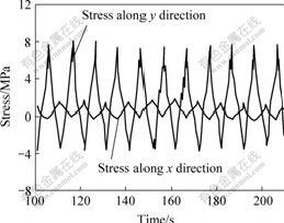
Fig.4 Experimental records of stress of steel pipe
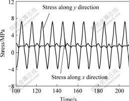
Fig.5 Calculated results of stress by FEM program
4 Simulation results
The configurations of pipeline reflect the mechanical states of system and affect the transportation of inner pulp. Some concentrated buoyancy balls suspended on the hose provide proper buoyancy to make the flexible hose form a saddle shape near the seafloor. Arrangement of concentrated buoyancy and movement state are two important factors for pipeline configuration, especially for the configuration of flexible hose.
Curve 1 in Fig.6 is the initial configuration of 400 m flexible hose based on FEM model I. In this case, the total concentrated buoyancy is equal to the weight of flexible hose in water. The conclusion drawn from a series of simulation is that the proper value of the total concentrated buoyancy ranges between 95% and 105% of the weight of flexible hose in water; the first suspension point occupies 1/3 of the total buoyancy, and the second suspension point occupies 2/3 of the total buoyancy; the length of hose between the first suspension point and the buffer is 133 m, and the length of hose between the second suspension point and the buffer is 267 m.

Fig.6 Transformation of shape of flexible hose due to movement of miner
1��t=0 s; 2��t=25 s; 3��t=50 s; 4��t=75 s; 5��t=100 s;
6��t=125 s; 7��t=150 s; 8��t=175 s; 9��t=200 s;
When the self-propelled miner moves at 0.5 m/s along negative direction of x-axis on seafloor, dynamic deformation results of the configuration of flexible hose are shown as curves 1-9 in Fig.6.
Track-keeping motion of integrated mining system is a basic mode of towing operation in deep-sea mining[3, 5]. According to Chinese sea trial project, the ship moves along the setting route, and the miner moves along the ship��s track with the same velocity. In towing motions of track-keeping, the deformation of steel pipe and the reaction forces of joints should be restricted within narrow limits to maintain the stability of pipeline. The straight-line movement and turning of the integrated mining system are basic motions of towing motion. Towing motions for setting route and its simulation results of pipeline are shown in Fig.7. In this case, the towing velocity and the miner velocity are 0.5 m/s, the miner moves along the ship��s track and the distance between the ship and miner along setting route is kept at 200 m. It is shown in Fig.7 that the towing track of the buffer is coincided with the setting route on the whole. Meanwhile, the track of the midpoint of the hose differs
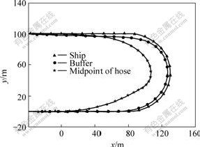
Fig.7 Simulation results of towing motion of track-keeping
from the setting route when the turning radius of ship and miner is 50 m. According to the simulation results of towing motion in Fig.7, the calculated results of the counter forces of the top end of pipeline are shown in Fig.8, which fluctuate with the turning of ship.
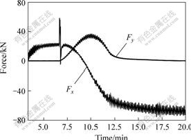
Fig.8 Reaction force of top end of pipeline during towing motion
5 Conclusions
1) To simulate different 3D transient motions of the integrated deep-ocean mining pipeline, different initial FEM models as FEM model I and FEM model II are set up. Morison��s equation and small amplitude Airy wave theory are adopted to calculating the distribution of hydrodynamic forces on pipeline.
2) An experimental model in towing water tank with the similar characters of pipe system of 1 000 m sea trial is put forward to verify the FEM modeling and accuracy of the dynamic analysis. The simulation results of stress of steel pipe are coincided with the measurement records.
3) Based on FEM simulation of integrated pipeline, some essential characteristic and transient behaviors of motions of pipeline are investigated. Otherwise, the velocity and direction of current from surface to bottom is assumed as ideal value, and the changes of local flow field due to the outside structure of pipeline are not considered in FEM model, which may influence the simulation results to some extent.
Acknowledgements
The authors thank China Ship Scientific Research Center for assistance of the hydrodynamic experiments.
References
[1] BATH A R. Deep sea mining technology: Recent developments and future projects[C]// Offshore Technology Conference, 21st Houston. Texas: Paper No. OTC 5998, 1989: 333-340.
[2] CHUNG J S. Deep-ocean mining issues and ocean mining working group[C]// Proceedings of the 3rd Ocean Mining Symposium. Goa India: ISOPE, 1999: 14-20.
[3] LIU Shao-jun, WANG Gang, LI Li. Virtual reality research of ocean poly-metallic nodule mining based on COMRA��s mining system[C]// Proceedings of the 5th Ocean Mining Symposium. Tsukuba, Japan: ISOPE, 2003: 104-110.
[4] CHUNG J S. Deep-ocean mining technology: Learning curve I[C]// Proceedings of the 5th Ocean Mining Symposium. Tsukuba, Japan: ISOPE, 2003: 1-5.
[5] CHUNG J S. Track-keeping control of seafloor miner by successive learning of unknown velocity and soil properties[C]// Proceedings of the 3rd Ocean Mining Symposium. Goa, India: ISOPE, 1999: 85-92.
[6] BRINK A W��CHUNG J S. Automatic position control of a 300 000 tons ship during ocean mining operations[C]// Offshore Technology Conference. Paper No. OTC 4091, 1981: 205-224.
[7] CHUNG J S, WHITE A K, LODEN W A. Nonlinear transient motion of deep ocean mining pipe[J]. Journal of Energy Resources Technology, 1981, 103(3): 2-10.
[8] FELIPPA C A, CHUNG J S. Nonlinear static analysis of deep ocean mining pipe��Part��: Modeling and formulation[J]. Journal of Energy Resources Technology, 1981, 103(3): 11-15.
[9] CHUNG J S, FELIPPA C A. Nonlinear static analysis of deep ocean mining pipe��Part��: Numerical studies[J]. Journal of Energy Resources Technology, 1981, 103(3): 16-25.
[10] CHUNG J S, CHENG B R, HUTTELMAIER H P. Three- dimensional coupled responses of a vertical deep-ocean pipe: Part I. Excitation at pipe ends and external torsion[J]. International Journal of Offshore and Polar Engineering, 1994, 4(4): 320-330.
[11] CHUNG J S, CHENG B R, HUTTELMAIER H P. Three- dimensional coupled responses of a vertical deep-ocean pipe: Part II. Excitation at pipe top and external torsion[J]. International Journal of Offshore and Polar Engineering, 1994, 4(4): 331-339.
[12] MUSTOE G G , HETTELMAIER H P, CHUNG J S. Assessment of dynamic coupled bending-axial effects for two-dimensional deep-ocean pipes by the discrete element method[J]. International Journal of Offshore and Polar Engineering, 1992, 2(4): 289-296.
[13] HUTTELMAIER H P, CHUNG J S, MUSTOE G G, et al. Eigenvalues of a long vertical pipe by DEM, FEM and exact solution[C]// Proceedings of the 3rd International Offshore and Polar Engineering Conference, 1993: 311-314.
[14] CHENG Bao-rong, ZH tor method for dynamic analysis in the 3-D beam structure[J]. ENG Zhao-chang. Discrete element with flexible connecJournal of Tsinghua University, 1996, 36(3): 12-17. (in Chinese)
[15] JIAN Qu, HE Yong-sen, WANG Ming-he. Numerical study of dynamic behavior of flexible pipes in deep sea mining[J]. Ocean Engineering, 2001, 19(2): 59-64. (in Chinese)
[16] GUO Xiao-gang. Nonlinear dynamic modeling of the fluid-solid- coupled flexible pipe systems for deep sea mining[J]. Engineering Mechanics, 2000, 17(3): 93-104. (in Chinese)
[17] XIAO Lin-jing. The study on kinematic and dynamic characteristics of lift pipe in deep ocean mining[D]. Beijing: Beijing University of Science and Technology, 2000: 8-50. (in Chinese)
[18] RANKIN C C, BROGAN F A. An element independent corotational procedure for the treatment of large rotations[J]. Journal of Pressure Vessel Technology, 1986, 108: 165-174.
Foundation item: Project(DY105-3-2-2) supported by China Ocean Mineral Resources Research and Development Association(COMRA); Project(50675226) supported by the National Natural Science Foundation of China
Received date: 2006-10-15; Accepted date: 2007-03-28
Corresponding author: WANG Gang, Doctoral candidate, Associate professor; Tel: +86-731-8830365; E-mail: wg@mail.csu.edu.cn
