
������ʱ��: 2019-06-06 11:30
CuNi14Al3�Ͻ��������Ĺ�����ȱ���о�
������ͨ��ѧ���Ͽ�ѧ�빤��ѧԺ��������ǿ�ȹ����ص�ʵ�����ɳ߶Ȳ�����Ϊ�о�����
����˹���²��Ϲɷ�����˾
ժ Ҫ��
CuNi14Al3�Ͻ�������ͨ��������������죬ȥӦ���˻�ȹ����Ʊ����ɡ����������չ����г������������⣺�����������������ǰȥ�����Ͻ϶ࣻ���쿪�ѣ���Ʒ������̽�˵��������Ƶ�ȱ�ݡ����о����ý���������OM����ɨ��羵��SEM������羵��TEM���������ǣ�EDS���Լ�ά��Ӳ���ǵȶ�CuNi14Al3�Ͻ�������ÿһ���ӹ����պ������֯�����ܽ��жԱȷ������۲쵽�����Ʊ���������Ҫ�����������ȱ�ݣ��ֱ����������ɷ�ƫ�����쾧��֯�Լ����ơ��о������ʾ����һϵ�й�����ȱ�ݵIJ��������ںϽ���������ԣ���������ʱ�䡢����˳���Լ����������ȣ�ʹ��ԭʼ��̬�Ͻ�֦����֯�ִ�һ��֦������ɴ�10 mm���ϣ���֦��ƫ�������������أ�ͨ�������ȼӹ�����Щȱ��δ�ܵõ���ȫ������������һ���γɻ쾧��֯�����Ƶȡ��о�������Ҫ����������������ȱ�ݵIJ�������Ҫ��ȱ�ݸ�Դ�������֣��Ż��ӹ����գ��ϸ��������Ʒ�ʡ�
�ؼ��ʣ�
CuNi14Al3�Ͻ�������;��;֦��ƫ��;�쾧��֯;����;
��ͼ����ţ� TG146.11
����飺����1993-����Ů�����������ˣ�˶ʿ�о������о����������ϣ�E-mail:fengruir@qq.com��;*�¿������ڣ��绰��18291911676,E-mail:kchenlbl@gmail.com;
�ո����ڣ�2019-04-09
����������Ȼ��ѧ������Ŀ��51671154,91860109������;
Mechanism Study of Defect for Mation in CuNi14Al3 Shroud Rings
Feng Rui Chen Kai Qin Yuanbin Guo Chuangli Sun Junpeng Wang Qun
Center for Advancing Materials Performance from the Nanoscale(CAMP-Nano),State Key Laboratory for Mechanical Behavior of Materials,School of Materials Science and Engineering,Xi'an Jiaotong University
Shaanxi Sirui Advanced Materials Co.,Ltd
Abstract��
Strengthened by the L12 precipitates as such Ni3 Al,the CuNi14Al3 alloyis utilized to manufacture the shroud rings which areone of the key components of power generators.However,after the sequent processing procedures including vacuum melting casting,forging and stress relief annealing heat treatment,the poor surface quality,scrap removal induced materials waste,forging cracks and cavities were detected from time to time in the final products.To uncover the mechanism of the formation of these macroscopic defects,the microstructural features and mechanical properties of the CuNi14Al3 alloy after each crucial processing stage were studied by optical microscope(OM),scanning electron microscope(SEM),transmission electron microscope(TEM),energy dispersive X-ray spectroscope(EDS),and micro-hardness tester.Owing to the solidification characteristics of the CuNi14A13 alloy,including the solidification sequence,rate and shrinkage,the microstructure of the ingots featured of coarse dendritic structures,which was over 10 mm in length,with severe elemental segregation and micro-pores.Since nickel had higher melting point than copper,the precipitationinduced elements like nickel and aluminum to segregate in the dendritic cores with a segregation ratio up to 0.3 and 0.4,respectively.From the dendritic cores to the interdendritic regions,the shape of the precipitate particles changed gradually from large regularshaped cuboids(with the edge length around 200 nm) to fine irregular spherical shapes,with an average diameter of around 20 nm.The hardness values,obtained using the Vickers indenter,at the dendrite cores were higher than those in the interdendritic regions by approximately 13.1%.To investigate the tensile facture behavior of the ingot,the 45 ocone-shaped fractures revealed the brittleness characteristics of the alloy.However,at micro scale,the facture surface was dimple-shaped morphology with mass of pores,and the precipitate particles could be commonly observed at the bottom of the dimples,indicating that the stress concentration around the casting pores and shrinkage led to the fracture.After the sequent forging,the coarse dendrites and the micro-pores were inherited.Moreover,at the first step of the forging,the plastic deformation could not activate sufficient dynamic recrystallization,leading to the bimodal grain size distribution,in which the continuous small crystal grains distributed among the giant grains inherited from the casting organization.The bimodal microstructure led to the heterogeneity of the deformation partitions at further forging steps,which,in turn,induced the cracks to occur at the interfacial areas between the giant grains and the micro-pores.There was still no necking observed at the tensile facture of the forged specimens.Compared with those of the casting ingots,the dimples became shallower,which was an evidence of even more brittleness.A number of pores initiating from the casting cavities and shrinkage could still be found,and the pores were stretched by the large plastic deformation.All the defects,including dendritic structure,bimodal distributed grain size,pores and cracks,were left to the last processing step,stress relief annealing heat treatment.Unfortunately none of them could be eliminated by the annealing.The low temperature stress relief annealing treatment could not activate the recrystallization sufficiently and many giant grains were left over.Due to the high forging temperature,which was higher than the solutionizingheat treatment temperature of the CuNi14Al3 alloy,the cracks were oxidized as Al2O3,and the oxide particles along the cracks impeded the closure during forging.The densities of the alloys were measured to be 8.188 g��cm-3 after casting,8.245 g��cm-3 after forging,and 8.284 g��cm-3 after stress relief annealing,respectively.All values were significantly lower than the theoretical value(8.500 g��cm-3),revealing that the shrinkage cavities always existed and the defects could not be eliminated completely by the subsequent hot processing.Although the cracks emerging during the forging led to the failure of the product,the hardness and yield strength of the crack-free parts still met the requirements,mainly resulting from the dispersed precipitation hardening.From the dendritic cores to the interdendritic regions of the casting ingots,the size of the Ni3Al precipitate particles varied from 200 to 20 nm.The crystal structure of the precipitation was similar to the copper matrix and had the same orientation.After the forging and the annealing,the size of the precipitation became uniform at around 20-50 nm,which guaranteed the higher tensile strength at 855 MPa.The evolution of the precipitate particles proved that the forging and annealing processing was effective to achieve the required microstructure and mechanical properties,although it could not eliminate the casting defects.It could be concluded that,the formation of all the defects was attributed to the solidification characteristics of the alloy,including solidification rate,sequence and thermal shrinkage.Thus,the approach to improve the processing could be raised.Firstly,to improve the alloy composition by adding the grain refiner to promote the heteromorphy nucleation and/or the modifier to hinder the grain growth and the precipitating.Secondly,to optimize the casting processing by the sloping plate casting and the pressure casting to refine the grain size and restrain the shrinkage.The last but not the least,to add another homogenization annealing to eliminate the dendritic segregation and achieve better homogenization.
Keyword��
CuNi14Al3 shroud rings; cavity; dendritic segregation; mixed crystal structure; crack;
Received�� 2019-04-09
Cu-Ni-Al�Ͻ������������������������Ll2�ͳ�����Ni3Al�ȣ����ڸ��ӵ������κ˺��������ƣ���һ���������õij���ǿ���ͺϽ�
Ȼ����ʵ������Cu Ni14Al3�Ͻ��������Ĺ����У����������������������أ����쿪��ǰȥ�����Ͻ϶ࣻ���������ȶ�������У��Ͻ��ѣ���Ʒ������̽�ˣ������������Ƶ�ȱ�ݣ���Щ�������ؽ����˲��ϵ������ʡ��Ͻ�ȱ������һֱ������������ҵ��һ�����⣬�Ͻ���������������Ϊ�Ͻ��д�������������Ԫ��
1 ʵ��
Cu Ni14Al3�Ͻ���������������������졢ȥӦ���˻�ȶ�����Ӧ�220 mm��1100 mm��Բ�������ӹ�Ϊ�����391 mm/��361 mm��42 mm�ij�Ʒ�������Ͻ�Ļ�ѧ�ɷ����1��ʾ��
��1 Cu Ni14Al3�Ͻ�Ļ�ѧ�ɷ� ����ԭͼ
Table 1 Chemical composition of Cu Ni14Al3 alloy (%,mass fraction)
�ֱ�Բ�ͬ�����µ���Ʒ����ȡ��������ĥ�������2 g Fe(NO3)3+50 ml C2H5OH��ʴ����ʴ1 min����̬���˻�̬��ƷΪ�˹۲쵽�����ľ��磬�ٲ���50 ml HNO3+50 ml H2O��ʴ����ʴ10 s�Ʊ�������Ʒ������CMT 5105���ܵ�������������Ʊ��Ͽ���Ʒ������BUEHLER Vibro Met 2��������������60%����ʱ��4 h���Ʊ����ӱ�ɢ�����䣨EBSD����Ʒ������Helios Nanolab 600i�۽���������FIB�������ƴ������������Ʊ�ȱ�ݴ�����羵��TEM����Ʒ������FISCHIONE Model 200�����ǽ���3 mmԲƬ�������ӵ�ʣ15��20��m���ٲ���FISCHIONE Model 1050���Ӽ����ǽ�������Ӽ���������ǹ����Ʒ�ϡ��·�����Ϊ8�㣬��ѹΪ5 k V��������Ʒ�ײ�����С�Ƕȵ���Ϊ4�㣬��ѹ����3 k V��������15 min���Ʊ���ͨ�Ħ�3mm��羵��Ʒ��
����Axio Scope A1��������������Stemi2000����������OM�����н������������Hitachi SU6600������ɨ��羵��SEM������EDAX Octane Elect Plus�����ǣ�EDS����ȱ����ò������֯���ɷֵȽ��з���������Helios Nanolab 600i�۽���������ĵ��ӱ�ɢ�����䣨EBSD���Ծ�����С�Ƚ��з���������JEOL 2100F��羵��TEM������JEOL EX-24065JGP�����ǣ�EDS���Եڶ��ࡢ�ɷֵȽ��з���������HXD-1000TMC/LCDά��Ӳ���ǽ���Ӳ�Ȳ��ԣ�����CMT 5105���ܵ���������������������ܽ��в��ԣ�������ˮ�����ܶȽ��в��ԡ�
2 ���������
2.1 ��̬Cu Ni14Al3�Ͻ�
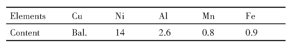
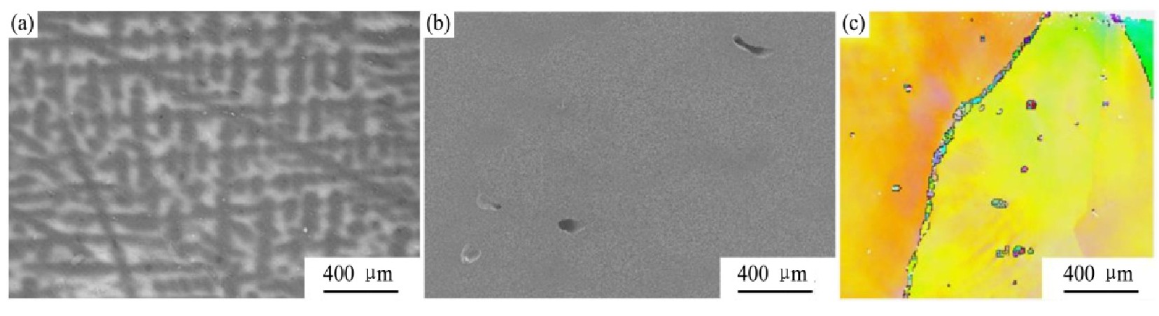
Cu Ni14Al3�Ͻ��������������ϲ������أ������Ͻ���220 mm��Բ���������ӹ�Ϊ��200 mm�Ͻ��������������ۿɼ�ȱ�ݣ��Խ���ȡ�����й۲죬��ͼ1��ʾ��ͼ1(a��Ϊȡ��ʾ��ͼ����ͷΪ���̷���ͼ1(b,c��Ϊͬһ���洦�Ľ�����֯��ͼ1(b��λ�ڽ�о����ͼ1(c��λ����Բ�࣬��о���������Բ������С����ȴ�ٶ�����֦����֯���Ӵִ�һ��֦������ɴ�10 mm���ϣ�ͼ1(d,e��Ϊͬһ��ֱλ�ö��˺͵˵Ķ��ε���ͼ��������̵Ķ�������ڵ˹����С����֦�����Ӵִ�����֦������ڴ��������ɣ�ͼ1(f,g����F��G��������ɨ������ʾ��֦����Ni,Al�ֲ��϶࣬��֦������٣�Ni,Al��ƫ���ȷֱ�Ϊ0.3,0.4��ƫ�������أ�֦���ɡ�֦�����ƽ��Ӳ�ȷֱ�ΪHV242.5,HV 210.8�����13.1%�����ܲ����ȡ�
��ԪCu-Ni�Ͻ���ͼ
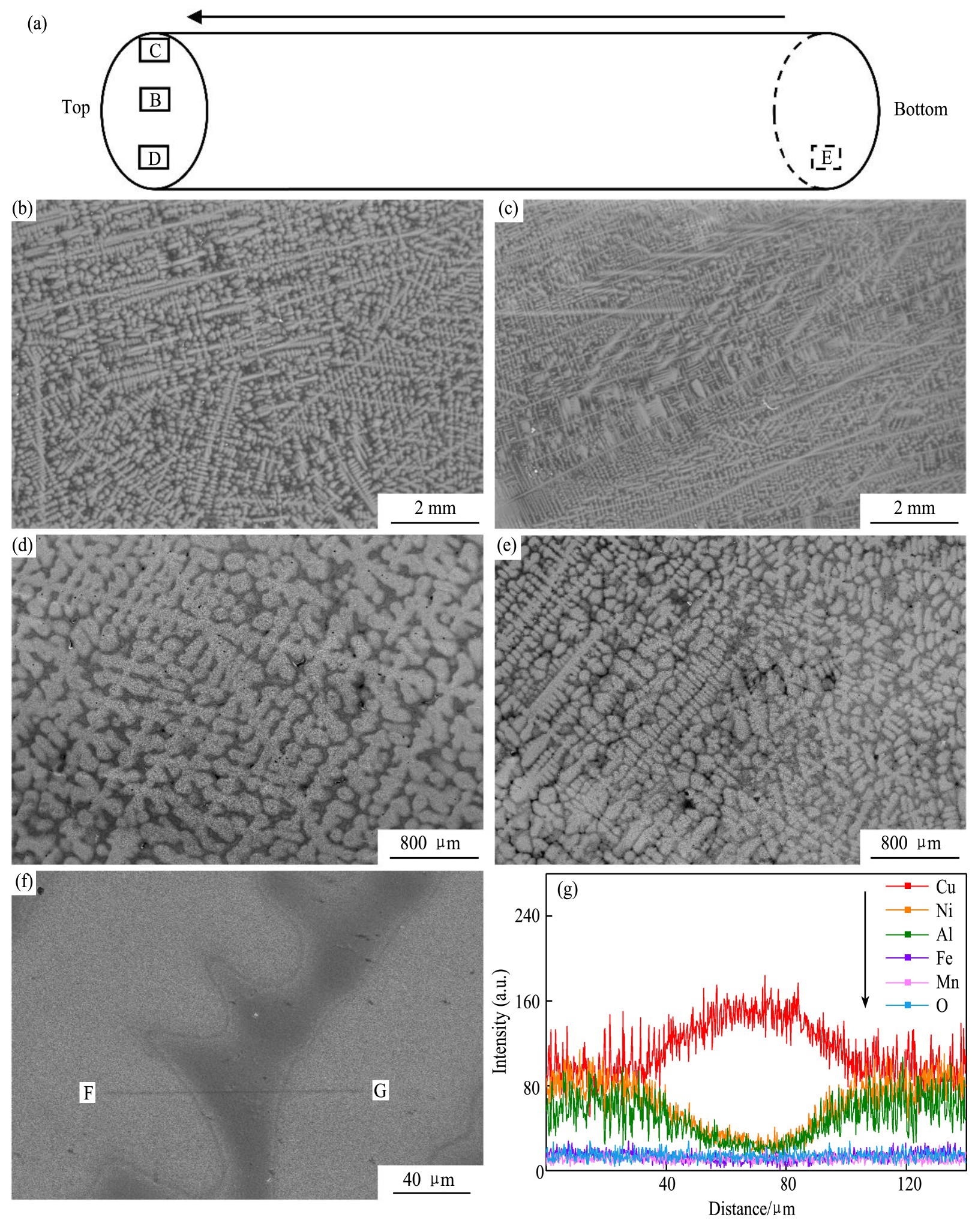
���߷ֱ�ɨ��羵�������۲쵽�Ͻ��д��ڴ����ڶ��࣬��ͼ2��ʾ������2(a��c��Ϊ�ڶ����֦�������ı仯��֦���ɱ�Ե�Ķ��ε���ͼ�ߴ��200 nm�仯��20 nm���ң���ò�������α仯�����ֽӽ����Σ�֦���䴦�ڶ��ຬ���Լ��ߴ綼������С����ͼ2(d����ʾ���پ���羵���������������������ͼ2(e����ʾ���ڶ��װ߽������侧����ǡ��Ni3Al�ľ������������������ͼ2(f����ʾ���ɣ�100������õ��İ������������طֱ��Ni3Al�����࣬��ͼ2(g����ʾ���������������L12������ṹ������������Cu����ľ���ṹ���ƣ���������-����ȡ���ϵ��{100}Cu//{100}Ni3Al,<010>Cu//<010>Ni3Al��ʹ�Ͻ����ѧ���ܵõ��˺ܴ����ߡ�
���ǰ���������ɨ�������Լ�Cu-Ni-Al��Ԫ�Ͻ���800���700���µĵ��½�����ͼ
ͼ1 ��̬Cu Ni14Al3�Ͻ������֯���ɷֲַ�
Fig.1 Microstructure and composition distribution of as-cast Cu Ni14Al3 alloy
(a)Sampling diagram;(b)Near core(Point B);(c)Round side(Point C);(d)Top(Point D);(e)Bottom(Point E);(f,g)EDS result
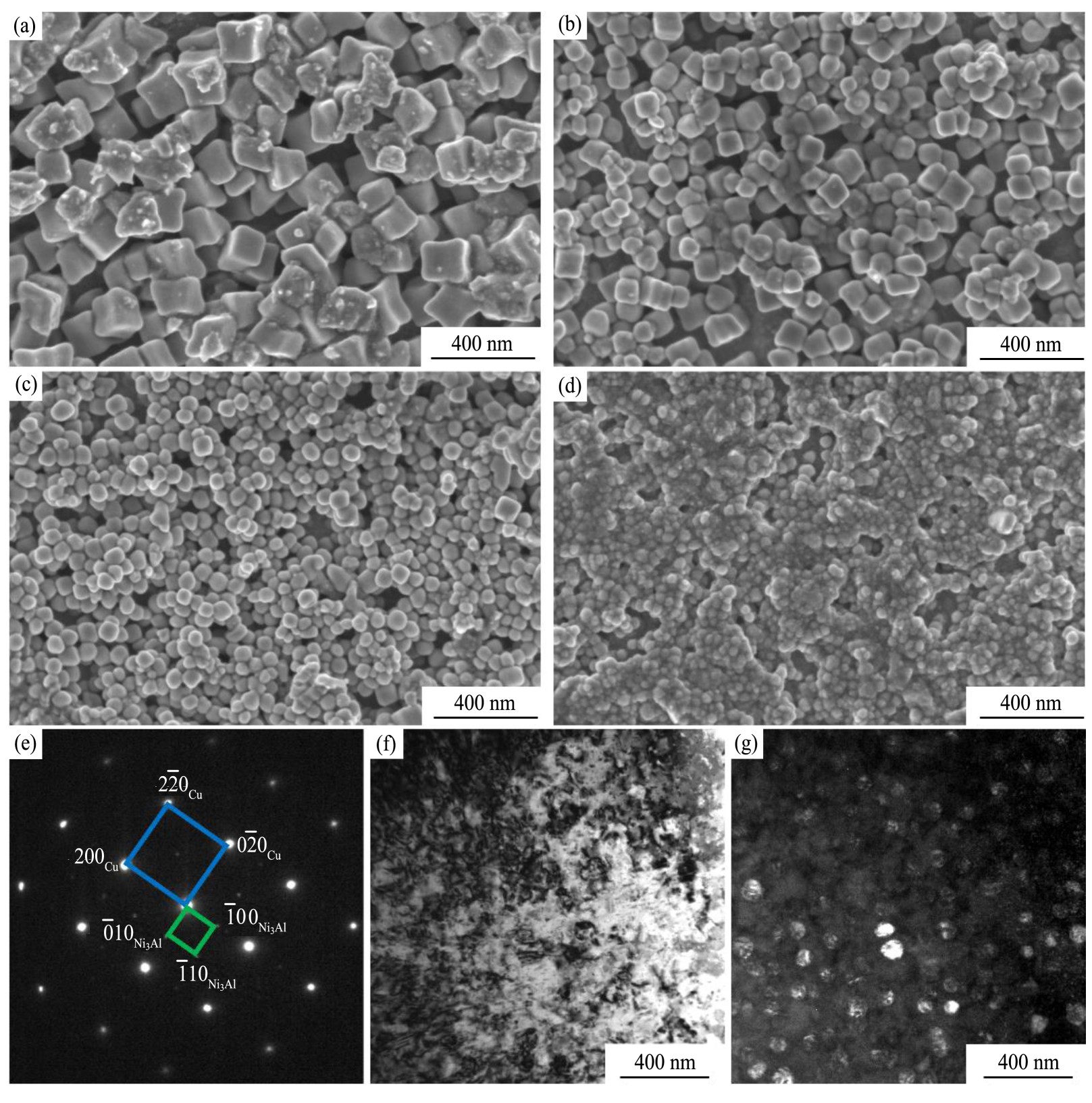
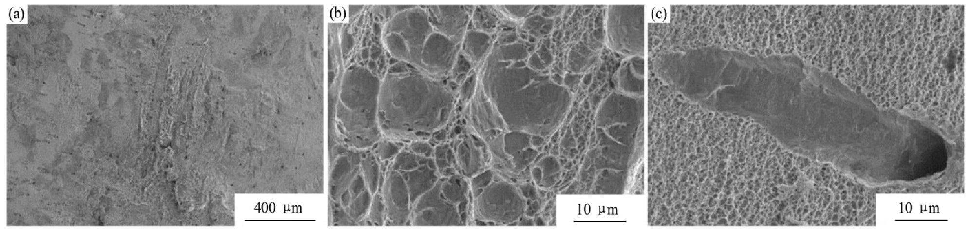
����̬Cu Ni14Al3�Ͻ�������������ܲ��ԣ�������Ͽ���ò��ͼ3��ʾ���Ͽڴ������Եľ������Ͽ�����ò����ƽ���ӽ�45�㱭״���ѣ���ɫ��dz�ػ�ɫ������ò���������״���������ѽ���ҵײ��еڶ�����������ֳ��Ϻõ����ԣ�����ѷ�ʽΪ���͵����Զ��ѡ��Ͽ��滹�۲쵽��������������ǰ��������ϣ������Ʋ����Щ���������ӦΪ�����ɣ��������������±��Ρ�Ӧ�����У�������յĶ��ѡ�
2.2 ��̬Cu Ni14Al3�Ͻ�
2.2.1 ����̬Cu Ni14Al3�Ͻ�
ͼ2 ��̬Cu Ni14Al3�Ͻ��������
Fig.2 Precipitated phases of as-cast Cu Ni14Al3 alloy
(a��d)Secondary electron images;(e)Diffraction pattern;(f)Bright field image;(g)Dark field image
�������һ�������Ŀ������Ͻ������֯��ͼ4(a,b����ʾ����Ȼ���ڴִ����֦���Լ��������ε�������������̬ȱ���Ŵ����˿���̬��δ���Ը��ơ���ͨ������۲첻������ؿ������磬���ڵ��ӱ�ɢ������ģʽ�£����Թ۲쵽���紦�ֲ��Ŵ���ϸС�����������ಿ����Ȼ������ԭʼ������Cu��Ni�IJ���ܽϵͣ�Cu Ni14Al3�Ͻ��������з�����̬�ٽᾧ���ٽᾧ��Ҫ�ھ��紦�κˣ���ԭʼ�����ִ��������������ޣ���˶�̬�ٽᾧ����ȫ���γ���ͼ4(c����ʾ�Ļ쾧��֯��
2.2.2 ����̬Cu Ni14Al3�Ͻ�
ͼ5��ʾΪ����ʱֱ�ӿ��Ѽ�������֯������ͼ5(a��ΪԶ�����ƴ��Ľ�����֯������ڿ���̬������̬�ɹ۲쵽�����ٽᾧ�������ٽᾧ����ϸС��ֻ���ڸ����������ԭʼ������֯�ִ��ټ��ϼ����¶ȡ�������������������Ȳ���ȣ�����ٽᾧ����ȫ�����ֻ쾧��֯�������Ƹ����ٽᾧ�������٣�������������ϸС������ִ������紦��ͼ5(b����ʾ��ͼ5(c��Ϊ���Ƽ�˴��Ķ��ε���ͼ�ɹ۲쵽���紦�Դ���������˵�������ɾ��ڶ������칤�����δ��ȫ���������ھ��紦���ڳɷ�ƫ�����������ټӶ�̬�ٽᾧ�γɵ�ϸС������ԭʼ�ִ����ı���������һ�£�����������ʹ�£���Щ���ع�ͬ���õ��������յĿ��ѡ�
2.2.3 �뻷̬Cu Ni14Al3�Ͻ�
ͼ6��ʾΪ�뻷̬Cu Ni14Al3�Ͻ������Ͽ���ò���������̬�Ͽ���ò�������뻷̬�ĶϿ������Եľ������Ͽ�����òƽֱ����ɫ�����ӽ��Ͻ�����ɫ������ò�����Գ�����״����ͬ���Dz������ѽ�dz���ҽϴ����������½������洦��Ȼ�ɹ۲쵽������������������Լ��١��ߴ���Ա�С��˵������ȱ���ھ������һ������ӹ������Ҳδ����ȫ��������õ��˺ܴ�ĸ��ƣ�������������������Σ�������ܱ��ֳ�����
ͼ3 ��̬Cu Ni14Al3�Ͻ�����Ͽ���ò
Fig.3 Tensile fracture morphology of as-cast Cu Ni14Al3 alloy
(a)Low magnification;(b)Dimples;(c)Cavity
ͼ4 ����̬Cu Ni14Al3�Ͻ������֯
Fig.4 Microstructure of Cu Ni14Al3 alloy in ingot formation state
(a)OM image;(b)SEM image;(c)EBSD image
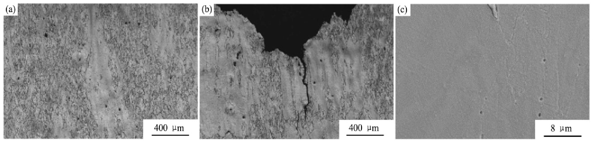
ͼ5 ����̬Cu Ni14Al3�Ͻ������֯
Fig.5 Microstructure of Cu Ni14Al3 alloy in broaching state
(a)Far from cracks;(b,c)Near cracks
ͼ6 �뻷̬Cu Ni14Al3�Ͻ�����Ͽ���ò
Fig.6 Tensile fracture morphology of Cu Ni14Al3 alloy in rolling ring state
(a)Low magnification;(b)Dimples;(c)Cavity
2.3 �˻�̬Cu Ni14Al3�Ͻ�
�˻�̬�����յij�Ʒ��������2 g Fe(NO3)3+50 ml C2H5OH�ĸ�ʴ��dz��ʴ���õ���ͼ7(a����ʾ��Ť���Ĵִ���֦������̬��֦��ƫ��ȱ���ھ���һϵ�еļӹ����պ�õ��˸��Ƶ�δ��ȫ������������ȱ�ݾ����Ŵ��ԡ�����50 ml HNO3+50ml H2O�ĸ�ʴ����ʴ���õ���ͼ7(b����ʾ��ϸС�����������ǰ���������Ľ��࣬�쾧����õ��˺ܴ�ĸ��ƣ��������м�����������ڣ����������̬���ٽᾧ����������������Ϊ�ڳ����ĸ��¶�������У���һ�����պ��ٽᾧ����ȫ���ٴζ���ʱ���ٽᾧ�����κˣ�������ٽᾧ�κ˵ľ�����ʼ����ͬʱ�����������Եõ����ǻ쾧��֯��
��Ʒ����������̽�˺���̽�ˣ������������Ƶ�ȱ�ݣ�����֯��ͼ8��ʾ��ͼ8(a,b��Ϊ����ȱ�ݣ�ͼ8(c,d��Ϊ������ȱ�ݣ�ȱ�ݸ����쾧�����û��ȱ�ݴ����أ����д������ٽᾧ����ȫ�����µı������ľ�����Ҳ���ٽᾧ��������ľ�����ͼ8(e��Ϊ�����ڲ��ĸ߱�ɨ��ͼ�ɹ۲쵽������״�ĵڶ��࣬���þ۽���������FIB������������彻�紦������������羵�����������ͼ8(f,g����ʾ�����д�ͼ8(f�����Կ�������������彻�紦���ڴ�����״�ڶ��࣬���������˵ڶ��࣬����ͼ8(g���иô��Ͻ���ҪԪ�ص����ף�EDS��������������Ի���ȷ������״�ڶ���ΪAl2O3��
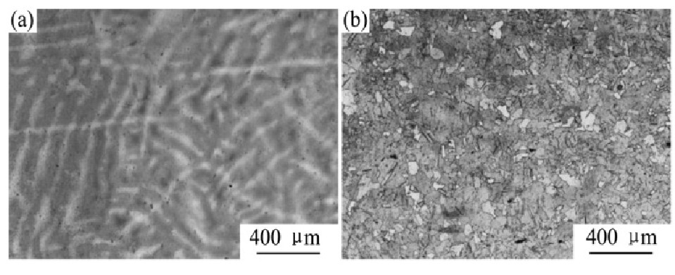
ͼ7 �˻�̬Cu Ni14Al3�Ͻ�����֯
Fig.7 Microstructure of as-annealed Cu Ni14Al3 Alloy
(a)Etched mildly;(b)Etched deeply
ԭʼ�����ִ�����������Ҳ�����أ��������ʱ�����������µĹ�ͬ�����£����������ɵõ����ϣ��������µij����ۼ���˺�ѡ��ߴ��С���������ױ��ۼ����������䣬������ͼ8(b����ʾ�Ŀ����ߴ�ϴ�����ɴ�Ӧ���������أ������ѣ��������۲쵽������ȱ�ݴ��ܻ��������ڽڵ�Ŀ����ڣ������ڿ��Ѻ�ƫ���ľ������۵�;��п��ܱ������������ֲ����գ��ڵ����־��������Ʊ�����������������Al2O3�����ͼ8(d����ʾ��
�����졢ȥӦ���˻���ڸ��º�ѹ���ȹ�ͬ�����£�������Ni3Al�ijߴ��С����ɨ��羵�²��������۲쵽������羵�����ɹ۲쵽��������״���ֽӽ������Σ���ͼ9��ʾ��ͼ9(a��Ϊ����ߺ�������������Ni3Al��Ͻ��Դ��������Ƶľ���ṹ���µ�ȡ���ϵΪ��{110}Cu//{110}Ni3Al,<1-21>Cu//<1-21>Ni3Al��ͼ9(b��Ϊ�ɣ�101������õ��İ�����ͼ9(c��Ϊ�Ͻ�����ҪԪ�ص���������������������ع۲쵽�ֲ���Ծ��ȵ������࣬�ߴ���20��50 nm���ԺϽ����˸��õ�ǿ��Ч����
2.4 �������ܶԱ�
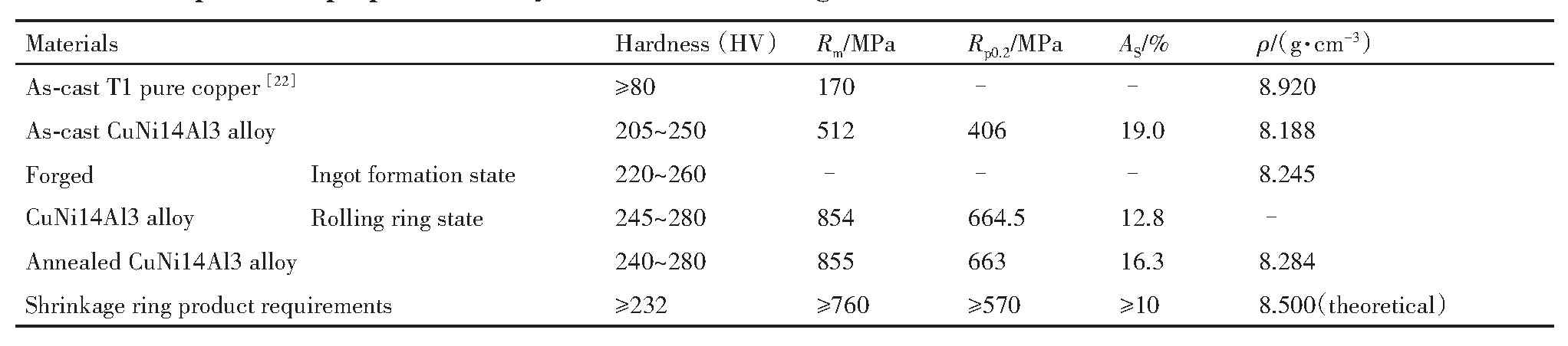
��2Ϊ���ֹ���״̬�£��Ͻ�Ӳ�ȡ����������Լ��ܶȣ��ѣ��ĶԱȣ�����RmΪ����ǿ�ȣ�Rp0.2Ϊ����ǿ�ȣ�AsΪ�����ʣ�����ڴ�ͭ���Ͻ�Ӳ�ȵõ��˴����ߣ���̬�Ͻ�Ӳ�Ⱦͽӽ���ƷҪ������������Ni3Al���˹ؼ����ã�����������ӹ��������������ϸС�������ɷ�ƫ���������ɵõ�Щ�����ƣ��Լ��ڶ���ֲ�����ò�ı仯��ʹ���������ܵõ��˺ܴ����ߣ��úϽ�������ܶȴ�ԼΪ8.5 g��cm-3
2.5 ���ոĽ���ʩ
Cu Ni14Al3�Ͻ���������һϵ�й�����ȱ�ݵ��γɣ�����������̬ȱ�ݣ���Դ���ںϽ���������ԣ���������ʱ�䳤����ͬ��Ԫ����˳��ͬ�����������ȣ�ʹ��֦���ִ���ƫ�������������ء���ˣ���ϴ��ģ��ҵ�����ص㣬�ӸúϽ���������֣���������ȱ�ݣ�������¸Ľ���ʩ��
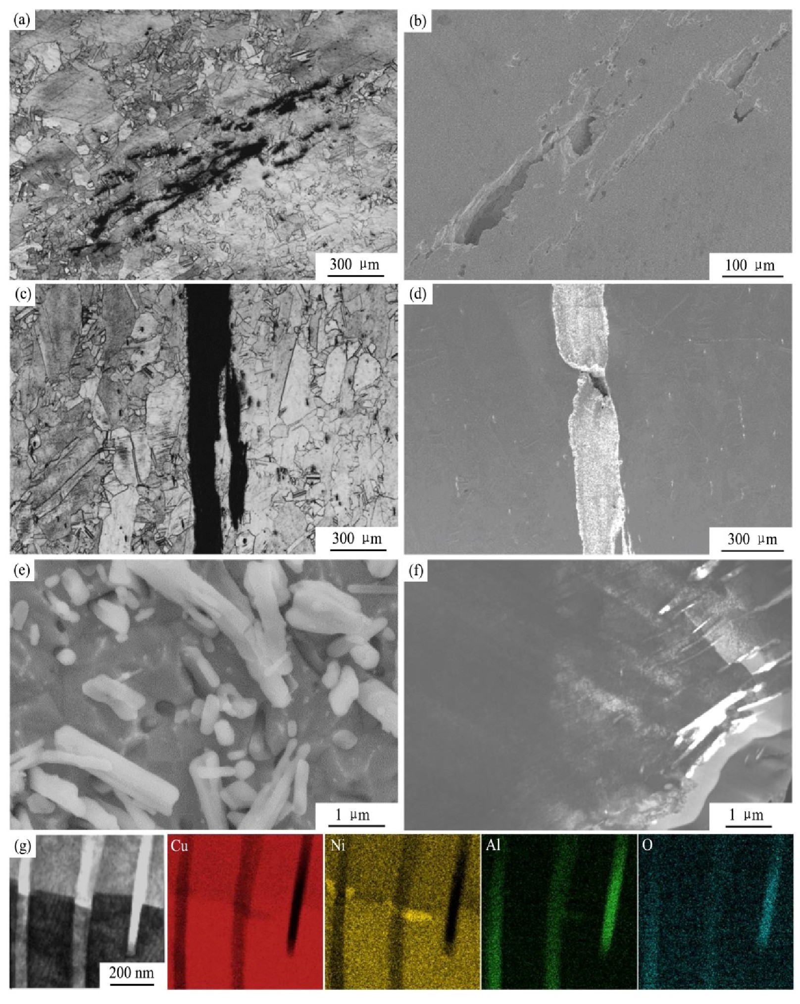
ͼ8 �˻�̬Cu Ni14Al3�Ͻ�ȱ�ݴ�����֯��EDS����
Fig.8 Microstructure of defects in annealed Cu Ni14Al3 alloy
(a,b)Micro-cavities;(c,d)Cracks;(e��g)Internal cracks and EDS results
(1���Ľ��Ͻ�ɷ�
(2���Ż���ע����
(3�����Ӿ��Ȼ��˻���
3 ����
ͨ���Աȷ���Cu Ni14Al3�Ͻ�������ÿ�����պ������֯�����ܣ��ó����½��ۣ�
1.�úϽ������������ֵĹ�����ȱ�ݿɹ���Ϊ����4�ࣺ��1����������ҪΪ�����ɣ���2���ɷ�ƫ������ҪΪ֦��ƫ������3���쾧��֯����4�����ơ�ǰ����ȱ������������������γɣ������Ŵ����˺����ӹ��У�δ�ܵõ���ȫ������������ȱ�ݣ��ڶ��칤�����γɣ������ش���������ʱֱ�ӿ��ѡ�
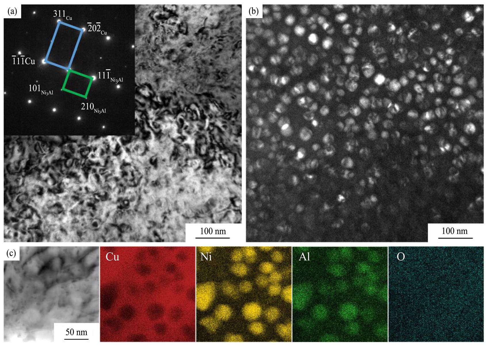
ͼ9 �˻�̬Cu Ni14Al3�Ͻ�������Ni3Al����ò
Fig.9 Microstructure of Ni3Al precipitated phase of annealed Cu Ni14Al3 alloy
(a)Diffraction pattern and bright field image;(b)Dark field image;(c)EDS results
��2 ��ͬ����״̬�ĺϽ����ܶԱ� ����ԭͼ
Table 2 Comparison of properties of alloys in different technological states
2.�úϽ��������Ķ��칤��ȱ��Ϊ�����µ�����ȱ���ݱ������������ȱ�ݵ��γɹ����ںϽ���������ԣ���������ʱ�䡢����˳�����������ȣ���Ҫ���ٻ��������Ϲ�����ȱ�ݣ�����������֣��ϸ��������Ʒ�ʡ�
�����
