
J. Cent. South Univ. Technol. (2011) 18: 731-738
DOI: 10.1007/s11771-011-0755-x![]()
Characteristics of radiation and convection heat transfer in indirect near-infrared-ray heating chamber
CHOI Hoon-ki, YOO Geun-jong, KIM Churl-hwan
School of Mechatronics, Changwon National University, Changwon 641-773, Korea
? Central South University Press and Springer-Verlag Berlin Heidelberg 2011
Abstract:
Numerical study was performed to evaluate the characteristics of combined heat transfer of radiation, conduction and convection in indirect near infrared ray (NIR) heating chamber. The effects of important design parameters such as the shape of heat absorbing cylinder and heat releasing fin on the pressure drop and heat transfer coefficient were analyzed with different Reynolds numbers. The Reynolds numbers were varied from 103 to 3��106, which was defined based on the hydraulic diameter of the heat absorbing cylinder. Analyses were performed to obtain the inner and outer flow and the temperature distributions in the heat absorbing cylinder and the rates of radiation heat transfer and convection heat transfer. As the Reynolds number increases, the convection heat transfer rate is increased while the radiation heat transfer rate is decreased. The average convection heat transfer rate follows a power rule of the Reynolds number. Addition of three-dimensional heat releasing fin to the outside of the heat absorbing cylinder enhances the convection heat transfer.
Key words:
1 Introduction
Heater fan was classified differently by types of heat source and blowing. The heater fan using direct combustion was widely found; however, it had shortcomings of air pollution and high cost. The electric resistance type could provide remedies of these shortcomings, yet yielded low efficiency at high heating capacity. As an alternative, indirect near-infrared-ray (NIR) heater fan (NIR heater) was developed and this required detailed study on the heat transfer mechanism.
The NIR heater provided energy to air for heating or drying purpose. Direct heating by radiation itself from NIR (0.7-1.4 ��m) lamp had very low heat transfer efficiency, thus heat absorbing cylinder (HAC) was added to enhance the heat transfer effect in the NIR heater, as shown in Fig.1. The HAC was made of high conductive aluminum and its inside was coated with black special material to increase the radiation heat transfer. Energy emitted from the central NIR lamp was delivered and absorbed to the HAC. This energy was delivered through the cylinder wall by conduction and to outside air by the convection in sequence.
Study on combined heat transfer of radiation and convection heat transfer was reported steadily. ECHIGO et al [1], MEHTA and KUMAR [2], YANG and EBADIAN [3], ZHENG et al [4] and SCHULER and CAMPO [5] performed numerical analyses for the combined heat transfer in pipe system. For varying Reynolds numbers, the distribution of the velocity and temperature and heat transfer coefficient were obtained in their studies. AL-AMRI FRAHAD and EI- SHAARAWI MAGED [6] and CHERIF et al [7] analyzed the combined convection and radiation heat transfer in the channel. Total heat flux and Nusselt number were obtained and systematic comparison for experimental and numerical results was given. BALAJI et al [8] carried out asymptotic computational fluid dynamics study for two dimensional lid driven cavity with different heating conditions. In their study, correlation of convective Nusselt number and radiative Nusselt number was presented with the variation of important parameters. MAHAPATRA et al [9-10] proposed some aspects of mathematical modeling for coupled conduction and radiation heat transfer in two- dimensional square enclosure with absorbing, emitting and isotropic scattering gray medium. Iso-thermal distributions were presented along the surface emissivity and optical thickness. And the effect of influencing parameters on fluid flow and heat transfer was identified. It was demonstrated that the natural and forced convection heat transfer in a uniformly heated circular cylinder is important. MOHAMMED and SALMAN [11] carried out combined heat transfer by numerical analysis for a constantly heated circular pipe. SOARES et al [12] performed forced convection heat transfer using numerical method in crossflow over circular cylinder. In their analysis, Nusselt number was presented with the Reynolds number.
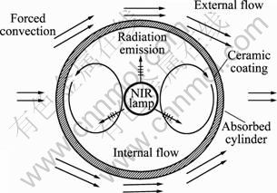
Fig.1 Mechanism of combined heat transfer in unit cylinder
The heater fan performance could be determined by the size of pressure drop and heat transfer coefficient. Regarding the effects of these parameters, a wide range of study results could be found for cylindrical pipe and tube bank with heat releasing fin (HRF). GIANOLIO and CUTI [13] and NIR [14] studied the forced convection in staggered finned tube banks and suggested the relationship of friction factor and the heat transfer coefficient in terms of Reynolds number. However, not many research results were found for the heat transfer characteristics of the NIR heater.
In this work, the characteristics of complex heat transfer mechanism were analyzed in both regions of inside and outside of the unit HAC. To obtain proper shape of the HAC, two-dimensional circular and elliptic types were analyzed. Three-dimensional analysis was further performed to assess the effect of HRF on the outside convection heat transfer.
2 Numerical analysis
2.1 Computational domain
As presented in Fig.1 and Table 1, the NIR heater had combined the heat transfer modes. The NIR heater consisted of arrays of individual HAC and fan, as shown in Fig.2.
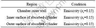
Table 1 Characteristics of heat transfer in analysis domain
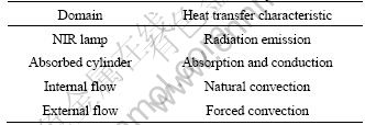
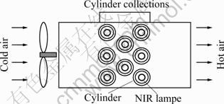
Fig.2 Schematic diagram of absorbing cylinders and heating chamber
Detailed analysis was required to obtain complete characteristics of heat transfer mechanism for the entire NIR heater; however, it was limited due to the huge computational capacity. The computational domain included the HAC and its near region since this region contained all the basic heat transfer mechanism of the NIR heater. In addition to this component and region, inlet and outlet were added to have final domain to simulate absorbing characteristics of emitted heat from the surface of the HAC in the NIR heater, as shown in Fig.3.
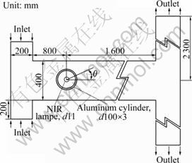
Fig.3 Calculation domain for unit cylinder in heating chamber
The shape of the HAC was an important parameter to determine the performance of the NIR heater. Its shape was designed to have high radiation heat transfer from the lamp. Consideration was also needed to have high convection heat transfer and low air flow resistance. Two different types of circular and elliptic cylinders shown in Fig.4 were analyzed to compare the characteristics of heat transfer and flow resistance. To have the same heat absorbing area, peripheral length, SC, as presented in Eq.(1) was kept the same for two different types of cylinders:
![]() (1)
(1)
where D=D0-2t, a=a0-2t, and b=b0-2t.
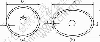
Fig.4 Configuration of two-dimensional absorbed cylinders: (a) Circular cylinder; (b) Ellipse
The HRF was added to outside of the HAC to obtain the enhanced heat transfer and three-dimensional analysis was performed with different Reynolds numbers to have better understanding for the role of the HRF. Figure 5 shows the shape of HAC with and without HRF.
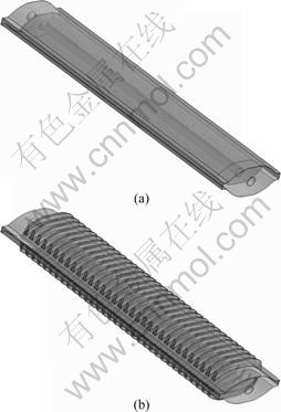
Fig.5 Configuration of three-dimensional absorbed cylinders: (a) Without fin; (b) With fin
2.2 Governing equations
The governing equations to express combined heat transfer modes could be presented as follows.
Continuity equation:
![]() (2)
(2)
Momentum equation:
![]()
![]() (3)
(3)
Energy equation:
![]() (4)
(4)
Turbulent transport equations (standard k-�� model):
![]() (5)
(5)
![]() (6)
(6)
where ![]() and C��=0.09, ��k=1.0, ����=1.3, C��1=1.44, C��2=1.92.
and C��=0.09, ��k=1.0, ����=1.3, C��1=1.44, C��2=1.92.
Conduction heat transfer equation:
![]() (7)
(7)
Radiation heat transfer equation:
![]()
![]() (8)
(8)
where Iv represents the radiation intensity which varies along the space vector. Ib is the radiation intensity for black body and is expressed with Monte Carlo model [15] which has high accuracy even for transparent fluids such as air.
Various boundary conditions required by the above governing equations are summarized in Tables 2-4 for velocity, temperature and radiation, respectively.
Table 2 Velocity boundary conditions
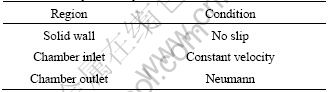
Table 3 Temperature boundary conditions
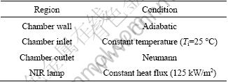
Table 4 Radiation boundary conditions
2.3 Numerical scheme
The entire computational domain included the internal flow region between the lamp surface and inner surface of the HAC, solid surface of the HAC, external flow region covering outer surface of the HAC and air. Numerical analyses were performed in two steps. The first one was two-dimensional analysis to determine the shape of HAC with around 130 000 grid points and the second one was three-dimensional analysis to find the effect of HRF with around 2 040 000 grid points.
Detailed numerical analysis was performed using CFX v12 [16]. Hybrid scheme based on the 1st order upwind and central schemes was selected to have stable computation for convection term and this was integrated with SIMPLE scheme [17].
3 Results and discussion
3.1 Determination of HAC shape
1) Flow and temperature distributions in region outside of HAC
As reported variously by many researchers such as CHANG [18], ANDERSON et al [19] and WHITE [20], flow around cylinder has boundary layer developed in front region (region around ��=180��) and this boundary layer is separated by adverse pressure gradient in rear region (region around ��=0��). Figure 6 shows the streamline distributions around the circular and elliptic cylinders for the turbulent flow of Re=105 and the flow separation can be seen in the rear region clearly. Meanwhile, the separation region in elliptic cylinder is small compared with that in circular cylinder. This indicates that the pressure drop in flow around elliptic cylinder has rather low value, as shown in Fig.7, in terms of pressure coefficient, Cp=0.5(p-p��)/ ![]() Once the separation occurs, the value of pressure coefficient remains almost the same. Using this characteristic together with Fig.7, the separation point for the elliptic cylinder is found at further downstream compared with that of the circular cylinder and these result in a reduced drag force and a low pressure coefficient to allow high air flow rate. The important design parameters of heater fan are the air flow rate and heat transfer performance. The elliptic cylinder type shows higher flow rate and similar heat transfer performance to the circular cylinder type, and the further detailed study is limited to the elliptic cylinder shape.
Once the separation occurs, the value of pressure coefficient remains almost the same. Using this characteristic together with Fig.7, the separation point for the elliptic cylinder is found at further downstream compared with that of the circular cylinder and these result in a reduced drag force and a low pressure coefficient to allow high air flow rate. The important design parameters of heater fan are the air flow rate and heat transfer performance. The elliptic cylinder type shows higher flow rate and similar heat transfer performance to the circular cylinder type, and the further detailed study is limited to the elliptic cylinder shape.
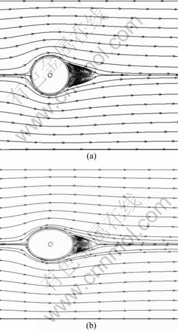
Fig.6 Contours of streamline around cylinder (Re=105): (a) Circular cylinder; (b) Ellipse
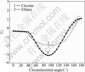
Fig.7 Pressure distribution around cylinder
The temperature distribution around the elliptic cylinder is presented in Fig.8. The thermal boundary layer is interrupted by the flow boundary layer separation to have small temperature gradient. Due to this small temperature gradient, the convection heat transfer rate is also reduced in this region.
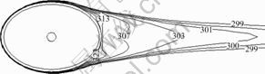
Fig.8 Contours of temperature (K) around cylinder (Re=105)
2) Flow and temperature distributions in region inside HAC
Fig.9 shows the flow and temperature distributions for the internal region. From the surface of lamp, energy is emitted with constant heat flux and the lamp surface temperature is remained over 1 400 K. Emitted radiation heat is absorbed to the inner surface of the HAC. Thus, the temperature of the HAC inner surface is raised but remains lower than the lamp surface temperature. Air inside the HAC is completely enclosed without inlet or outlet; therefore, natural convection is the only way to deliver energy. Around the high temperature lamp surface, air density is decreased to obtain strong upward buoyant flow. The temperature of the inner surface of the HAC has lower value than that of the lamp and air and this leads to the downward buoyant flow. As a result, a pair of flow cell is formed. The upward flow around the lamp raises the air temperature in the region at the top of the lamp and the downward flow along the HAC creates the low air temperature region at the bottom of the lamp.
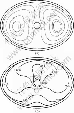
Fig.9 Distributions of iso-contours in cylinder (Re=105): (a) Streamline; (b) Temperature (K)
3) Temperature distribution in HAC surface
Figure 10 shows the temperature distribution in the HAC surface. The HAC surface has combined effect of radiation heat transfer from the lamp, natural convection heat transfer from the inner surface and forced convection heat transfer to outside air. Due to the different velocities around the HAC, the forced convection differs because of the low temperature distribution in the front region of cylinder and rather high temperature distribution in the rear region. The emitted radiation heat from the lamp itself can provide even temperature distribution in the inner surface of the HAC; however, the natural convection inside the cylinder results in the asymmetric distribution to have low temperature in the lower part of the HAC.
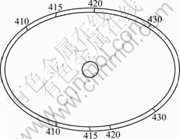
Fig.10 Contours of temperature on cylinder (Re=105)
4) Characteristics of combined heat transfer
The characteristics of combined heat transfer are determined by the radiation from the lamp surface, natural convection, surface conduction and forced convection together with cylinder surface radiation.
Among these, the forced convection is affected by the air flow rate directly, thus is analyzed with different flow velocities. The forced convection heat transfer rate along the outside surface of the HAC is presented in Fig.11 for different Re values to see the effect of flow velocity. The heat transfer rate has high level due to the accelerated flow velocity in the front region, while has low level in the rear region since the flow and thermal boundary layers are interrupted by the separation. For flows with low Re, the heat transfer rate remains almost constant because it has no or very low separation effect. However, the separation region is increased with increasing Re and the heat transfer rate is decreased significantly near the top and bottom regions. At the front of the HAC (��=180��), the stagnation point is found and this makes the heat transfer rate low due to the low flow velocity. This decreasing trend is further significant as the Re value increases. As shown in Fig.11, rapidly decreased heat transfer rate can be found in the rear region of the HAC and this point can be reasonably assumed as the separation point.
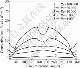
Fig.11 Plots of forced convection heat flux along outside surface of HAC
As mentioned earlier, the radiation heat transfer is accompanied by the convection at the outside surface of the HAC and depends on the surface temperature which is affected directly by the flow velocity. Figure 12 shows the radiation heat transfer rate along the outside surface of the HAC for different Re values to see the effect of the flow velocity. The radiation heat transfer has only small difference between the front and rear regions of the HAC due to the small temperature difference in the cylinder surface as shown in Fig.10. This indicates that the radiation heat transfer mainly depends on the surface temperature and has similar value along the surface at a certain Re value. However, the radiation heat transfer rate is decreased as Re increases since high Re yields low surface temperature.
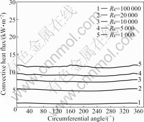
Fig.12 Plots of radiative heat flux along outside surface of HAC
The total heat transfer from the surface of HAC is obtained with the sum of radiation and convection as explained above and its total level remains the same. Figure 13 presents the comparisons of two different heat transfer modes with varying Re. Increasing Re indicates increased flow velocity and high velocity and temperature gradients consequently. This, in turn, increases the convection and decreases the radiation heat transfer. Two different types of circular and elliptic HAC do not affect much on the outside heat transfer characteristics.
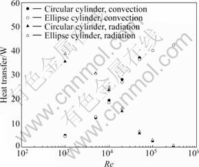
Fig.13 Comparison of convective heat transfer rate and radiative heat transfer rate
Generally, the Nusselt number for cross flow on the cylinder can be presented with Re and Pr following the suggestion of CHURCHILL and BERNSTEIN [21] as
![]() (9)
(9)
Pr can be kept constant for the case with the same fluid. Average heat transfer coefficient can be obtained from Eq.(9) and even further simplified using constant Pr of 0.7 as
![]() (10)
(10)
In this study, Pr, conductivity (k) and diameter of the HAC can be fixed; thus, the average heat transfer is expressed as a function of Re only. In Eq.(10), C is a proportional constant and exponent m is varied with Re. CHURCHILL and BERNSTEIN [21] reported the value of m to be 0.6-0.8 in the range of 4��103��Re��4��105 for the cross flow on the cylinder. Figure 14 presents the two-dimensional analysis results of the average heat transfer rate for the circular and elliptic HAC. From this result, the values of C and m of Eq.(10) are evaluated to be 0.015 6 and 0.779 8, respectively. The value of m is found to be independent of Re and the geometric shape of the HAC. From this, it is known that both types of HAC have similar heat transfer performance; however, the elliptic HAC has better performance to have air flow as explained.
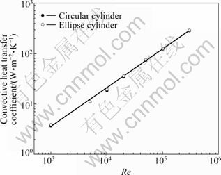
Fig.14 Variation of convection heat transfer coefficient with Reynolds number
3.2 Effect of HRF
To determine the proper shape of the HAC, two- dimensional analysis is applied and its resulting heat transfer characteristics are considered. The real NIR heater, as shown in Fig.15, requires three-dimensional analysis. Since the main purpose of the NIR heater is to raise the air temperature, additional design consideration is needed to increase the convection heat transfer at outside surface. For this purpose, HRF is attached to the outside of the three-dimensional elliptic HAC and the heat transfer analysis is applied. Figure 16 presents the heat transfer analysis results for the case with HRF with different Re value. As Re increases, convective heat transfer coefficient is also increased to have high convection but low radiation. In the limit of very high Re, most heat transfer is done by the convection mode.
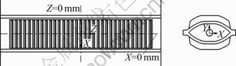
Fig.15 Configuration of three-dimensional absorbed cylinder with heating fin
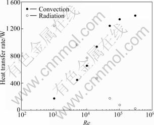
Fig.16 Comparison of convection heat transfer rate and radiative heat transfer rate for case with HRF
Heat transfer around the NIR heater is dominated by the convection. The convection heat transfer can be enhanced by either increasing the heat transfer area such as using HRF or increasing the air velocity. Figure 17 shows the effect of convection heat transfer by varying the air flow velocity with and without HRF. As Re increases, the heat transfer rate is also increased significantly until it reaches the steady limit at very high Re value. The case with HRF yields higher heat transfer rate consistently compared with the case without HRF.
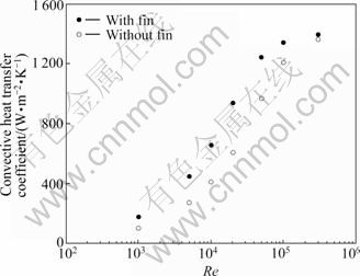
Fig.17 Comparison of convection heat transfer rate with fin and without fin
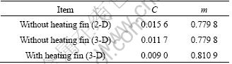
To see further the detailed effect of the geometric configuration, the average convection heat transfer rate from 2-D and 3-D analysis for the case without HRF and 3-D analysis for the case with HRF is presented in Fig.18. Table 5 lists a summary of heat transfer characteristics of each case using the correlation given in Eq.(10). For the case without HRF, the exponent of Re, m, is kept constant but the constant C has small difference to show slight over-prediction in 2-D analysis. The case with HRF yields higher m, indicating high convection heat transfer rate. GIANOLIO and CUTI [13] reported the value of m as 0.68-0.70 for the cross flow on the staggered finned tube bank with HRF, while CHURCHILL and BERNSTEIN [21] reported the value of m as 0.808 in the range of 4��103��Re��4��105 for the cross flow on the single cylinder. Comparing Table 5, the current study is found to have a tendency to follow the pattern of CHURCHILL and BERNSTEIN [21].
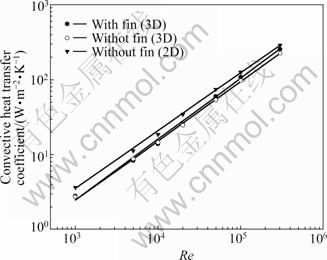
Fig.18 Changes of convective heat transfer coefficients with Reynolds number
Table 5 Values of coefficients C and m
4 Conclusions
1) The elliptic type HAC, compared with the circular type HAC, has similar heat transfer characteristics but low pressure drop.
2) Inside the HAC, the natural convection forms a pair of flow cell but affects little on the outside air temperature.
3) As Re increases, the convection heat transfer is increased and the radiation is decreased at the outside surface of HAC.
4) The average convection heat transfer coefficient at the outside surface of HAC follows the correlation of ![]() and the value of m is increased for the case with HRF.
and the value of m is increased for the case with HRF.
Nomenclature
C, CNu Correlation constant
D Inner diameter of circular cylinder
Gk ![]() generation term of turbulent kinetic energy
generation term of turbulent kinetic energy
g Acceleration of gravity
![]() Average heat transfer coefficient
Average heat transfer coefficient
Ib Blackbody emission intensity
Iv Spectral radiation intensity which depends on position and direction
Ka Absorption coefficient
Ks Scattering coefficient
k Turbulent kinetic energy
k Thermal conductivity
Nu Nusselt number
p Pressure
Pr Plandtl number
Re Reynolds number
r Position vector
s Direction vector
Tl Local absolute temperature
T Temperature
Ui Velocity in i-direction
ui Fluctuating velocity in i-direction
�� Dissipation rate of turbulent kinetic energy
��t Turbulent viscosity
�� Molecular viscosity
v Frequency
�� Density
�� In-scattering phase function
�� Solid angle
References
[1] ECHIGO R, HASEGAWA S, KAMITUTO K. Composite heat transfer in a pipe with thermal radiation of two-dimensional propagation in connection with the temperature rise in flowing medium upstream from heating section [J]. Int J Heat Mass Transfer, 1975, 18(10): 1149-1159.
[2] MEHTA R C, KUMAR P. Numerical analysis of a tube with heat generation, thermal radiation, convection and axial conduction [J]. International Journal Heat Mass Transfer, 1985, 28(11): 2169-2171.
[3] YANG G, EBDIAN M A. Thermal radiation and laminar forced convection in the entrance region of a pipe with axial conduction and radiation [J]. The International Journal of Heat and Fluid Flow, 1991, 12(3): 202-209.
[4] ZHENG B, LIN C X, EBDIAN M A. Combined turbulent forced convection and thermal radiation in a curved pipe with uniform wall temperature [J]. Numerical Heat Transfer (Part A): Applications, 2003, 44(2): 149-167.
[5] SCHULER C, CAMPO A. Numerical prediction of turbulent heat transfer in gas pipe flows subject to combined convection and radiation [J]. The International Journal of Heat and Fluid Flow, 1988, 9(3): 308-315.
[6] AL-AMRI FAHAD G, EI-SHAARAWI MAGED A I. Combined forced convection and surface radiation between two parallel plates [J]. The International Journal of Numerical Methods for Heat and Fluid Flow, 2010, 20(2): 218-239.
[7] CHERIF Y, JOULIN A, ZALEWSKI L, LASSUE S. Superficial heat transfer by forced convection and radiation in a horizontal channel [J]. International Journal of Thermal Science, 2009, 48: 1696-1706.
[8] BALAJI C, HOLLING M, HERWI H. Combined laminar mixed convection and surface radiation using asymptotic computational fluid dynamics (ACFD) [J]. Heat and Mass Transfer, 2007, 43(6): 567-577.
[9] MAHAPATRA S K, NANDA P, SARKAR A. Analysis of coupled conduction and radiation heat transfer in presence of participating medium-using a hybrid method [J]. Heat and Mass Transfer, 2005, 41: 890-898.
[10] MAHAPATRA S K, NANDA P, SARKAR A. Interaction of mixed convection in two-sided lid driven differentially heated square enclosure with radiation in presence of participating medium [J]. Heat and Mass Transfer, 2006, 42: 739-757.
[11] MOHAMMED H A, SALMAN Y K. Combined natural and forced convection heat transfer for assisting thermally developing flow in a uniformly heated vertical circular cylinder [J]. International Communications in Heat and Mass Transfer, 2007, 34(4): 474-491.
[12] SOARES A A, FERREIRA J M, CHHABRA R P. Flow and forced convection heat transfer in crossflow of non-Newtonian fluids over a circular cylinder [J]. Industrial & Engineering Chemistry, 2005, 44(15): 5815-5827.
[13] GIANOLIO E, CUTI F. Heat transfer coefficients and pressure drops for air coolers with different numbers of rows under induced and forced draft [J]. Heat Transfer Engineering, 1981, 3(1): 38-48.
[14] NIR A. Heat transfer and friction factor correlations for cross flow over staggered finned tube banks [J]. Heat Transfer Engineering, 1991, 11(1): 44-58.
[15] MICHAEL F M. Radiative heat transfer [M]. Academic Press, 2003.
[16] CFX v12 Solver theory [M]. South Pointe: ANSYS Inc, 2009: 1- 169.
[17] PATANKAR S V. Numerical heat transfer and fluid flow [M]. New York: McGraw-Hill, 1980: 1-78.
[18] CHANG P K. Control of flow separation [M]. New York: McGraw-Hill, 1976: 199-209.
[19] ANDERSON A D, TANNEILL J C, PLETCHER R H. Computational fluid mechanics and heat transfer [M]. 2nd ed. New York: McGraw-Hill, 1997: 479-518.
[20] WHITE F M. Viscous fluid flow [M]. New York: McGraw-Hill, 1991: 190-205.
[21] CHURCHILL S W, BERNSTEIN M A. Correlating equation for forced convection from gases and liquids to a circular cylinder in cross flow [J]. Journal Heat Transfer, 1977, 99: 300-306.
(Edited by YANG Bing)
Foundation item: Work supported by the Second Stage of Brain Korea 21 Projects
Received date: 2010-06-28; Accepted date: 2010-11-30
Corresponding author: CHOI Hoon-ki, Associate professor, PhD; Tel: +82-55-213-3628; E-mail: hkchoi@changwon.ac.kr
[15] MICHAEL F M. Radiative heat transfer [M]. Academic Press, 2003.
[16] CFX v12 Solver theory [M]. South Pointe: ANSYS Inc, 2009: 1- 169.
[17] PATANKAR S V. Numerical heat transfer and fluid flow [M]. New York: McGraw-Hill, 1980: 1-78.
[18] CHANG P K. Control of flow separation [M]. New York: McGraw-Hill, 1976: 199-209.
[20] WHITE F M. Viscous fluid flow [M]. New York: McGraw-Hill, 1991: 190-205.
