
Article ID: 1003-6326(2005)02-0328-04
Preparation and characterization of BaMgAl10O17��Eu phosphor coated with MgF2 by sol-gel process
LI Feng(�� ��), WANG Yu-hua(������)
(Department of Materials Science, Lanzhou University, Lanzhou 730000, China)
Abstract:
In order to prevent BaMgAl10O17��Eu (BAM) phosphor from thermal degradation, MgF2-coatings on the surface of BAM were prepared by a sol-gel process. The coatings were characterized by X-ray photoelectron spectroscopy and scanning electron microscopy. The results indicate that BAM is successfully coated with homogenous, close MgF2 coatings. The photoluminescence and anti-thermal degradation properties of coated BAM were investigated under 254 and 147nm excitations. The optimum anti-thermal degradation properties are obtained at the mass ratio of MgF2 to BAM 0.2% under 254nm excitation and 0.5% under 147nm excitation, respectively. It is considered that trace MgO formed after baked would cause different optimum coating thicknesses under 254 and 147nm excitations.
Key words:
BaMgAl10O17; Eu; thermal degradation; sol-gel process; coating CLC number: O482.31;
Document code: A
1 INTRODUCTION
Recently, because of the requirement of plasma display panels(PDPs) and a possible new generation of Hg-free lamps, much attention has been paid to phosphors for vacuum ultraviolet (VUV) radiation. BaMgAl10O17��Eu (BAM) is widely used in PDP and Hg-free lamp due to its high luminescence efficiency and good chromaticity[1], and also used in other displays and lamps. However, luminance degradation of BAM, consisting of thermal degradation and lifetime degradation, restrains the properties of PDP, especially its lifetime. Thermal degradation occurs when BAM is heated to about 600�� in ambient atmosphere during the manufacturing of PDP. It is generally considered that the luminescent center Eu2+ is oxidized to Eu3+[2]. Lifetime degradation is caused by VUV radiation and ion sputtering during PDP operation, which can be explained by the formation of an amorphous surface layer[2]. Since VUV radiation has a low penetration depth, such an amorphous and non-luminescent surface layer causes a substantial decrease in the brightness. In lamps, the degradation of BAM is mainly caused by thermal treatment during lamp manufacturing.
One of the options to enhance the thermal stability and ion resistance in BAM is the application of a closed particle coating. J��stel et al[3] found that a thin phosphate coating was effective in preventing BAM from thermal degradation. However, the coating reduces the phosphor efficiency due to the absorption of VUV light in the coating layer[4]. Do et al[5] applied sol-gel process to coat BAM with SiO2 or Al2O3, but these coatings also absorb VUV radiation severely. To minimize this effect the coating must not be thicker than 10nm[4]. However, such a thin coating would be easily destroyed during the PDP manufacturing process, and can not stand ion-sputtering. This narrows the choice of coating materials to fluorides because of their wide bandgaps[4].
Hirofumi et al[6] used a precipitation process to coat BAM with metal fluoride in order to protect phosphor from thermal degradation during lamp manufacturing. However, this process results in poor adherence of the coating to the phosphor[7, 8]. Furthermore, CVD (chemical vapor deposition) and PVD (physical vapor deposition) would be good choices[9], but both are highly apparatus-dependent, requiring elaborate instrumentation, careful air flow and temperature monitoring[7]. Thus the cost of the phosphor fabrication process is increased.
MgF2 is a suitable coating material for BAM due to its wide transparency range, 130-7400nm, good toughness[10], and high secondary electron emission coefficient which can improve the pixel brightness[11]. In this paper, MgF2-coated BAM is prepared by sol-gel process and its luminescent properties and thermal stability are investigated under 254nm and 147nm excitation.
2 EXPERIMENTAL
The starting materials were TFA (CF3COOH, CP), Mg(CH3COO)2��4H2O (AR) and iso-C3H7OH (AR). BAM was co-prepared by Tohoku University of Japan and the authors.
0.005mol Mg(CH3COO)2��4H2O was dissolved in 15mL isopropanol with the addition of 2mL TFA and 2mL distilled water. The solution was stirred for 2h and then diluted to 300mL with isopropanol. BAM phosphor particles were added to the solution at the mass ratio MgF2 to BAM=0.1%-1.0% and stirred for 15min. Then the solution mixed with BAM was dried at 80�� for 24h so that dry gel containing BAM phosphor was obtained . After calcined at 300�� for 15min, BAM particles coated with MgF2 were produced.
X-ray photoelectron spectroscopy (XPS) was carried out on a MICROLAB VG 210 instrument for surface components analysis. Surface morphology was observed with a scanning electron microscope(SEM, Model JSM-5600LV). Emission spectra under 254nm excitation were measured by a Shimadzu RF-450 fluorescence spectrophotometer. Under 147nm excitation were recorded on an ARC Model VM-502 type vacuum monochromatic. All the spectra were recorded at room temperature.
3 RESULTS AND DISCUSSION
The coating process of BAM was carried out according to the reactions[12, 13]:
Mg(CH3COO)2+2CF3COOH=
Mg(CF3COO)2+2CH3COOH
Mg(CF3COO)2��
MgF2+(CF3CO)2O��+CO��+ CO2��
The XPS analysis of a series of samples shows that BAM phosphor particles are coated with MgF2 via sol-gel process. As a example, Table 1 lists the element components of uncoated and coated BAM phosphor with 0.2% MgF2(mass fraction). Comparing the raw BAM and the coated BAM, in the latter case the concentrations of barium, oxygen and aluminum decreases whereas the occurrence of fluorine and an increased magnesium was observed. Table 2 shows Mg2p and F1s checked in the coated sample. It indicates that they are closed to that of MgF2 standard, in which Mg2p is 50.95eV and F1s is 685.75eV. These results indicate that the surface of BAM phosphor has been efficiently covered with MgF2.
Table 1 XPS analysis of element components of uncoated and coated BAM phosphor surface (mole fraction, %)
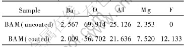
Table 2 Binding energies of elements of uncoated and coated BAM phosphor surface(eV)
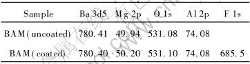
Fig.1(a) shows the SEM micrograph of BAM phosphor particles coated with 0.2% MgF2. No clear difference exists between the coated surface and the uncoated one. However a close look shown that there are burrs on the edges of the coated BAM and the uncoated��s are sharp. So the burrs could grow from the film coated on BAM. Compared with the other particle-coating processes, the sol-gel coating process is low-apparatus dependent, and BAM are mixed with coating precursors at high level so that the film sticks on BAM��s surface much more toughly.

Fig.1 SEM images of coated BAM phosphor(a) and uncoated BAM phosphor(b)
As shown in Fig.2, before baked the luminescent intensity under 254nm excitation shows a maximum at mass ratio of MgF2 0, but there is an extremum at 0.2%(line (a)). This is because of the reflection of UV light on the vacuum-coating and coating-phosphor interfaces. According to the thin film interference theory, the condition for complete interference (zero reflectance) is
nd=��/4
where d is coating thickness, n is the refractive index of the coating and �� is the wavelength of UV. For example, for a UV wavelength of 254nm, n=1.44, a thickness of 44nm should be needed to achieve zero reflectance. Thus the coating thickness is the optimum at the mass ratio of 0.2%.
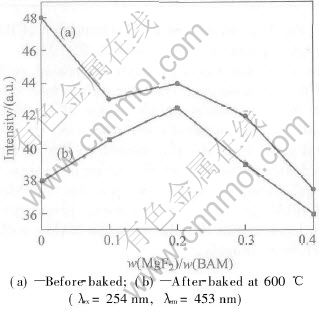
Fig.2 Photoluminescent intensities of MgF2-coated BAM phosphors as function of
mass ratio MgF2 to BAM
After baked at 600�� for 30min the luminescent intensity at 0.2% becomes the maximum (line b). This is because at lower mass ratio the coating could not cover the BAM phosphor particles completely to prevent BAM from oxidation effectively. High mass ratio results in high reflectance and low transmission ratio, which causes low luminescent intensity.
Fig. 3 shows the emission spectra of the samples coated with 0 and 0.2% MgF2. It indicates that the peak positions are not remarkably changed. Before baked the luminescent intensity of the coated is slightly lower than that of the uncoated. After baked at 600�� for 30min, the luminescent intensity of the coated BAM becomes 12% higher than that of the uncoated.
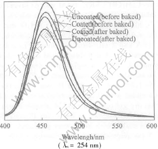
Fig.3 Emission spectra of coated and uncoated BAM phosphors before and after baked
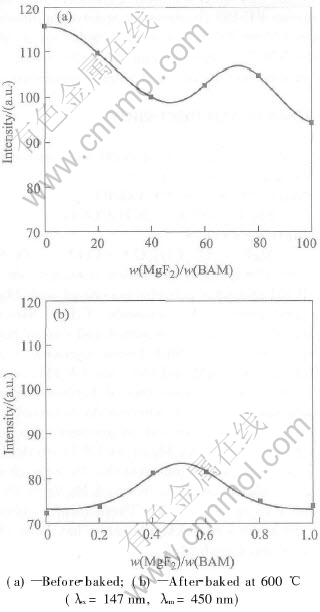
Fig.4 Photoluminescent intensities of MgF2-coated BAM phosphors as function of mass ratio of MgF2 to BAM
As shown in Fig.4(a), when irradiated by 147nm an extremum is observed at about 0.7%. Thus the thickness at about 0.7% is the optimum for reducing reflectance under 147nm. However, the maximum at about 0.5% is 15% higher than the uncoated��s and the curve is nearly a Gaussian distribution after baked at 600�� for 30min (Fig.4(b)). It is considered that besides the influence of the coating thickness, trace MgO formed at 600��[7, 14] in the coatings diffuses to the surface of BAM, and may influence the luminescent properties of BAM under 147nm excitation. Furthermore, the luminescence mechanism under VUV is different from that under UV, which may cause the different optimum thicknesses[15]. Further detail investigation is presently underway.
4 CONCLUSIONS
Blue emitting BAM phosphor for application in PDP is successfully coated with MgF2-coatings by a sol-gel process. The coatings were confirmed by XPS and SEM. The results indicated that the optimum anti-degradation properties were obtained at the mass ratio of 0.2% under 254nm excitation and 0.5% under 147nm excitation, respectively. As a conclusion, the sol-gel coating process is a promising method to protect the phosphor powders, and improves the phosphor��s anti-thermal degradation properties under UV and VUV excitation for application in display and lamps.
REFERENCES
[1]Yokota K, Zhang S X, Kimura K, et al. Eu2+-activated barium magnesium aluminate phosphor for plasma displays-Phase relation and mechanism of thermal degradation [J]. J Luminescence, 2001, 92: 223-227.
[2]PENG Guo-xian. Luminance degradation of PDP phosphor [J]. J Electron Device, 2001, 24(3): 245-251.
[3]J��stel T, Rhonda C, Weiler V. Plasma Picture Screen with Coated Phosphor [P]. US 6602617, 2003.
[4]J��stel T, Nikol H. Optimization of luminescent materials for plasma display panels [J]. Adv Mater, 2000, 12(7): 527-530.
[5]Do Y R, Park D H, Kim Y S . Phosphor for a Plasma Display Device Coated with a Continuous Thin Protective Layer and Method of Manufacture [P]. US 20020039665, 2002.
[6]Hirofumi M, Tomofumi M, Tsutomu K. Oxidation-Resistant Phosphor and Production Method Therefore [P]. JP 2001200249, 2001.
[7]Chau C N. Phosphor with Modified Surface Composition and Method for Preparation [P]. US 5695685, 1997.
[8]CUI Hong-tao, ZHANG Yao-wen, HONG Guang-yan. The surface coating technology of phosphor [J]. Functional Materials, 2001, 32(6): 564-567.(in Chinese)
[9]Lin C C, Tsai K L, Ozawa L. Phosphor Particle with Antireflection Coating [P]. US 5792509, 1998.
[10]XU Zhi-yuan, SUN Da-ming, LI Ai-xia, et al. X-ray diffraction analysis of the oxidation of MgF2 [J]. J Chinese Ceramic Society, 2002, 30(4): 505-508.(in Chinese)
[11]Hiroyuki K, Masaki A. Phosphor for Plasma Display Panel and Phosphor ink [P]. JP 2000087030, 2000.
[12]Tada M, Fujihara S, Kimura T. Sol-gel processing and characterization of alkaline earth and rare-earth fluoride thin films [J]. J Mater Res, 1999, 14(4): 1610-1616.
[13]Fujihara S, Tada M, Kimura T. Controlling factors for the conversion of trifluoroacetate sols into thin metal fluoride coatings [J]. J Sol-gel Sci Technol, 2000, 19: 311-314.
[14]Fujihara S, Tada M, Kimura T. Preparation and characterization of MgF2 thin film by a trifluoroacetic acid method [J]. Thin Solid Films, 1997, 304: 252-255.
[15]WANG Yu-hua, GUO Xuan, Endo T, et al. Identification of charge transfer (CT) transition in (Gd, Y)BO3:Eu phosphor under 100-300nm [J]. J Solid State Chem, 2004, 177: 2241-2247.
Foundation item: Project(50272026) supported by the NSFC; Project(2003AA324020) supported by the Hi-tech Research and Development Program of China
Received date: 2004-11-20; Accepted date: 2005-01-18
Correspondence: WANG Yu-hua, Professor, PhD; Tel: +86-931-8912079, Fax: +86-931-8913554; E-mail: wyh@lzu.edu.cn
