
J. Cent. South Univ. Technol. (2011) 18: 536-541
DOI: 10.1007/s11771-011-0728-0![]()
Sliding mode robust controller for automatic rectification of shield machine
YUE Ming(����)1, 2, SUN Wei(��ΰ)2, WEI Jian(κ��)2
1. School of Automotive Engineering, Dalian University of Technology, Dalian 116028, China;
2. School of Mechanical Engineering, Dalian University of Technology, Dalian 116028, China
? Central South University Press and Springer-Verlag Berlin Heidelberg 2011
Abstract:
According to the actual engineering problem that the precise load model of shield machine is difficult to achieve, a design method of sliding mode robust controller oriented to the automatic rectification of shield machine was proposed. Firstly, the nominal load model of shield machine and the ranges of model parameters were obtained by the soil mechanics parameters of certain geological conditions and the messages of the self-learning of shield machine by tunneling for
Key words:
shield machine; rectification; sliding mode; robust; upper bound��
1 Introduction
Due to the complicated and volatile working environment, the shield machine is likely to deviate from the design axis and the moving trajectory is just like snaking, and then, the deviation phenomena will take place under the influence of stratigraphic fluctuation, disproportionation of thrust force and other factors. The trajectory rectification is an important issue of shield tunneling. During the previous construction, due to the lack of load model of shield machine, the rectification relies on the manual regulation of the operator, which depends entirely on the experiences with low control precision. If the automatic control technology can be applied to the trajectory rectification, the automatic rectification will be helpful not only to improve the construction environment and avoid the construction danger [1], but also to reduce the operations by experience and improve the control precision. So, the automatic rectification technology has become a development tendency of the rectification technology of the shield machine [2].
During the processing of automatic rectification of shield machine, there are two key issues that should be solved: one is to determine the mechanism model of the peripheral force of the shield machine, and the other is to propose an effective attitude control method. Due to the strong nonlinear characteristics of force acting on the shield machine, the precise load model of shield machine is difficult to establish [3]. Therefore, many scholars apply fuzzy control strategy, which has little dependence on the precise model, to the automatic control of shield machine presently. For example, KUWAHARA et al discussed the applicability of fuzzy control in shield excavation control. KURAOKATOYO applied fuzzy control to the excavation management in the extending construction of Fukuichi High-speed Line 1 in Japan. URASAWAGI et al introduced the applicability of control theory based on artificial intelligence and fuzzy theory in a deep and long tunnel construction. HU et al developed the control system of tunnel axis using fuzzy control technology, but it was nearly impossible to be applied to the practical control of oil pressure because it was essentially a consulting system. According to the control characteristic of shield machine, LI et al [4] proposed a new design method of fuzzy controller called ��earlier separate and later merge��. Because of little dependence on precise load model of the shield machine, the fuzzy control strategy has many disadvantages such as low control precision, limited adaptive ability, unavoidable steady-state error and irregular oscillations.
Fortunately, according to the practical construction, the nominal load model of shield machine and the ranges of model parameters can be obtained through the analysis of soil mechanics parameters of certain geological conditions and self-learning of shield machine from tunneling for several previous segments. Theoretically, the ranges of model parameters can be predicted as long as the geological condition is known. Based on the engineering practice mentioned above, the sliding mode robust controller is investigated in this work because this control scheme is less restricted by the precise load model of the system. The asymptotically stable controller can be designed as long as the model parameters and ranges of disturbance are known [5].
2 Forces analysis of shield machine
Attitude deviation generally contains orientation deviation and rolling deviation [6-7]. According to the construction experiences and preliminary theoretical analysis, the rolling deviation of the shield machine is small and can be adjusted by changing the rotating direction of the cutterhead. Thus, only the orientation deviation, containing pitch deviation in the vertical plane and deflection deviation in the horizontal plane, is discussed in this work. In most cases, coupling phenomenon exists between these two kinds of deviations. However, the adjustment quantity of the angle is less than or equal to 2 mm/m in a segment length [8]. Then, this coupling phenomenon is limited to be considered as an external disturbance when the controller is designed.
To analyze the forces, the following assumptions are introduced: the shield is considered as a rigid body with a mass of m, a length of L, a radius of R, an outer diameter of Ds and a cutterhead diameter of Dc. The body coordinate of shield machine OXYZ is established, as shown in Fig.1. The point O is assumed to be set at the centre of shield tail. The propulsion system of shield machine is composed of a series of hydraulic cylinders to implement the transmission, distribution and control of the power. The hydraulic cylinders are generally divided into four regions in order to control the tunneling direction, and the same region serves as a group [9]. Here, the equivalent forces of upper, lower, left and right cylinders are expressed by Fu, Fd, Fl and Fr (Fig.1). Then, the force analysis of the shield in the vertical plane and in the horizontal plane will be carried out successively.
2.1 Forces analysis in vertical plane
The loads acting on the shield which affect the pitch deviation in vertical plane are composed of several forces [10]: shield weight m0g; thrusts of up and low hydraulic cylinders, Fu and Fd; earth pressure on the shield face F1; earth pressure on the upside and downside of shield, F2 and F3; friction force, F2�� and F3��. The load model of the shield in vertical plane is illustrated in Fig.2.
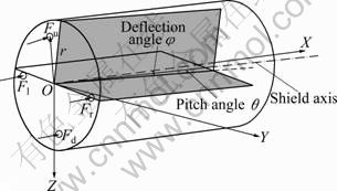
Fig.1 Body coordinates of shield machine
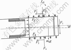
Fig.2 Load model of shield in vertical plane
If fv0 is used to express the equivalent resultant moment of F1, F2, F3, F2�� and F3�� about Y axis, then it can be obtained by the following equation.
1) When the shield deflects upwards:
![]() (1)
(1)
2) When the shield deflects downwards:
![]() (2)
(2)
2.2 Forces analysis in horizontal plane
Similarly, the loads acting on the shield which affect deflection deviation in the horizontal plane are composed of several forces: thrust of left and right hydraulic cylinders, Fl and Fr; earth pressure on the shield face F1; earth pressure on the left side and right side of shield, F4 and F5; friction force, F4�� and F5��. The load model of the shield in horizontal plane is illustrated in Fig.3.
If fh0 is used to express the equivalent resultant of F1, F4, F5, F4�� and F5�� about Z axis, it can be obtained by the following equations.
1) When the shield deflects to the left:
![]() (3)
(3)
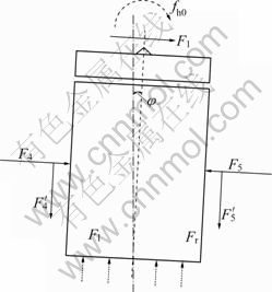
Fig.3 Load model of shield in horizontal plane
2) When the shield deflects to the right:
![]() (4)
(4)
3 Design of sliding mode robust controller
3.1 Controller for rectifying pitch angle
Essentially, the moment caused by the difference between forces of upper and lower cylinders is the control input of the shield in the vertical plane [11-12], which can be represented by
![]() (5)
(5)
m0, ��v0, kv0, l0, fv0, Jv0 are assumed to be the normal values, and ��m, ����v, ��kv, ��l, ��fv, ��Jv are the unknown variation domains caused by the unmodeled dynamics factors, such as soil changeable amount in chamber and the modeling errors of the system. All of them can be estimated from the preceding excavation:
m=m0+��m, ��v=��v0+����v, kv=kv0+��kv, l=l0+��l, fv=fv0+��fv, Jv=Jv0+��Jv
Note that ��Jv is the variation of moment caused by the existence of ��m and ��l. In addition, because external disturbances are unavoidable during excavation, w(t) is introduced to represent such disturbances. Ultimately, the dynamic model about pitch angle �� can be obtained by
![]() (6)
(6)
where
![]()
If the desired rectification trajectory is expressed by ![]() the tracking error can be defined as e= ��d-��, and then,
the tracking error can be defined as e= ��d-��, and then, ![]() and
and ![]() Under certain geological condition, the upper bounds of system parameters can be estimated and defined as
Under certain geological condition, the upper bounds of system parameters can be estimated and defined as ![]()
![]()
![]()
![]()
![]()
![]() and
and ![]() correspondingly. Meanwhile, the time-varying gain coefficient
correspondingly. Meanwhile, the time-varying gain coefficient ![]() is given by
is given by
![]()
![]()
The control input of system can be obtained by
![]()
![]() (7)
(7)
where ![]() c, ��, �� are all positive constants; sgn(��) is a sign function.
c, ��, �� are all positive constants; sgn(��) is a sign function.
Theorem 1: Consider the rectifying dynamic system (Eq.(6)), which is about the pitch angle of shield machine in vertical plane. Using the control law (Eq.(7)), the tracking errors are globally uniformly bounded and
![]() as t����.
as t����.
Proof: Suppose that the Lyapunov function is
![]()
where ![]() and c>0 [13]. Clearly, V��0. The time differential of V is given by
and c>0 [13]. Clearly, V��0. The time differential of V is given by

With the substitution of controller (Eq.(7)), ![]() can be obtained by
can be obtained by

According to the Lyapunov theorem [14-15], Theorem 1 is proven.
3.2 Controller for rectifying deflection angle
The moment caused by the difference between the forces of left and right cylinders is the control input of the shield in the horizontal plane, which can be represented by
![]() (8)
(8)
For clarifying, the subscript ��h�� is applied to the symbolic representation of the rectifying deflection angle, which is the same as ��v�� in the dynamic model of the pitch angle. Let v(t) represent the external disturbance, then the dynamic model about deflection angle �� of the shield can be obtained by
![]() (9)
(9)
where fh0 represents the resultant resistance moment of F1, F4, F5, F4�� and F5��; the uncertainty term of the shield machine can be given by
![]()
If the desired rectification trajectory is expressed as ![]() the tracking error is defined as
the tracking error is defined as ![]()
![]() and then
and then ![]()
![]() Similarly, under a certain geological condition, the upper bounds of the system parameters and v(t) can also be estimated and the time-varying gain coefficient
Similarly, under a certain geological condition, the upper bounds of the system parameters and v(t) can also be estimated and the time-varying gain coefficient ![]() is given by
is given by
![]()
Then, the control input of system can be obtained by
![]()
![]() (10)
(10)
where s, c, ��, �� and sgn(��) are the same as Eq.(7).
Theorem 2: Consider the rectifying dynamic system (Eq.(9)), which is about the deflection angle of shield machine in horizontal plane. Using the control law (Eq.(10)), the tracking errors are globally uniformly
bounded and ![]() as t����.
as t����.
Proof: Suppose that Lyapunov function is
![]()
where ![]() and c>0. Clearly, V��0. The time differential of V is given by
and c>0. Clearly, V��0. The time differential of V is given by
![]()
![]()
With the substitution of controller (Eq.(10)), ![]() can be obtained by
can be obtained by
![]()
![]()
Then, Theorem 2 is proven.
To eliminate chattering phenomenon of the system, the sign function sgn(s) in the controller (Eqs.(7) and
(10)) can be replaced by the continuous function![]() .
.
4 Simulation
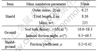
Simulation is carried out based on the construction data. The soil layers mainly include grey sandy silt layer, grey mucky clay layer and grey silty clay layer. Based on the assumption that the shield machine excavates through mixed ground mentioned above, the simulation parameters are listed in Table 1.
Table 1 Main simulation parameters
1) Rectifying pitch angle
Note that the ground values decide the normal model and uncertain domain of the rectifying dynamic models. By the analysis of the previous tunneling data and virtual prototype simulation, the normal values of the shield machine are preliminarily set as follows: m0=235 t, ��v0=0.5, kv0=120 kN/m, meanwhile, the uncertainties of the system is given by ����v=0.15cos(0.6��t), ��kv= 3sin(0.6��t) to simulate the drastic change of the soil layers. Additionally, the system disturbance is supposed to be w(t)=20sin(10t) (kN?m). In this case, the initial value of pitch angle is assumed to be ��0=35��� 10.18 mm/m, which should be adjusted to ��d=30��� 8.73 mm/m after the shield machine has tunneled a length of a segment. If the tunneling time is 60 min, the expectation equations of the pitch angle are as follows: ��d=35-0.083 3t, ![]() -0.083 3��/min. The controller parameters in controller (Eq.(7)) are chosen as follows: c=2, ��=2, ��=2, ��=0.02.
-0.083 3��/min. The controller parameters in controller (Eq.(7)) are chosen as follows: c=2, ��=2, ��=2, ��=0.02.
The tracking path and error of the pitch angle are shown in Fig.4(a) and Fig.4(b), respectively. The angular velocity of the pitch angle is illustrated in Fig.5. The thrusts of upper and lower hydraulic cylinders are shown in Fig.6.
2) Rectifying deflection angle
The initial value of deflection angle is assumed to be ��0=48���13.96 mm/m, which should be adjusted to ��d= 43'��12.51 mm/m in a tunneling segment length. In equal time interval, the expectation equations of the pitch angle are as follows: ��d(t)=48-0.083 3 t, ![]() -0.833��/min. The controller parameters in controller (Eq.(10)) are chosen as follows: c=2, ��=2, ��=2, ��=0.01.
-0.833��/min. The controller parameters in controller (Eq.(10)) are chosen as follows: c=2, ��=2, ��=2, ��=0.01.
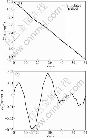
Fig.4 Tracking path (a) and error (b) of pitch angle
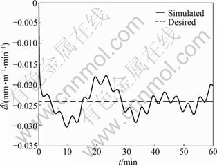
Fig.5 Tracking curve of angular velocity of pitch angle
The tracking path and error of the deflection angle of the shield are illustrated in Fig.7(a) and Fig.7(b), respectively. Its angular velocity is shown in Fig.8. The thrusts of left and right hydraulic cylinders are illustrated in Fig.9.
The simulation results show that the tracking error of pitch angle is between -0.03 mm/m and 0.02 mm/m, which is acceptable for the practical tunneling. Without the influence of gravity, m0g, the tracking error of deflection angle is less, between -0.013 mm/m and 0.012 mm/m. Based on the hypothesis ranges of soil parameters, the proposed sliding mode robust controller can realize rectification and also can effectively suppress the parameter fluctuation and external disturbance. In addition, the sliding mode robust controller can ensure steady and robust rectification process.
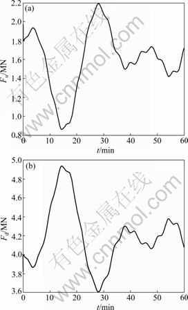
Fig.6 Thrusts of upper (a) and lower (b) hydraulic cylinders
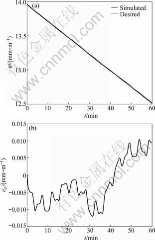
Fig.7 Tracking path (a) and error (b) of deflection angle
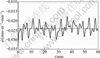
Fig.8 Tracking curve of angular velocity of deflection angle
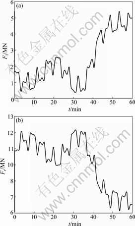
Fig.9 Thrusts of left (a) and right (b) hydraulic cylinders
5 Conclusions
1) The rectifying process is decoupled into two subsystems, pitch in vertical plane and deflection in horizontal plane. It is feasible because a very small angle should be permitted in one segment of shield excavation, thus the coupling dynamics between the two subsystems could be considered as disturbances.
2) Because the complex forces around the shield are hard to be accurately described, the accurate mechanics model of the shield excavation could be hardly applied to design the system controller. However, the upper bound of the system parameters and the disturbances could be achieved by the analysis of the soil mechanics parameters of certain geological conditions and self-learning of shield machine from tunneling for several previous segments. The sliding mode robust controller is proposed based on this upper bound information, and the simulation results verify the effectiveness of the proposed controller.
References
[1] ZHOU Qi-cai, CHEN Jun-ru, HE Zi-qiang. Matlab-enabled fuzzy deviation controller implementation for shield excavators [J]. Chinese Journal of Mechanical Engineering, 2007, 5(4): 414-419. (in Chinese)
[2] WATANABE T, TANAKA T, ABE T. Development of a new composite structure segment for large diameter shield tunnel [J]. Tunneling and Underground Space Technology, 2004, (19): 449-450.
[3] WU Li, QU Fu-zheng. Discrete element simulation of mechanical characteristic of conditioned sands in earth pressure balance shield tunneling [J]. Journal of Central South University of Technology, 2009, 16(1): 1-6.
[4] LI Hui-ping, XIA Ming-yao. Fuzzy algorithm for control of shield machine [J]. Journal of Tongji University: Natural Science, 2003, 31(7): 824-827. (in Chinese)
[5] LIU Kuo, GUO Da-meng, LIU Jie. Research and simulation of hydraulic excavator��s adaptive fuzzy sliding control [J]. Journal of Northeastern University: Natural Science, 2009, 30(11): 1649-1652. (in Chinese)
[6] HU G, GONG L. Thrust hydraulic system of shield tunnel boring machine with pressure and flow compound control [J]. Chinese Journal of Mechanical Engineering, 2006, 42(6): 124-127.
[7] YUE Ming, WEI Jian, SUN Wei, GUO Zheng-gang. Dynamic mechanism and key rectification techniques of shield machine in the vertical plane [C]// Intelligent Robotics and Applications. Heidelberg: Springer, 2009: 412-422.
[8] ZHOU Zhen-guo, GUO Lei, GUO Wei-she. The construction attitude control and segment selection of shield machine [J]. West-China Exploration Engineering, 2002(5): 124-127. (in Chinese)
[9] MITSUTAKA S, APHICHAT S, ASCE M. Theoretical model of shield behavior during excavation. ��: Theory [J]. Journal of Geotechnical and Geoenvior-Mental Engineer, 2002, 128(2): 138-155.
[10] APHICHAT S, MITSUTAKA S, KAYUKAWA K. Theoretical model of shield behavior during excavation. ��: Application [J]. Journal of Geotechnical and Geoenvior-mental Engineer, 2002, 128(2): 156-165.
[11] MAES J, MELKEBEEK J A. Speed-sensorless direct torque control of induction motors using an adaptive flux observer [J]. IEEE Transactions on Industry Application, 2000, 36(3): 778-785.
[12] ADNAN D, MUSTAFAH G. Design and implementation of a new sliding-mode observer for speed sensorless control of induction machine [J]. IEEE Transactions on Industry Application, 2002, 49(5): 1177-1182.
[13] ZHANG Xi-zheng, WANG Yao-nan, YANG Min-shen. Doubly-sliding-mode based sensorless robust control of PMSM [J]. Electric Machines and Control, 2008, 12(6): 696-700. (in Chinese)
[14] FENG G. Controller synthesis of fuzzy dynamic systems based on piecewise Lyapunov functions[J]. IEEE Transactions on Fuzzy Systems, 2003, 11(5): 605-612.
[15] FENG G. Stability analysis of discrete-time fuzzy dynamic systems based on piecewise Lyapunov functions [J]. IEEE Transactions on Fuzzy Systems, 2004, 12(1): 22-28.
(Edited by YANG Bing)
Foundation item: Project(2007CB714006) supported by the National Basic Research Program of China
Received date: 2010-01-13; Accepted date: 2010-04-02
Corresponding author: YUE Ming, PhD; Tel: +86-411-84707435; E-mail: yueming@dlut.edu.cn
