

Analysis of rolls deflection of Sendzimir mill by 3D FEM
YU Hai-liang(������)1, LIU Xiang-hua(���)1, LEE Gyoo Taek2
1. State Key Laboratory of Rolling and Automation, Northeastern University, Shenyang 110004, China;
2. POSCO Technical Research Laboratories, Pohang 790-785, Korea
Received 28 June 2006; accepted 16 February 2007
Abstract:
The deflection of rolls of Sendzimir mill with double AS-U-Roll was simulated by finite element method(FEM). The influences of rolling pressure, strip width and rolls-assignment on rolls deflection were analyzed. The results show that the work roll deflection increases with the increase of rolling pressure and the reduction of work roll radius, but the rigid displacement of work roll slightly changes; the work roll end might appear negative displacement for the narrow strip width and high rolling pressure that might cause the contact of work rolls. The research results are significant for guiding production and theoretical analysis of the rolls system of Sendzimir mill.
Key words:
roll deflection; Sendzimir mill; finite element method; double AS-U-roll;
1 Introduction
Sendzimir mill is made up of work rolls, 1st intermediate rolls (1st IMR), 2nd intermediate rolls (2nd IMR) and backup rolls, which is widely used for rolling aluminum foil, stainless steel, Si-steel, high degree of accuracy sheet, etc, for small diameter of work roll, high rigidity and high precision of mill. Till now there have been more than 400 20-high mills in the world. Nowadays, there are two kinds of AS-U-roll control methods in Sendzimir mill: single AS-U-roll and double AS-U-rolls, and the latter is shown in Fig.1. Because the rolls system of Sendzimir mill is complex, researchers have done many works on it, such as KIM et al[1], ASANO et al[2], RINGWOOD[3], RAY et al[4], SCHEIDER et al[5], HARA[6], BERGER et al[7], FOREHLING[8], PAN[9]. They generally research the strip shape control method or the rolls assignment or the friction and failure of rolls, etc. However, there are still not any report about the research by finite element method(FEM).
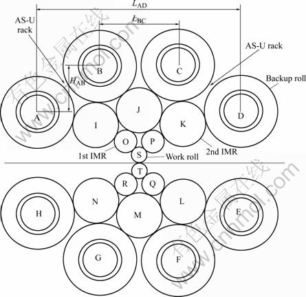
Fig.1 Schematic diagram of Sendzimir mill with double AS-U-rolls
Strip shape control and material macrostructure property control are two key topics of strip rolling research. Roll deflection and roll flattening are the direct influence factors of strip shape. Analysis of the roll deflection is significant for analyzing strip shape. FEM [10-13] is one of the methods used to analyze the roll deflection. But there are no research reports about Sendzimir mill by FEM.
Explicit dynamic FEM is widely used to analyze metal deformation problems[14-17] for quick calculating speed and easily dealing with contact problem. In this study, this method was used to simulate the rolls deflection of Sendzimir mill, and the influences of rolling pressure, strip width and rolls-assignment on rolls deflection were analyzed.
2 FE simulation
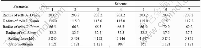
During simulation, 7 schemes were employed, and scheme 1 was considered the criterion of comparison. Schemes 1-3 were used to analyze the influences of rolling force on rolls deflection; schemes 1, 4 and 5 for analyzing the influences of strip width on rolls deflection; and schemes 1, 6 and 7 for analyzing the influences of rolls assignment on rolls deflection.
The backup rolls A-D are AS-U-rolls that are made up of a series of parts, such as backing bearing, mandrel, etc. For simplifying simulation model, the backup rolls were divided into 13 parts (7 necks, 6 barrels), as shown in Fig.2.
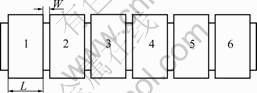
Fig.2 Simplified model of backup roll
In the simulation, the main parameters are as follows: barrel length of roll 1 346 mm, density of roll 7 850 kg/m3, elastic modulus of roll 220 GPa, Poisson ratio of roll 0.3, LAD 1 086 mm, LBC 415 mm, HAB 241.7 mm, W 64 mm, L 171 mm. And other parameters are listed in Table 1.
Table 1 Geometrical parameters and computational conditions
Owing to the symmetry of rolls system, the above 10 rolls (rolls A-D, I-K, O, P, S) were included in the geometric model. During simulation, the necks of backup rolls were considered to be rigid, which were constrained to UX, Y, Z=0 by AS-U racks. Other parts were considered elastic parts. The rolls were meshed by the elements with 8 nodes and hexahedron, and the elements near contact positions between rolls were refined (in the simulation, there were 42 contact pairs). The rolling pressure (obtained by Stone��s equation according to the deformation resistance of strip and the rolling schedules, which was assumed invariable during rolling process) was loaded on nodes at the bottom of the work roll. The geometrical model and meshing of rolls system were shown in Fig.3.
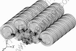
Fig.3 Geometry and meshing of Sendzimir mill
3 Results and discussion
Owing to the symmetry of rolls A and D, B and C, I and J, O and P, the roll deflection of rolls A, B, I, J, O and S were analyzed as follows.
Fig.4 shows the rolls deflection under variable rolling forces. From Fig.4(a), the rigid displacement of roll S is 0.49 mm and the maximum deflection of roll S is 1.27 mm for scheme 1; similarly, 0.60 mm and 1.06 mm for scheme 2, 0.57 mm and 0.77 mm for scheme 3. From Fig.4(b), the rigid displacement of roll O is 0.41 mm and the maximum deflection of roll O is 0.44 mm for scheme 1; similarly, 0.38 mm and 0.43 mm for scheme 2, 0.30 mm and 0.33 mm for scheme 3. It can be found that the roll deflection increases and the rigid dislocation changes slightly with the increase of rolling force. From Figs.4(c) and (d), it can be found that the maximum deflection of roll J is smaller than that of roll I. Similarly, the maximum roll deflection of roll B is smaller than that of roll A.
Fig.5 shows the rolls deflection under various strip widths. When the strip width reduces from 1 121 to 987 mm, the rigid displacement and deflection of roll S decrease. However, when the strip width reduces from 987 to 853 mm, the displacement of end of roll S becomes negative. Meanwhile, the maximum of roll deflection increases, which also appears in rolls O and I. From Figs.5(e) and (f), the deflection of parts 2-4 of rolls A and B changes little, but that of the parts 1 and 6 changes obviously.
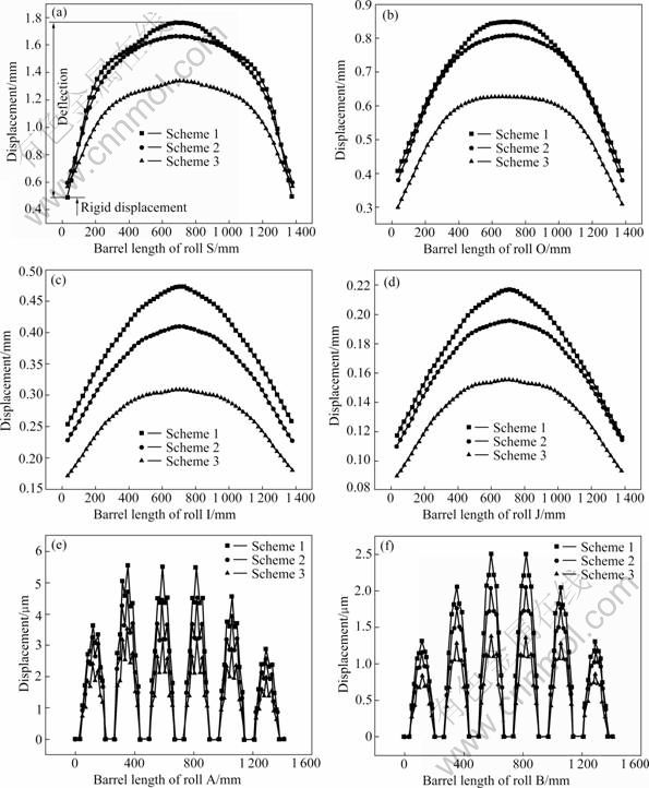
Fig.4 Roll deflection under variable rolling forces: (a) Roll S; (b) Roll O; (c) Roll I; (d) Roll J; (e) Roll A; (f) Roll B
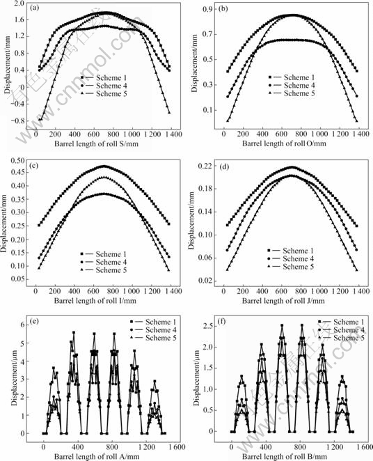
Fig.5 Roll deflection under variable strip widths: (a) Roll S; (b) Roll O; (c) Roll I; (d) Roll J; (e) Roll A; (f) Roll B
Fig.6 shows the rolls deflection under variable rolls-assignment. From Fig.6(a), the maximum of roll S deflection increases with the reduction of roll radius, and it increases with the reduction of the radius of 1st IMR when the work roll radii are equal. From Fig.6(b), the roll deflection increases as the 1st IMR radius reduces. From Figs.6(e) and (f), the rolls have the same radius, but they have different roll deflections. The main reason is the change of acting force of rolls system.
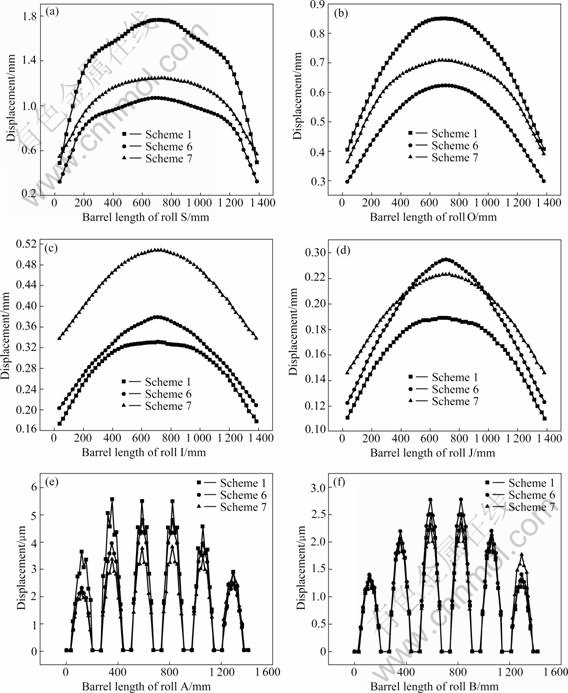
Fig.6 Roll deflection under variable rolls-assignments: (a) Roll S; (b) Roll O; (c) Roll I; (d) Roll J; (e) Roll A; (f) Roll B
The roll deflection and the rigid displacement of work roll are important influence factors of strip exit profile, which are affected by the 1st IMR, 2nd IMR and backup roll radii, the acting force distribution in 20-high Sendzimir mill, the position of AS-U racks and the profile of roll J, etc. The AS-U racks position and the profile of roll J are used to control the strip shape during rolling processes. It will provide suitable theoretical guide for adjusting AS-U-rolls to analyze the rolls deflection without the change of AS-U racks position.
During rolling processes, there are many influence factors of roll deflection, e.g. physical dimensions and material attribution of rolls and strip, rolling schedules, tensions, etc. It is undoubted that the rolling pressure, the strip width and the rolls-assignment are the most important factors.
There are many influencing factors of rolling force, e.g. rolling schedule, tension, work roll radius, friction and material attribution etc. From the above results, the rolls deflection reduces with decreasing rolling force. When rolling the same physical dimension strip with different material attributions, the strip with low deformation resistance should reduce the bend deformation of backup roll by adjusting AS-U-rolls.
The strips with different widths are rolled for variable users. In this paper, the rolls deflection was analyzed with three kinds of strip widths. From the results, the rigid displacement of the end of work roll is not a positive value but a negative value when the strip width is narrow and the rolling force is big. Under this condition, the main reason is that the roll flattening along barrel length direction is not symmetrical. When the strip width is narrow, the roll flattening in the roll middle part is big and that in other parts are small, and the barrel length is long, so the end of work roll lowers, as shown in Fig.7.
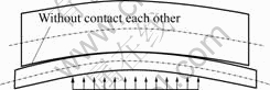
Fig.7 Roll displacement with narrow strip width
For Sendzimir mill, there are hundreds of rolls- assignment conditions. When the rolling force distribution is identical, the acting force of rolls system will change with the change of rolls-assignment, which will cause variable rolls deflection, so it is needed to adjust the AS-U-rolls. From the above results, the increase of work roll radius will reduce the work roll deflection. However, it might reduce the rolling power, even can��t roll some thin strip. So when the work roll radius is not changed, it can suitably increase the radius of 1st IMR and reduce the radius of 2nd IMR.
4 Conclusions
1) The rolls deflection of Sendzimir mill under different rolling forces, strip widths and rolls- assignments was simulated by explicit dynamic FEM, which supplies a method for dealing with complex rolling problems.
2) The work roll deflection increases with the increase of rolling force and the reduction of work roll radius, but the rigid displacement of the work roll changes little.
3) The work roll end might appear negative displacement for narrow strip width and high rolling pressure, which should be avoided for reducing the wear of work roll end.
[1] KIM J T, YI J J, HAN S Y. Shape control of alloy steel rolled by Sendzimir mill [J]. KSME Journal, 1996, 10(3): 277?285.
[2] ASANO K, TAKAHASHI H, MIYATA T, KOHIRO Y. Stabilization of tension control in reverse rolling mills using state feedback [J]. Tetsu To Hagane, 2004, 90(11): 958?963. (in Japanese)
[3] RINGWOOD J V. Shape control systems for Sendzimir steel mills [J]. IEEE Transactions on Control Systems Technology, 2000, 8(1): 70?86.
[4] RAY A, MUKHERJEE D, SARKAR B, MISHRA S. Influence of microstructure on the premature failure of a 2nd intermediate Sendzimir mill drive roll [J]. Journal of Materials Engineering and Performance, 1994, 3(5): 649?656.
[5] SCHEIDER A, WERNERS R. Modeling and optimization for a 20-h cold rolling mill [J]. Iron and Steel Engineer, 1999, 76(3): 44?47.
[6] HARA K, YAMADA T, TAKAGI K. Shape controllability for quarter buckles of strip in 20-high Sendzimir mills [J]. ISIJ International, 1991, 31(6): 607?613.
[7] BERGER B, SCHULTE H, BENFER M, RINKE F W. Advanced 20-high mill technology [J]. Metallurgical Plant and Technology International, 2000, 23(6): 70?72, 74.
[8] FOREHLING P, RIECKMANN J, JATTA J. High tensile, light gage rolling with 20-h reversing cold mills [J]. Iron and Steel Engineer, 1999, 76(3): 41?43.
[9] PAN C. 20-High Mill and High Precise Cold Strip Rolling [M]. Beijing: Metallurgical Industry Press, 2003. (in Chinese)
KNAPINSKI M. FEM 3D analysis of roll deflection during plate rolling [J]. Metalurgija, 2005, 44(3): 175?178.
[10] ZHANG G M, XIAO H, WANG C H. Three-dimensional model for strip hot rolling [J]. Journal of Iron and Steel Research International, 2006, 13(1): 23?26.
[11] NILSSON A. FE simulations of camber in hot strip rolling [J]. Journal of Materials Processing Technology, 1998, 80/81: 325?329.
[12] XIAO W F, ZHANG L H, ZHU Z H. FEM analysis of casting roller intensity under aluminum strip high-speed casting condition [J]. Journal of Central South University of Technology: Natural Science, 2000, 31(6): 548?551.
[13] YU H L, LIU X H, ZHAO X M, WU D, KUSABA Y. Explicit dynamic FEM analysis of multipass vertical-horizontal rolling [J]. Journal of Iron and Steel Research International, 2006, 13(3): 26?30.
[14] WANG M, YANG H, SUN Z C, GUO L G, OU X Z. Dynamic explicit FE modeling of hot ring rolling process [J]. Trans Nonferrous Met Soc China, 2006, 16(6): 1274?1280.
[15] CHUNG W K, CHOI S K, THOMSON P F. Three-dimensional simulation of the edge rolling process by the explicit finite element method [J]. Journal of Materials Processing Technology, 1993, 38(1/2): 85?102.
[17] LIU X B, TAN J P, YI Y P. Stress field analysis of extra-height forging die using finite element method [J]. Journal of Central South University of Technology, 1999, 6(1): 59?62.
Foundation item: Project(50534020) supported by the National Natural Science Foundation of China
Corresponding author: YU Hai-liang; Tel: +86-24-83681803; Fax: +86-24-23906472; E-mail: yuhailiang1980@tom.com
Abstract: The deflection of rolls of Sendzimir mill with double AS-U-Roll was simulated by finite element method(FEM). The influences of rolling pressure, strip width and rolls-assignment on rolls deflection were analyzed. The results show that the work roll deflection increases with the increase of rolling pressure and the reduction of work roll radius, but the rigid displacement of work roll slightly changes; the work roll end might appear negative displacement for the narrow strip width and high rolling pressure that might cause the contact of work rolls. The research results are significant for guiding production and theoretical analysis of the rolls system of Sendzimir mill.
