
J. Cent. South Univ. (2018) 25: 681-689
DOI: https://doi.org/10.1007/s11771-018-3771-2

Comprehensive health assessment of shield tunnel structure based on prototype experiment
LI Pan(����)1, ZHANG Ya-wei(����Ϊ)2, JIANG Fu-yu(������)3, ZHENG Hu(֣��)3
1. School of Urban Rail Transportation, Soochow University, Suzhou 215131 China;
2. Shanghai Municipal Engineering Design Institute (Group) CO. LTD, Shanghai 200092, China;
3. School of Earth Science and Engineering, Hohai University, Nanjing 211100, China
 Central South University Press and Springer-Verlag GmbH Germany, part of Springer Nature 2018
Abstract:
Health state of shield tunnels is one of the most important parameters for structure maintenance. Usually, the shield tunnel is extremely long in longitude direction and composed by many segments. It is difficult to quantify the relationship between the structure damage state and shield tunnel structure deformation by the model test because of unpredictable effects of different scales between model test and prototype tunnel structure. Here, an in-situ monitoring project was conducted to study the excavation induced shield tunnel structure damage, which could be considered a prototype test on the tunnel deformation. The disaster performance of tunnel leakage, segment crack, segment dislocation and segment block drop-off during longitude deformation and cross-section ovality developments was analyzed. The results indicate that instead of the longitude deformation, the ovality value has the strongest correlation to the rest disease performance, which could be used as the assessment index of the tunnel health. For this tunnel, it is in health state when the ovality is less than 0.5%, and the serious damage could be found when the ovality value is higher than 0.77%. The research results provide valuable reference to shield tunnel health assessment and help complete the standard of shield tunnel construction.
Key words:
shield tunnel; health assessment; deformation; structure disease��
Cite this article as:
LI Pan, ZHANG Ya-wei, JIANG Fu-yu, ZHENG Hu. Comprehensive health assessment of shield tunnel structure based on prototype experiment [J]. Journal of Central South University, 2018, 25(3): 681�C689.
DOI:https://dx.doi.org/https://doi.org/10.1007/s11771-018-3771-21 Introduction
Metro has been proved as one of the most powerful and effective public transportation recently, especially in China [1, 2]. There were 25 cities in China with 3195.6 km subway lines in total till the end of 2015. The most developed metro system in China like Shanghai is located at estuary of Yangtze River on China��s east coast. The shield tunnel is widely used in such a geological environment, and it is very convenient and effective for constructing. However, lots of disease performance have been noticed on the construction of the previous metro tunnel structure, like tunnel deformation, leakage etc., which are impossible to avoid during the normal metro operation [3�C5]. Meanwhile, these diseases are getting worse with the metro operation and becoming a serious threat to the safety of the city metro system. Hence, the corresponding maintenance methods based on health assessment and detection of the tunnel structure are extremely important to keep metro operation safety [6�C8]. The damaging tunnel structures can show lots of different disease performances, which means that these disease performances could be the indexes to evaluate the health status of the tunnel structure.
The mechanisms of the tunnel structure damage are various because of the differences- complicated geological conditions and the specificity of shield tunnel construction methods, like huge aspect ratio, poly-linker between tunnel segments etc., which cause difficulty to choose the right index or indexes for the tunnel structure health assessment. People tried to use the fuzzy analytical hierarchy process (FAHP) by considering disease performance factors like geological conditions, deformation, water leakage, connector bolt deformation and breaking etc., comprehensively [9�C11]. They took the weights of different factors into account to assess the tunnel health and define the tunnel health state. However, the relationships of administrative subordination of these disease performances are not clear yet [12]. Recently, some researchers started to focus on using one disease performance as a single index to study the mechanism of tunnel disease [13�C15]. They try to build the connection between the tunnel deformation and structural mechanic characteristics, so that they could evaluate the tunnel health status [16, 17]. Even though, there still lack of solid experimental results to support their results. The model test in lab usually has been scaled by many times due to the characteristics of tunnel structure. Roles of reduced scale maintain a mystery in the results. But the prototype experiment requires damaging a whole tunnel structure, which would cost a lot. Normally, people are not doing this on purpose.
In this work, a full-size prototype test on the shield tunnel deformation was conducted but not on purpose. The studied shield tunnel shows serious damage due to the neighbor excavation. A couple of tunnel disease performances can be seen during the in-situ monitoring, such as leakage, segment crack, and segment dislocation. A comprehensive tunnel assessment was conducted based on this prototype experimental data. The ovality of the tunnel cross-section was found as an important index to evaluation the tunnel health, which has very stronger correlation with all other disease performances. The research results provide valuable reference to the future similar tunnel health assessment projects.
2 Project descriptions
The studied tunnel project was located at the estuary of Yangtze River on China��s east coast. The tunnel goes through the flat plain known as Yangtze River Delta, which features high groundwater table and thick soft clay. The shield tunnel belongs to a single-track circular tunnel with a minimum radius of curve of 600 m. The external diameter of the segment was 6.2 m. There were 6 segments in total to constitute an entire circular ring, including a key block (F), two pieces of adjacent blocks (L), and three pieces of standard blocks (B). As shown in Figure 1, the thickness of the segment was 35 cm, and the width of the ring was 1.2 m. The M30 bolts with 5.8 M mechanical properties were used as connectors between rings and segments, and the tunnel lining was applied.
There was an excavation at the northern of shield tunnel construction between the 60th and 260th rings, and the distance from the boundary of the excavation to the shield tunnel was in the range of 7.15 m to 13.08 m as shown in Figure 2(a). The soil properties at the site were explored in detail by a series of field exploration programs before and during the shield tunnel construction. In general, the site was characterized by clay, and the details of the soil conditions could be found in Figure 2(b). In the study region, the depth of the tunnel top was 9.985�C15.367 m, and the depth of the excavation was 14.4 m�C14.8 m. However, serious leakage happened during the excavation even the corresponding excavation protection measures were employed (Figure 3(a)). Meanwhile, lots of cracks,fissures, and local breaking of segment could also be observed. Hence, a comprehensive assessment was carried out to analyze the tunnel structural damage, including the longitudinal deformation (movement of the tunnel), cross-section deformation, cracks on tunnel segment and block drop off etc.
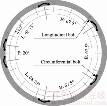
Figure 1 Ring structure of shield tunnel
3 Protocols of tunnel health assessment
3.1 Longitudinal and cross-section deformation of tunnel
The deformation of the shield tunnel structure, including longitudinal and cross-section deformation, is one of the most representative index of the shield tunnel diseases. The tunnel deformation could be a critical parameter to reflect the tunnel health state. In this study, the tunnel segment structure deformation in the vertical and horizontal directions was monitored quantificationally.
The longitudinal deformation of the tunnel includes the vertical settlement and the horizontal displacement. The vertical movement was monitored by the monitoring points located at the arch bottom and vault. There were 200 rings in the studied region; the arch bottom and vault monitoring points were settled every 10 rings. The cross-section deformation of the tunnel means the changing of the diameter in vertical and horizontal directions, which could be measured by four monitoring points as shown in Figure 3. Both the longitudinal and cross-section deformation data were collected every 24 h. Moreover, the segment cracks were also described to show the tunnel disease directly.
3.2 Cracks on segment
The excavation induced tunnel movement and the deformation, which could cause the cracks on the shield tunnel segment. The crack distribution, penetration and the joint damage between segments were all the important parameters which could reflect the health status of the shield tunnel structure. Here, these parameters including distribution and penetration of cracks and segments joint damage were evaluated by in-situ investigation.
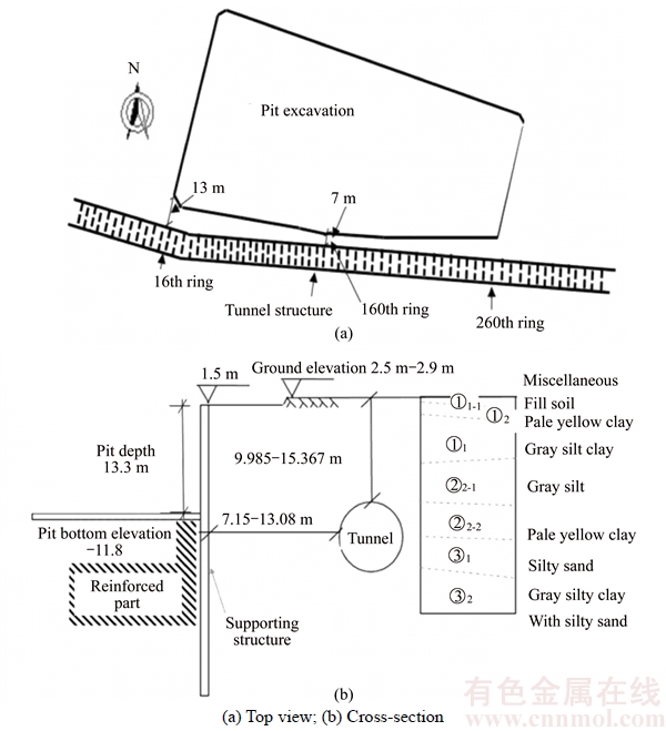
Figure 2 Space relationship between tunnel and excavation:
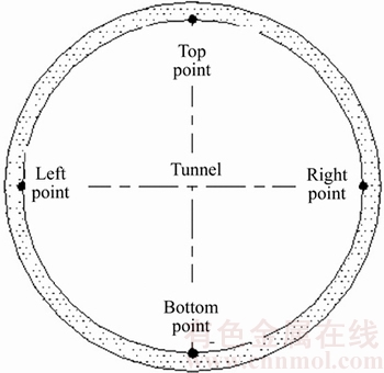
Figure 3 Cross-section deformation detection points (Top and bottom points are used to monitor diameter changing in vertical direction; left and right points are for diameter changing in horizontal direction)
The position of cracks could be located by the in-situ investigation. The corresponding crack lengths were measured by the tapeline. The segment joint damage measurement includes the location of the joint opening, the opening size and the longitudinal joint dislocation. The joint opening equals the measured value deducted by the structure opening value, which already existed before the damage. The leakage caused by the damage at the joint position could also be detected during the in-situ investigation, as shown in Figure 4.
4 Data analysis and discussions
4.1 Longitudinal deformation
The longitudinal deformation consists of the vertical settlement and the horizontal displacement, which could be used to show the general state of the tunnel longitudinal deformation. The longitudinal deformation can be calculated as follows:
c=a��b (1)
where c is the longitudinal deformation; a is the vertical settlement; and b is the horizontal displacement. a and b indicate the displacement in vertical and horizontal direction, respectively. Here,the deformation of tunnel is not considered, which will be introduced in detail in the next section. Both a and b are perpendicular to the tunnel direction.
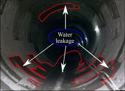
Figure 4 Typical tunnel leakage phenomenon as marked in red region
The measured data of the tunnel region are shown in Figure 5. Here, the vertically upward is defined as positive for the settlement, and the north is defined as positive for the horizontal displacement, respectively. The tunnel deformation curves indicate that the tunnel in the whole studied area is settling. The horizontal displacement of the tunnel was always positive, which was pointing to the constructing foundation excavation. The magnitude of the displacement fluctuates as the distance to the excavation boundary. The maximum horizontal displacement is about 53 mm happening around ring 161, where was the closest to the pit boundary. The horizontal displacement from ring 20 to 110 was relative stable, which was around 31 mm. The horizontal displacement increases along the ring number linearly from rings 110 to 160, and reaches the maximum value at ring 161.
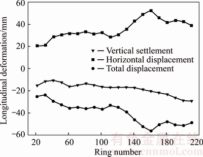
Figure 5 Tunnel longitudinal deformation along ring number
4.2 Cross-section deformation
The cross-section deformation of the tunnel was evaluated by the changing of diameters in vertical and horizontal directions. The ovality of the tunnel can be calculated by the following equation, which is an important parameter to show the tunnel cross-section deformation.
 (2)
(2)
where Dmax and Dmin are the maximum and minimum measured diameter of the tunnel cross- section, respectively; D is the standard tunnel diameter.
The horizontal and vertical diameters variation and the ovality of each measured ring are shown in Figure 6. The horizontal diameter change increases gradually with very small fluctuation as the ring number increases, which means that the tunnel was swelling in the horizontal direction. Conversely, the vertical diameter of the measured region decreases. The decreasing magnitude reaches the maximum value at ring 120, which was about 24 mm. The ovality of the tunnel cross- section increases with the ring number. The ovality curve shows two plateaus which are located at rings 41 to 81 and rings 161 to 210. The maximum ovality was 0.75% at ring 121, where the vertical diameter shrinks by 15 mm and horizontal diameter dilates by 24 mm. The closest position of the tunnel to the excavation was at ring 161, where the values of the horizontal diameter increasing and vertical diameter decreasing were 21 and 16 correspondingly and the ovality was 0.65%. The cross-section deformation for rings 41 to 81 was relatively homogeneous; the vertical diameter decreases by about 11 mm; the horizontal diameter increases by about 18 mm; and
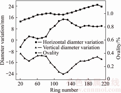
Figure 6 Tunnel cross-section deformation along ring number
the ovality was about 0.5%.
4.3 Statistical analysis of cracks
The systematic statistics of the cracks were also conducted, which shows that most of the segments have cracks. The majority crack strike was along the tunnel direction. The orientations of cracks are very similar, which indicates that the cracks are probably caused by the stress field during the same period. The typical cracks are shown in Figure 7, which were found at ring 51.
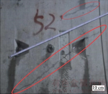
Figure 7 Typical cracks found at ring 51 during in-situ investigation (two long cracks are highlighted by ellipse)
To describe the crack positions conveniently, the tunnel cross-section was divided into 12 regions as shown in Figure 8. The in-situ investigation shows that there were 635 cracks in total in the studied 200 rings region. Most of cracks were observed in 5 clock to 7 clock regions, which were about 63% in total. 36% of cracks were found in 11 clock to 1 clock region. The crack distribution phenomena might be caused by the vertical diameter shrinking induced local tunnel extension in these regions. The rest region only has 1% of cracks. There were only a few cracks on the segments from rings 61 to 81. However, lots of cracks could be seen at rings 121, 161 and 201, which were close to the excavation.
The health state of segments joints is also a very important parameter to assess the tunnel health. In the study region, we did not find clear segments joints damages, even the leakages were found. But the segments joints splayed were found approximately every 5 rings, which were 11�C16 mm.
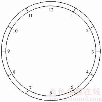
Figure 8 Schematic of clockwise segmentation of tunnel cross-section
5 Evolution mechanism of shield tunnel disease
The shield tunnel diseases include the vertical settlements, horizontal deformations, leakage, segment dislocation and the crack development on segment etc. [18]. However, it is barely seen one of these diseases happening individually. They might all interrelate. When one of these diseases happens, others would be seen at the same time [19]. For example, the loading-unloading process and the ground water level changing would induce the shield tunnel deformation [20�C22]. The tunnel structure leakage can cause the ground water decreasing, and the ground settlement might be trigged by the groundwater level decreasing [23, 24]. Meanwhile, the shield tunnel structure also deforms with the ground settlement [25]. Moreover, the segment cracks, dislocations were induced by the shield tunnel structure deformation, which would increase leakage speed and amplify leakage area [26].
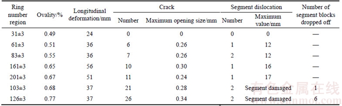
The typical disease evolution process of shield tunnel structure could be illuminated as the flow diagram shown in Figure 9. In real project, it is very hard to find a universal tunnel disease evolution mechanism which works to every case. Since each disease is interrelated with others, one representative control index could be chosen to assess the tunnel health. Figure 9 shows that almost all the diseases were linked to the tunnel structure deformation. In addition, the deformation of the tunnel structure is relative easy to be monitored, which could be used to describe the health state of the shield tunnel structure quantificationally.Table 1 shows the measured data of tunnel ovality, longitudinal deformation, cracks, segment dislocation and number of segment blocks drop off after the excavation. To compare each disease performance at the typical segment ring position, three rings behind and after the selected ring were also taken into account. The correlation of the longitudinal deformation between cracks segment dislocation and number of segment block drop off seems to be not that strong. However, the ovality of the tunnel after deformation presents stronger correlation between other tunnel disease performances, which indicates that the ovality could be a valuable index to assess the health status of the tunnel contracture.
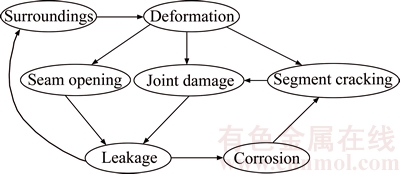
Figure 9 Disease evolution process of shield tunnel structure
Table 1 Statistical data of tunnel disease performance
All other disease performances developing with the ovality are plotted in Figure 10. The tunnel could be diagnosed as absolutely health state as the ovality is less than 0.5, which is corresponding to zone 1 in Figure 10. The typical segment surface in zone 1 is shown in Figure 10(b). When the ovality goes into zone 2, several cracks could be found. The dislocation would appear and more cracks could be found as the ovality increases in zone 2. The number of cracks shows a linear relationship with ovality in this region. There is a sharp transition between number of cracks and ovality at the beginning of zone 3. The number of cracks increases rapidly in the region of ovality between 0.67 and 0.77, and segment block drop-off could also be seen. However, the horrible damage of segment could be seen if the ovality is bigger than 0.77, which means that the corresponding repairing measures must be done to the tunnel structure immediately. The typical tunnel segment pictures from zone 1 to zone 4 are shown in Figures.10(b)�C(e), respectively.
6 Conclusions
The shield tunnel structure health assessment was conducted quantificationally based on the in-situ monitored data at the estuary of Yangtze River on east coast of China. By the comprehensive analysis of the performances of tunnel leakage, segment crack, segment dislocation and segment block drop-off during longitude deformation and cross-section ovality developments, the following conclusions could be drawn.
1) Comparing the deformation of the shield tunnel structure in the soil, the cross-section deformation could reflect the tunnel defect more effectively. The ovality of the cross-section could be calculated by the cross- section deformation data, which could provide a valuable reference to the tunnel detecting and maintenance.
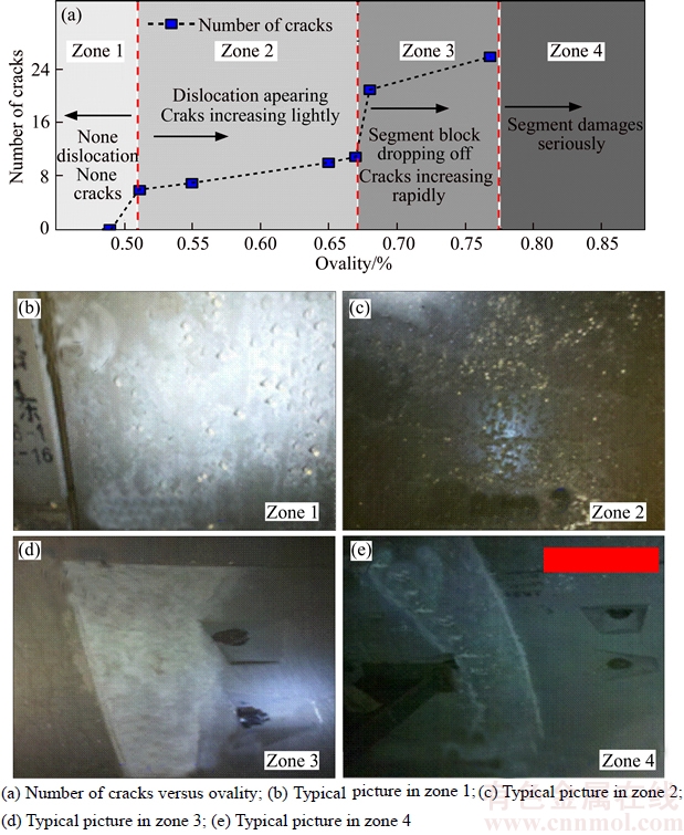
Figure 10 Rest disease performance development as ovality changing:
2) The ovality of the tunnel cross-section could reflect the tunnel diseases degree. In this particular experimental study, no segment crack or drop-off as the ovality is less than 0.5%. The segment dislocation and cracks could be observed when the ovality increases but is less than 0.67%. When the ovality increases from 0.67% to 0.77%, the number of cracks would grow rapidly and even the local segment block drop-off of the segment could be found. Extensive segment block drop-off phenomena could be observed if the ovality is more than 0.77%.
References
[1] JIANG Man, LI Hai-ying, XU Xin-yue, XU Shi-peng, MIAO Jian-rui. Metro passenger flow control with station- to-station cooperation based on stop-skipping and boarding limiting [J]. Journal of Central South University, 2017, 24(1): 236-244. DOI: 10.1007/s11771-017-3424-x.
[2] YANG Xiao-li, LI Zheng-wei, LIU Zheng-an, XIAO Hai-bo. Collapse analysis of tunnel floor in karst area based on Hoek-Brown rock media [J]. Journal of Central South University, 2017, 24(4): 957-966. DOI: 10.1007/s11771- 017-3498-5.
[3] KOYAMA Y. Present status and technology of shield tunneling method in Japan [J]. Tunnelling and Underground Space Technology, 2003, 18(2, 3): 145�C159. DOI: 10.1016/ S0886-7798(03)00040-3.
[4] LEI M, PENG L, SHI C, WANG S. Experimental study on the damage mechanism of tunnel structure suffering from sulfate attack [J]. Tunnelling and Underground Space technology, 2013, 36: 15�C13. DOI: 10.1016/j.tust.2013. 01.007.
[5] MONTERO R, VICTORES J G, MARTINEZ S, JARDON A, BALAGUER C. Past, present and future of robotic tunnel inspection [J]. Automation in Construction, 2015, 59: 99�C112. DOI: 10.1016/j.autcon.2015.02.003.
[6] NI Y Q, YE X W, KO J M. Monitoring-based fatigue reliability assessment of steel bridges: analytical model and application [J]. Journal of Structural Engineering, 2010, 136(12): 1563�C1573. DOI: 10.1061/(ASCE)ST.1943-541X. 0000250.
[7] FENG L, YI X, ZHU D, XIE X, WANG Y. Damage detection of metro tunnel structure through transmissibility function and cross correlation analysis using local excitation and measurement [J]. Mechanical Systems and Signal Processing, 2015, 60�C61: 59�C74. DOI: 10.1016/j.ymssp.2015. 02.007.
[8] SHI C, CAO C, LEI M. An analysis of the ground deformation caused by shield tunnel construction combining an elastic half-space model and stochastic medium theory [J]. KSCE Journal of Civil Engineering, 2017, 21(5): 1933�C1944. DOI: 10.1007/s12205-016-0804-y.
[9] CHEN C S, LIU Y C. A methodology for evaluation and classification of rock mass quality on tunnel engineering [J]. Tunnelling and Underground Space Technology, 2007, 22(4): 377�C387. DOI: 10.1016/j.tust.2006.10.003.
[10] YAZDANI-CHAMZINI A, YAKHCHALI S H. Tunnel boring machine (TBM) selection using fuzzy multicriteria decision making methods [J].Tunnelling and Underground Space Technology,2012, 30: 194�C204. DOI: 10.1016/j.tust. 2012.02.021.
[11] ZHANG W, SUN K, LEI C, ZHANG Y, LI H, SPENCER B F. Fuzzy analytic hierarchy process synthetic evaluation models for the health monitoring of shield tunnels [J]. Computer-Aided Civil and Infrastructure Engineering, 2014, 29(9): 676�C688. DOI: 10.1111/mice.12091.
[12] LUO Y, CHEN J, WANG H, SUN P. Deformation rule and mechanical characteristics of temporary support in soil tunnel constructed by sequential excavation method [J]. KSCE Journal of Civil Engineering, 2017, 21(6): 2439�C2449. DOI: 10.1007/ s12205-016-0978-3.
[13] SHARMA J S, HEFNY A M, ZHAO J, CHAN C W. Effect of large excavation on deformation of adjacent MRT tunnels [J]. Tunnelling and Underground Space Technology, 2011, 16(2): 93�C98. DOI: 10.1016/S0886-7798(01)00033-5.
[14] BHALLA S, YANG Y W, ZHAO J, SOH C K. Structural health monitoring of underground facilities�CTechnological issues and challenges [J]. Tunnelling and Underground Space Technology, 2005, 20(5): 487�C500. DOI: 10.1016/j.tust.2005. 03.003.
[15] HE M C, E SOUSA R L, MULLER A, VARGAS E, SOUSA L R, XIN C. Analysis of excessive deformations in tunnels for safety evaluation [J]. Tunnelling and Underground Space Technology, 2015, 45: 190�C202. DOI: 10.1016/j.tust.2014. 09.006.
[16] WANG Z, SHEN L, XIE J, YAO J. Structure analysis for tunnel longitudinal deformation based on segment dislocation mode [J]. Procedia Engineering, 2012, 31: 487�C491. DOI: 10.1016/j.proeng. 2012.01.1056.
[17] CHEN G Q, HUANG R Q, XU Q, LI T B, ZHU M L. Progressive modelling of the gravity-induced landslide using the local dynamic strength reduction method [J]. Journal of Mountain Science, 2013, 10(4): 532�C540. DOI: 10.1007/ s11629-013-2367-4.
[18] WANG Z, WANG L Z, WANG J C, LI L L. Case study of rehabilitation of a damaged underwater tunnel in the construction phase [J]. Journal of Performance of Constructed Facilities, 2014, 30(1): C4014003. DOI: 10.1061/(ASCE)CF.1943-5509.0000648.
[19] PENG J B, HUANG Q B, HU Z P, WANG M X, LI T, MEN Y M, FAN W. A proposed solution to the ground fissure encountered in urban metro construction in Xi��an, China [J]. Tunnelling and Underground Space Technology, 2017, 61: 12�C25. DOI: 10.1016/j.tust.2016.09.002.
[20] SHIRLAW J N. Observed and calculated pore pressures and deformations induced by an earth balance shield: Discussion [J]. Canadian Geotechnical Journal, 1995, 32(1): 181�C189. DOI: 10.1139/t95-017.
[21] COOPER M L, CHAPMAN D N, ROGERS C D F, CHAN A H C. Movements in the Piccadilly Line tunnels due to the Heathrow Express construction [J]. G��otechnique, 2002, 52(4): 243�C257. DOI: 10.1680/geot.2002.52.4.243.
[22] MAIR R J. Tunnelling and geotechnics: New horizons [J]. G��otechnique, 2008, 58(9): 695�C736. DOI: 10.1680/geot. 2008.58.9. 695.
[23] WONGSAROJ J, SOGA K, MAIR R J. Modelling of long-term ground response to tunnelling under St James's Park, London [J]. G��otechnique, 2007, 57(1): 75�C90. DOI: 10.1680/ssc.41080.0023
[24] XIE X Y, LI P. GPR identification of voids inside concrete based on the support vector machine algorithm [J]. Journal of Geophysics and Engineering, 2013, 10(3): 034002. DOI: 10.1088/1742-2132/10/3/ 034002.
[25] ZHANG D M, MA L X, ZHANG J, HICHER P Y, JUANG C H. Ground and tunnel responses induced by partial leakage in saturated clay with anisotropic permeability [J]. Engineering Geology, 2015, 189: 104�C115. DOI: 10.1016/ j.enggeo.2015.02.005.
[26] SHI C, CAO C, LEI M, PENG L, AI H. Effects of lateral unloading on the mechanical and deformation performance of shield tunnel segment joints [J]. Tunnelling and Underground Space Technology, 2016, 51: 175�C188. DOI: 10.1016/j.tust.2015.10.033.
(Edited by YANG Hua)
���ĵ���
��Բ�ܹ������������ṹ���εĽ��������ۺϷ���
ժҪ���ṹ�����������ṹ������������Ҫ���ݣ�Ȼ�����������ṹ�����������ԡ�����������ص㣬����ͨ������ģ���������Զ���������о��ṹ������ṹ���˵Ĺ�ϵ���Գ�����ij��Բ�ܹ������������¹ʰ���Ϊ���У�ͨ���о��ṹ���Ρ���Ƭ�ѷ졢�ӷ���εȲ����ص㼰������������Բ�ȵ�����ԣ��ۺϷ����������������ͼ���ⷽ�����о������������Բ�������������ָ������ֳ���ǿ������ԣ����������������������̶ȵ���Ҫָ�ꡣ����Բ��С��0.5%�����������Ա���Ϊ������ȫ������״̬�����������Բ�ȳ���0.77%���������������ص��ƻ�״̬���ɹ������ƶܹ�������ع淶���Լ����γ���Ӫ������ά������������Ҫ�����塣
�ؼ��ʣ��ܹ��������������������Σ��ṹ�ƻ�
Foundation item: Projects(BK20150337,BK20140845, BK20140844) supported by the Natural Science Foundation of Jiangsu Province, China; Project(2015Y04) supported by the Transportation Science and Technology Project of Jiangsu Province, China; Project(41504081) supported by the National Natural Science Foundation of China; Projects(2014M561567, 2016T90416) supported by the China Postdoctoral Science Foundation
Received date: 2017-06-05; Accepted date: 2017-12-10
Corresponding author: ZHENG Hu, PhD, Assistant Professor; Tel: +86�C25�C83786962; E-mail: zhenghu@hhu.edu.cn; ORCID: 0000- 0002-9606-9947
Abstract: Health state of shield tunnels is one of the most important parameters for structure maintenance. Usually, the shield tunnel is extremely long in longitude direction and composed by many segments. It is difficult to quantify the relationship between the structure damage state and shield tunnel structure deformation by the model test because of unpredictable effects of different scales between model test and prototype tunnel structure. Here, an in-situ monitoring project was conducted to study the excavation induced shield tunnel structure damage, which could be considered a prototype test on the tunnel deformation. The disaster performance of tunnel leakage, segment crack, segment dislocation and segment block drop-off during longitude deformation and cross-section ovality developments was analyzed. The results indicate that instead of the longitude deformation, the ovality value has the strongest correlation to the rest disease performance, which could be used as the assessment index of the tunnel health. For this tunnel, it is in health state when the ovality is less than 0.5%, and the serious damage could be found when the ovality value is higher than 0.77%. The research results provide valuable reference to shield tunnel health assessment and help complete the standard of shield tunnel construction.
