
Trans. Nonferrous Met. Soc. China 23(2013) 2708-2713
Effects of pin angle and preheating on temperature distribution during friction stir welding operation
R. KEIVANI1, B. BAGHERI2, F. SHARIFI2, M. KETABCHI2, M. ABBASI3
1. Department of Material Engineering, Islamic Azad University (Science and Research Branch), Tehran, Iran;
2. Department of Mining and Metallurgy, Amirkabir University of Technology, Tehran, Iran;
3. Faculty of Engineering, University of Kashan, Kashan, Iran
Received 31 October 2012; accepted 14 January 2013
Abstract:
Friction stir welding (FSW) is applied extensively in industry for joining of nonferrous metals especially aluminum. A three-dimensional model based on finite element analysis was used to study the thermal characteristic of copper C11000 during the FSW process. The model incorporates the mechanical reaction of the tool and thermo-mechanical characteristics of the weld material, while the friction between the material and the probe and the shoulder serves as the heat source. It was observed that the predicted results about the temperature were in good compatibility with the experimental results. Additionally, it was concluded that the numerical method can be simply applied to measuring the temperature of workpiece just beneath the tool. The effects of preheating temperature and pin angle on temperature distribution were also studied numerically. The increase of pin angle enhances the temperature around the weld line, but preheating does not affect temperature distribution along the weld line considerably.
Key words:
friction stir welding; simulation; temperature distribution; pin angle; preheating;
1 Introduction
Friction stir welding (FSW) is a recently emerged solid-state joining technology patented by the Welding Institute (TWI) in 1991 [1]. The process is illustrated schematically in Fig. 1, where a rotating cylindrical shouldered tool plunges into the butted plates and locally plasticizes the region around the separation line during its movement and correspondingly results in the stirring of the material in the nugget and two workpieces are finally joined together [2]. In this process, the heat is originally derived from the friction between the welding tool (including the shoulder and the probe) and the welded material, which causes the welded material to soften at a temperature less than its melting point. The softened material underneath the shoulder is further subjected to extrusion by the tool rotational and transverse movements. It is expected that this process inherently produces a weld with less residual stress and distortion as compared with the fusion welding methods, since no melting of the material occurs during the welding.
Although FSW is a new welding technology, it has been extensively studied in both the academic and industrial communities for most nonferrous alloys especially difficult-to-fusion-weld alloys. Among different issues in regard with FSW, temperature analysis and heat transfer phenomenon during this process have been the point of focus. TANG et al [3] experimentally measured temperature distribution for a workpiece welded by FSW method. ZHANG et al [4] used a thermo-mechanical model to predict the effects of the FSW process parameters on temperatures and material behaviors, and found that both the increase of the rotating speed and the decrease of the welding speed can lead to the increase of the stirring effect of the welding tool, which can improve the friction stir weld quality. GOULD and FENG [5] proposed a simple heat transfer model for predicting the temperature distribution during the FSW process. CHAO and QI [6] developed a moving heat source model in a finite element analysis and simulated the transient temperature, residual stress and residual distortion of the FSW process. ZHANG et al [7] investigated the temperature rises, energy histories and material flows by application of a fully coupled thermo- mechanical finite element model in order to study the effects of thickness during FSW process of AA2024-T3. They concluded that the stirring effect of the welding tool becomes weaker in FSW of thick plates.
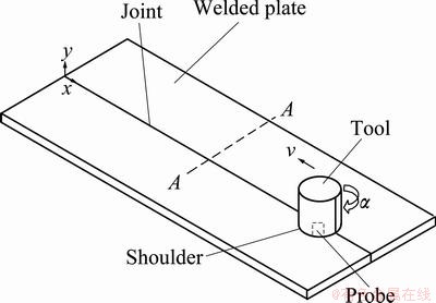
Fig. 1 Schematic illustration of FSW process
Furthermore, COLEGROVE et al [8] and FRIGAARD et al [9] developed three-dimensional heat flow models for predicting temperature fields developed in workpieces during the FSW process. MIDLING [10], RUSSELL and SHEERCLIFF [11] investigated the effect of tool shoulder material and pin tool on heat input during the FSW. Most currently, DONNE et al [12] reported the measured residual stresses in friction stir welds for 2024-T3 and 6013-T6 aluminum alloys. DONG et al [13] carried out a coupled thermo-mechanical analysis of the FSW process using a simplified two-dimensional axisymmetric model. CHAO et al [14] investigated the variations of heat energy and temperature produced by the FSW in both the workpiece and the pin tool. In the current work, the effects of pin angle and preheating on the temperature distribution resulting from FSW method and developed in copper workpieces were investigated.
2 Experimental
2.1 Configuration of tool and workpieces
Copper C11000 workpieces with dimensions of 60 mm��20 mm��3.1 mm were prepared (see Fig. 2). The workpieces were polished and cleaned with acetone on the welding surface and then placed on a backing plate and clamped rigidly by an anvil along the welding direction to prevent lateral movement and lifting. A welding tool made of SKH9 high-speed steel and comprised of a shank, shoulder, and pin was used during the welding. The rotating welding tool was slowly plunged into the workpiece until the shoulder of the welding tool forcibly contacted the upper surface of the material. After a preheating time, the welding tool was forcibly translated along the joint line until the end of the line and finally moved back while the spindle continued to turn. The spindle of this self-designed FSW apparatus can spin with rotational speeds from 400 to 1200 r/min, and the fixture table, driven by a servomotor, can move at speed from 20 to 60 mm/min.
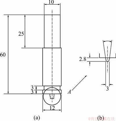
Fig. 2 Dimensions of tool (a) and pin (b) (unit: mm)
A concave part close to the shoulder was specially designed to prevent massive heat loss from the shoulder to the shank of the tool. An inclination angle of 1��, with respect to the welding tool and the normal vector of the workpiece, was set before welding to allow the tool to smoothly traverse the workpiece.
Two welding conditions, ��=800 r/min, v=30 mm/min and ��= 900 r/min, v=50 mm/min, were selected for experiments. During the FSW process, the pin was first plunged into the workpiece with a depth of 2.85 mm. At this moment, the downward force was about 4 kN. After the temperature increased to about 400 ��C, the downward force increased to about 7 kN due to the expansion of the heated metal. Circular rings on the surface of the weld could be clearly observed, and a hole was left after the pin retracted from the workpiece, just as happened in the standard FSW process.
2.2 Layout of thermocouples
Four K-type grounded thermocouples with a sheath diameter of 1 mm were used for temperature measurement. A digital thermometer, TM-747D, was used to connect four thermocouples to a personal computer that contained a data acquisition system installed to record the temperature histories during FSW. Small holes with a diameter of 1 mm were drilled on both sides of the workpiece in order to accommodate the thermocouples. The positions of the thermocouples inside the workpiece are shown in Fig. 3. A small indent at the entrance of each drilled hole was made to prevent the thermocouple from being crushed by the clamp. The sensing head of the thermocouples is approximately 1 mm in length and the holes used to accommodate the thermocouple have a depth of 11 mm. Therefore, the thermocouples were securely embedded in the holes and the temperature could be accurately measured without any external disturbance. The rotation direction and the motion direction of the tool are shown in Fig. 3. As further depicted in Fig. 3, two of the four thermocouples (TC1 and TC3) were placed on the advancing side, and the other two (TC2 and TC4) were placed on the retreating side. The distances between the tips of the thermocouples and the joint line are all 6 mm. This kind of layout was used to measure the temperature histories on the advancing and retreating sides.
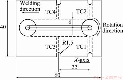
Fig. 3 Layout of thermocouples inside workpiece (unit: mm)
3 FEM model
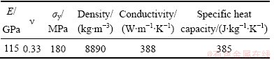
FSW welding process was modeled by Abaqus/ Explicit software to do a thermal analysis. Due to similarity, only half of the tool and workpieces were modeled. Although the workpieces were assumed elastic- plastic, tool was considered rigid. The meshed part as well as tool is shown in Fig. 4. The workpiece consisted of two layers of elements in the thickness direction and 5025 eight-node brick solid elements were totally applied for discretization of workpiece. Different mesh element sizes were assigned to different regions. ALE-Lagrangian adaptive meshing was performed in adaptive mesh domains. Lagrangian adaptive mesh domains were usually used to analyze transient problems with large deformations. The smallest element was in the region of the weld and had the dimensions of 2.64 mm��0.9 mm�� 0.62 mm. The mechanical properties were assumed constant, while the thermal properties were considered temperature-dependant. The thermal-mechanical data related to copper C11000 at room temperature are presented in Table 1.
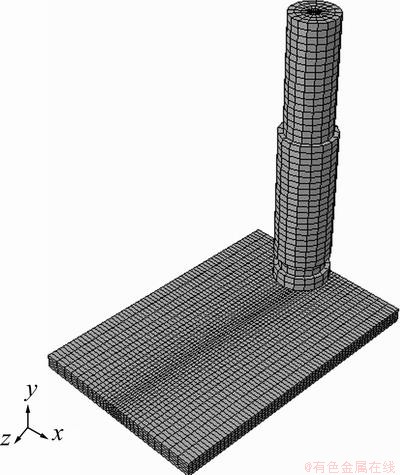
Fig. 4 Meshed workpieces as well as tool utilized during simulation of friction stir welding
Table 1 Mechanical and thermal properties of copper C11000 alloy at room temperature [15]
The temperature history of each node of the FE-model was extracted and transferred to a further FE-model of the joint considering an elasto-plastic behavior of the copper C11000 material. Temperature distribution in workpiece and tool resulting from the simulation of FSW process is schematically shown in Fig. 5.
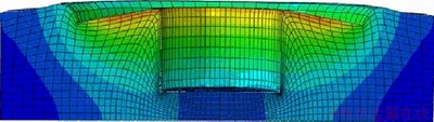
Fig. 5 Temperature distribution in workpiece and tool
4 Discussion and results
4.1 Comparison between experiment and simulation results
Welding conditions were simulated carefully using Abaqus software [16] and temperatures for different nodes were determined. Comparisons between the numerical and experimental temperature histories, based on data recorded by thermocouples (Fig. 3), for the same locations and for two welding conditions are demonstrated in Figs. 6 and 7. Figure 6 relates to ��= 800 r/min and v=30 mm/min welding condition, while for Fig. 7 the welding condition is ��= 900 r/min, v=50 mm/min.
It is shown from these figures that although numerical data do not confirm the experimental results exactly, but the differences are acceptable and especially the maximum temperatures have good compatibility. Additionally, the determination of temperature for locations where experiment is impossible (beneath the pin) and cost and time reductions are some advantages of numerical process over the experimental route.
4.2 Pin angle effect
In Fig. 8 the pin angle is illustrated. The effects of three pin angles, 5, 15 and 25, on temperature distribution were investigated numerically. The resulting distributions are compared with that resulting from non-rotated pin in Fig. 9.
It is observed that the increment of pin angle results in expansion of contours, namely, temperature around the weld position increases. This can be related to the enhancement of contact area between the pin and the workpiece and correspondingly further subjection of softened material underneath the shoulder to extrusion as the tool rotates and traverses. In Fig. 10 the temperature distributions along a path normal to the weld line and for different pin angles are illustrated. It is also shown from this figure that the temperature increases as the pin angle enhances.
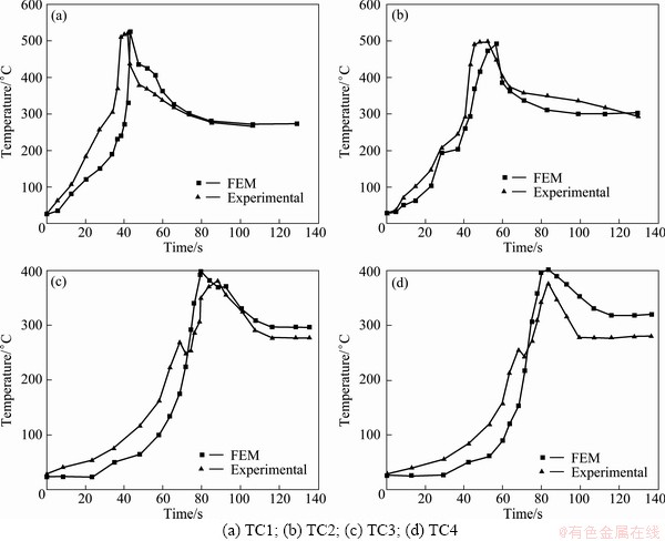
Fig. 6 Comparison between experimental and numerical temperature histories at welding condition of ��=800 r/min, v=30 mm/min
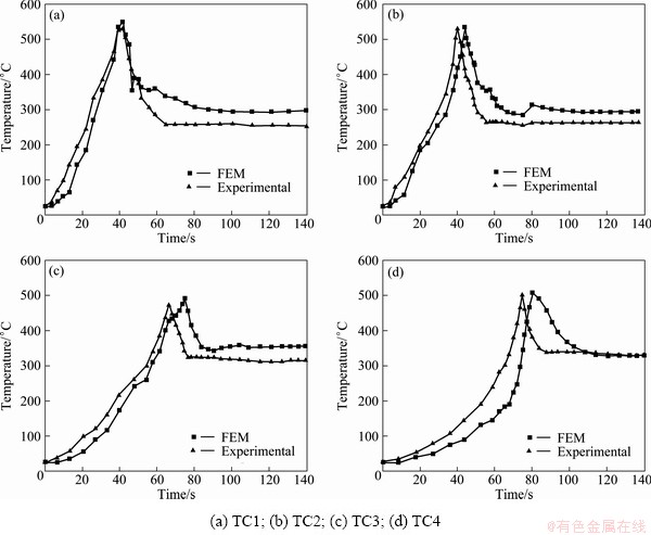
Fig. 7 Comparison between experimental and numerical temperature histories at welding condition of ��= 900 r/min, v=50 mm/min
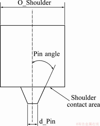
Fig. 8 Schematic design of tool applied in current research
4.3 Preheating effect
The effect of preheating on temperature distribution is shown in Fig. 11. It is observed that as the initial temperature increases, temperature enhances and its curve levels up. It is also observed that while for initial times of welding which relates to plunging step the differences between the curves are large, this differences for times beyond the plunging are negligible. This can be related to the effect of temperature on mechanical properties, especially yield strength. As the initial temperature increases, the yield strength decreases [17], and as a result less forming force is required for deformation during FSW process and consequently less friction stress [18] and heat are generated [7]. While for the workpiece initially heated to low temperature, the generated heat is high, for the workpiece initially heated to high temperature, the produced heat is low. Therefore, the effects of two parameters, namely initial temperature and produced heat during FSW process, for time beyond the plunging step counterbalance each other and the differences among the temperature histories are low.
It should be mentioned that, in the current work, the yield strength is assumed as a temperature-independent variable. It is predicted that regarding the yield strength as temperature-dependant would result in enhanced effect of the latter parameter. Respectively, the differences among the curves, related to different initial temperatures, for time beyond the plunging step would be lower. It can be concluded that although preheating results in high initial temperature of workpieces, but as lower heat is produced during welding process, it does not affect the temperature distribution along the weld line largely.
5 Conclusions
1) As pin angle increases, due to the increment of friction which has the decisive effect on generating heat during FSW process, temperature around the weld line is enhanced.
2) The effect of preheating on temperature distribution along the weld line, due to the effect of generating heat during FSW process, is minor.
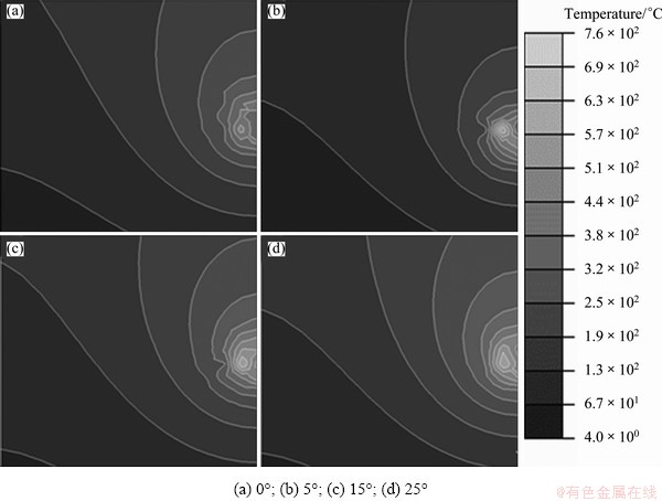
Fig. 9 Thermal distribution for four pin angles
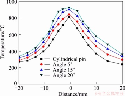
Fig. 10 Temperature distribution along path normal to weld line
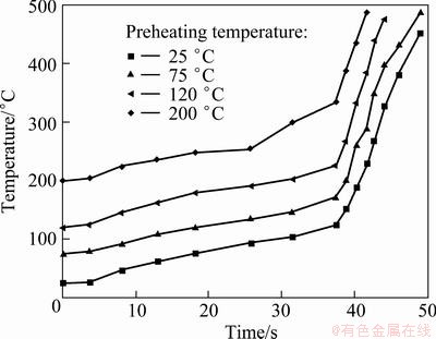
Fig. 11 Temperature histories respected to various preheating temperatures
References
[1] THOMAS W M, NICHOLAS E D, NEED HAM J C, MURCH M G, TEMPLE-SMITH P, DAWES C J. Friction stir butt welding: International patent application No. PCT/GB92/02203, GB patent application No. 9125978.8 [P]. 1991.
[2] CHEN C M, KOVACEVIC R. Finite element modeling of friction stir welding��Thermal and thermo-mechanical analysis [J]. International Journal of Machine Tools & Manufacture, 2003, 43: 1319-1326.
[3] TANG W, GUO X, MCCLURE J C, MURR L E, NUNES A. Heat input and temperature distribution in friction stir welding [J]. Materials Processing & Manufacturing Science, 1999, 37: 163-172.
[4] ZHANG Z, ZHANG H W. Numerical studies on controlling of process parameters in friction stir welding [J]. Journal of Materials Processing Technology, 2009, 209: 241-270.
[5] GOULD J, FENG Z. Heat flow model for friction stir welding of aluminum alloys [J]. Materials Processing and Manufacturing Science, 1998, 7: 185-194.
[6] CHAO Y J, QI X. Thermal and thermo-mechanical modeling of friction stir welding of aluminum alloy 6061-T6 [J]. Materials Processing & Manufacturing Science, 1998, 7: 215-233.
[7] ZHANG Z, CHEN J T, ZHANG Z W, ZHANG H W. Coupled thermo-mechanical model based comparison of friction stir welding processes of AA2024-T3 in different thicknesses [J]. Journal of Materials Sciences, 2011, 46: 5815-5821.
[8] COLEGROVE P, PINTER M, GRAHAM D, MILLER T. Three dimensional flow and thermal modeling of the friction stir welding process [C]//Proceedings of the Second International Symposium on Friction Stir Welding. Gothenburg, Sweden: TWI Ltd, 2000.
[9] FRIGAARD O, GRONG O, MIDLING O T. A process model for friction stir welding of age hardening aluminum alloys [J]. Metallurgical and Materials Transactions A, 2001, 32: 1189�C1200.
[10] MIDLING O T. Effect of tool shoulder material on heat input during friction stir welding [C]//Proceedings of the First International Symposium on Friction Stir Welding. CA, USA, 1999.
[11] RUSSELL M J, SHEERCLIFF H R. Analytic modeling of microstructure development in friction stir welding [C]//Proceedings of the First International Symposium on Friction Stir Welding. CA, USA, 1999.
[12] DONNE C D, LIMA E, WEGENER J, PYZALLA A, BUSLAPS T. Investigations on residual stresses in friction stir welds [C]// Proceedings of the Third International Symposium on Friction Stir Welding [C]. CA, USA, 2001.
[13] DONG P, LU F, HONG J K, CAO Z. Coupled thermo-mechanical analysis of friction stir welding process using simplified models [J]. Science and Technology of Welding and Joining, 2001, 6: 281-287.
[14] CHAO Y J, QI X, TANG W. Heat transfer in friction stir welding experimental and numerical studies [J]. ASME J. Manufactory Science Engineering, 2003, 125: 138-145.
[15] DAVIS J R. Copper and copper alloys [M]. Metals Park, OH: ASM International, 2001.
[16] ABAQUS/6.10 [M]. Providence, RI, USA: Dassault Systems Simulia Corp, 2011.
[17] HOSFORD W F, CADDELL R M. Metal forming- mechanics and metallurgy [J]. 2nd ed. USA: Prentice Hall, 1993.
[18] ZHANG Hong-wu, ZHANG Zhao, BIE Jun, ZHOU Lei, CHEN Jin-tao. Effect of viscosity on material behavior in friction stir welding process [J]. Transactions of Nonferrous Metals Society of China, 2006, 16(5): 1045-1052.
����Ħ�����ӹ����н������Ǻ�Ԥ�ȶ��¶ȷֲ���Ӱ��
R. KEIVANI1, B. BAGHERI2, F. SHARIFI2, M. KETABCHI2, M. ABBASI3
1. Department of Material Engineering, Islamic Azad University (Science and Research Branch), Tehran, Iran;
2. Department of Mining and Metallurgy, Amirkabir University of Technology, Tehran, Iran;
3. Faculty of Engineering, University of Kashan, Kashan, Iran
ժ Ҫ������Ħ����(FSW)���㷺Ӧ���ڹ�ҵ�ϣ�����������ɫ���������������Ͻ𡣲��û�������Ԫ��������άģ���о�FSW������ͭC11000�������ԡ�ģ�Ͱ����˽���ͷ�Ļ�е���úʹ����Ӳ��ϵ������ܣ��Բ��Ϻͽ������Լ����֮���Ħ����Ϊ��Դ������������¶ȵ�Ԥ������ʵ�����������õ�һ���ԡ����⣬��ֵģ�ⷽ�����Լ�Ӧ���ڲ�������ͷ�·��������¶ȡ��о���Ԥ���¶Ⱥͽ������Ƕ��¶ȷֲ���Ӱ�졣�������ǵ����ӿ���ߺ�����Χ���¶ȣ���Ԥ�Ȳ���Ӱ�캸����Χ���¶ȷֲ���
�ؼ��ʣ�����Ħ������ģ�⣻�¶ȷֲ����������ǣ�Ԥ��
(Edited by Xiang-qun LI)
Corresponding author: M. ABBASI; Tel: +98-21-64542949; Fax: +98-21-66405846; E-mail: m.abbasi@aut.ac.ir
DOI: 10.1016/S1003-6326(13)62788-0
Abstract: Friction stir welding (FSW) is applied extensively in industry for joining of nonferrous metals especially aluminum. A three-dimensional model based on finite element analysis was used to study the thermal characteristic of copper C11000 during the FSW process. The model incorporates the mechanical reaction of the tool and thermo-mechanical characteristics of the weld material, while the friction between the material and the probe and the shoulder serves as the heat source. It was observed that the predicted results about the temperature were in good compatibility with the experimental results. Additionally, it was concluded that the numerical method can be simply applied to measuring the temperature of workpiece just beneath the tool. The effects of preheating temperature and pin angle on temperature distribution were also studied numerically. The increase of pin angle enhances the temperature around the weld line, but preheating does not affect temperature distribution along the weld line considerably.
