

Solution of rectangular bar forging with bulging of
sides by strain rate vector inner-product
WANG Lei1, JIN Wen-zhong2, ZHAO De-wen3, LIU Xiang-hua3
1. School of Materials Science and Engineering, Shanghai University, Shanghai 200072, China;
2. Shanghai Shenhua Acoustics Equipment Co. Ltd., Shanghai 201709, China;
3. State Key Laboratory of Rolling and Automation, Northeastern University, Shenyang 110004, China
Received 19 July 2010; accepted 17 November 2010
Abstract:
A new linear integration solution was constructed for determining the total pressure developed during forging of a rectangular bar with flat tools. The effective strain rate for rectangular bar forging with bulging was expressed in terms of four-dimensional strain rate vector. The inner-product of the vector was termwise integrated and summed. The integral mean value theorem was applied to determining the ratio of the strain rate components and the values of direction cosine of the vector and then an analytical solution of stress effective factor was obtained. The compression experiments of pure lead bar were performed to test the accuracy of the solution. The optimized results of total pressure by golden section search were compared with those of the indicator readings of the testing machine. It indicates that the optimized total pressures are 2.60%-10.14% higher than those measured. The solution is available and still an upper-bound solution.
Key words:
rectangular bar forging; bulging; strain rate vector; inner-product; golden section search;
1 Introduction
Forging a bar with flat tools is one of the simplest and most widely used processes in industry. However, its analysis is far from being simple. Hence a few approximate solutions have come forth, such as the upper bound [1-2], the lower bound [3-4] and slip line [5]. With the development of computers, numerical methods have been used to simulate the forging process [6-7]. ZHANG and XIE [8] and KANG et al [9] simulated forging process by FEM. GRASS et al [10] and GAO et al [11] used 3D-FEM simulation. And UBET has been successfully applied to solving the forging process by the authors [12-13]. These methods can all be applied to solving the forging, but just the numeric results are obtained.
In this work, the method so called inner-product of strain rate vector [14-15] is constructed and first applied to solving the bar forging and the analytic result of stress effective factor is obtained.
2 Velocity field
The origin of Cartesian coordinates is taken as the geometric centre of the body. The axes X, Y and Z divide the deforming zone into eight identical regions. So only the eighth is considered (Fig. 1). For any point with coordinates x, y and z, the velocity field is given by [1]
![]() (1)
(1)
![]() ,
, ![]() ,
,
![]() (2)
(2)
where vx, vy, vz are components of particle velocity in Cartesian coordinate system; v0 is velocity of the top die; A is a constant to be determined by optimization on energy dissipation.
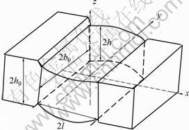
Fig. 1 Rectangular bar subjected to compression
The velocity field satisfies the boundary conditions:
at x=0, ![]() ; at x=l, vy=0. and the incompressibility condition, i.e.
; at x=l, vy=0. and the incompressibility condition, i.e.
![]() (3)
(3)
where
![]() ,
, ![]() ,
,
![]() ,
, ![]() ,
,
![]() (4)
(4)
where ![]() is the component of strain rate tensor.
is the component of strain rate tensor.
From the mean value theorem of integral and Eq.(4), mean values of the strain rate can be obtained as follows:
![]()
![]()
![]() ,
,
![]() ,
,
![]() ,
,
![]() (5)
(5)
It can be seen that Eq. (5) still satisfies
![]()
With the help of Eq. (2), the ratio of mean velocity can also be calculated as
![]() ,
, ![]() ,
,
![]() (6)
(6)
3 Total power
3.1 Internal deformation power
The integrand of plastic power is expressed by
![]()
![]()

![]()
![]()


![]()

![]()
![]()
![]()
![]()
![]() (7)
(7)
where ![]() is strain rate vector;
is strain rate vector; ![]() is unit vector;
is unit vector; ![]() is direction cosines of unit vector; and
is direction cosines of unit vector; and ![]() is termwise integration of the strain rate vector.
is termwise integration of the strain rate vector.
From Eq. (7), the direction cosines are
 (8)
(8)
The first termwise integration of strain rate vector inner product I1 is
![]()


Substituting Eqs. (4) and (5) into above integral, it follows that


With the same procedure, the other termwise integration results are


Substituting the results of I1, I2, I3 and I4 into Eq. (7) and rearranging yields
![]()
![]() (9)
(9)
3.2 Friction power
Let ![]() ,
, ![]() , the friction power is
, the friction power is
![]()

where ��f is the shear along surface of velocity discontinuity; k is von Mises�� constant of yield criterion; ��s is effective flow stress; ![]() is the velocity discontinuity.
is the velocity discontinuity.
Substituting ![]() of Eq. (6) for
of Eq. (6) for ![]() in above integrand, and integrating leads to
in above integrand, and integrating leads to
![]() (10)
(10)
3.3 Shear power
From Eq. (2), the velocity discontinuity at interface between deformation and external zones can be written as
![]()
So shear power becomes
![]()
![]() (11)
(11)
3.4 Stress effective factor and minimization
Let applied power ![]() , and substitute Eqs. (9), (10) and (11) into it, then rearranging leads to
, and substitute Eqs. (9), (10) and (11) into it, then rearranging leads to
![]()
![]()
![]() (12)
(12)
where n�� is stress effective factor.
It is obviously that the stress effective factor n�� is a function of A, m, b0/h and l/h, also is a analytical solution. The optimum values of A and n�� by the golden section search are shown in Fig. 2.
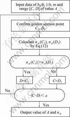
Fig. 2 Flow chart of golden section search
4 Experiment
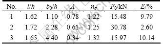
In order to validate the solution in this work, the compression test was performed on 200 kN universal material testing machine. The dimensions of the three groups of pure lead specimens and the indicator readings of the machine during compressing are listed in Table 1. The ram speed was 30 mm/min.
Table 1 Specimen dimension and measured force

Taking No.1 specimen as an example, the calculating procedure is given in detail as follows.
From Table 1, l/h=1.62, b0/h=1.10, and m=0.2 (for quenched steel and lapped face). Then inputting the values of l/h, b0/h, and m into Eq. (12) and optimizing by flow chart in Fig. 2, the optimum result becomes: A=0.78, n��=1.22.
From Table 1, the strain and the strain rate for No.1 specimen are![]() ;
; ![]()
![]() s-1.
s-1.
According to the values of �� and ![]() , the yield stress for pure lead is ��s=20.05 MPa [16]. Then the total compression force for No.1 sample is
, the yield stress for pure lead is ��s=20.05 MPa [16]. Then the total compression force for No.1 sample is
![]() kN
kN
Comparing it with the measured value Fm in Table 1, the relative error can (E) be expressed as
![]()
With the same procedure, the optimized results of No. 2 and 3 specimens can also be obtained and listed in Table 2.
Table 2 Optimized results for three groups of specimens
From the results we can know that the relative errors between the optimized results and the measured ones are from 2.60% to 10.14%, all admitted in engineering.
5 Discussion
In order to examine the characteristics of the present solution, the optimum values of A and n�� were optimized for the values of l/h varying from 0.5 to 5.5 and b0/h equal to 1.10, 2.28 and 4.40 and m from 0.2 to 1.0. The value of parameter A signifies the extent of bulging. From Fig. 3 it can be seen that bulging parameter A increases with increasing l/h or decreasing b0/h for a given m. Figure 4 shows that n�� increases as m increases for given values of b0/h and l/h, but always exists a minimum value of n�� in each curve.
Fig. 5 shows that the value of n�� increases with increasing b0/h and m for a given l/h.
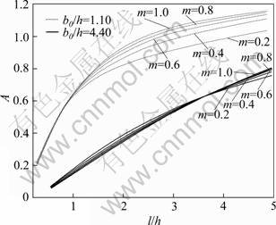
Fig. 3 Influence of l/h and b0/h on optimum values of A
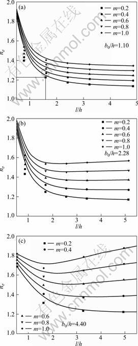
Fig. 4 Influence of l/h, b0/h and m on n�� for optimum values of A
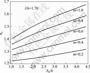
Fig. 5 Influence of b0/h on n�� for given l/h
6 Conclusions
1) With the help of strain rate vector inner-product, the analytical solution of stress effective factor n�� for rectangular bar forging is obtained. And n�� is a function of A, m, b0/h and l/h.
2) Through pure lead compression test, the optimized results by above solution are 2.60%-10.14% higher than those measured.
3) The relationship among A, l/h, b0/h and m can be described. Bulging parameter A increases with increasing l/h or decreasing b0/h for a given m.
References
[1] SAGAR R, JUNEJA B L. An upper bound solution for flat tool forging taking into account the bulging of sides [J]. International Journal of Machine Tool Design and Research, 1979, 19(4): 253-258.
[2] WANG Zhen-fan. Upper bound solution and its application in metal forming [M]. Shenyang: Northeast University of Technology Press, 1991: 200-203. (in Chinese)
[3] HASHMI M S J. A lower bound solution for the plane strain extrusion forging process [J]. Mathematical and Computer Modelling, 1988, 11: 1183-1188.
[7] PITTMAN J F T. Numerical analysis of forming processes [M]. New York: John Wiley and Sons, 1984: 32-33.
[11] GAO Tao, YANG He, LIU Yu-li. Backward tracing simulation of precision forging process for blade based on 3D FEM [J]. Transactions of Nonferrous Metals Society of China, 2006, 36(S2): 639-644.
[14] ZHAO De-wen. Mathematical solutions of continuum forming force [M]. Shenyang: Northeastern University Press, 2003: 421-425. (in Chinese)
[15] ZHAO De-wen, JIN Wen-zhong, WANG Lei, LIU Xiang-hua. Inner-product of strain rate vector through direction cosine in coordinates for disk forging [J]. Transactions of Nonferrous Metals Society of China, 2006, 16(6): 1320-1324.
Ӧ��ʸ���ڻ����������εľ�������ѹ
�� ��1, ������2, �Ե���3, ���3
1. �Ϻ���ѧ ���Ͽ�ѧ�빤��ѧԺ���Ϻ� 200072��
2. �Ϻ��껪��ѧװ������˾���Ϻ� 201709��
3. ������ѧ ���Ƽ����������Զ��������ص�ʵ���ң����� 110004
ժ Ҫ�����һ���µ����Ի����ַ����������ƽ��ͷѹ������˵ľ��μ����ڶ�ѹ�����У���ͷû�и����������������ҹ����IJ���ͨ�����β������Ρ�Ӧ�ø÷����õ���ƽ����ѹ����ͬʱ�����Ĺ����н��������м��裺�����빤���Ħ����Ϊ�����������Ǹ�-���Բ��ϣ���ѹ���ڵ��ٶ��½��еġ�Ȼ��ͨ����Ǧ�Ķ�ѹʵ�飬���ɻƽ�ָ�õ����Ż�������������ʵ��ֵ���бȽϣ���������Ż�ֵ��ʵ��ֵ��2.60%-10.14%�����ڹ����϶��������ġ�
�ؼ��ʣ���������ѹ�����Σ�Ӧ������ʸ�����ڻ����ƽ�ָ
(Edited by LI Xiang-qun)
Foundation item: Project (51074052) supported by the National Natural Science Foundation of China; Project (20100470676) supported by the China Postdoctoral Science Foundation
Corresponding author: ZHAO De-wen; Tel: +86-24-83686423; E-mail: zhaodw@ral.neu.edu.cn
DOI: 10.1016/S1003-6326(11)60867-4
