
Trans. Nonferrous Met. Soc. China 23(2013) 2446-2453
Characterization of microstructural length scales in directionally solidified Sn-36%Ni peritectic alloy
Peng PENG, Xin-zhong LI, Yan-qing SU, Dong-mei LIU, Jing-jie GUO, Heng-zhi FU
School of Material Science and Engineering, Harbin Institute of Technology, Harbin 150001, China
Received 16 July 2012; accepted 5 December 2012
Abstract:
Sn-36%Ni peritectic alloys were directionally solidified at different growth rates under a constant temperature gradient (20 K/mm), the dependences of microstructural characteristic length scales on the growth rate were investigated. Experimental results are presented, including primary and higher order dendrite arm spacings ��1, ��2, ��3 and dendrite tip radius R of primary Ni3Sn2 phase. Comparisons between the theoretical predictions and the experimental results show that, for the primary dendrites, ��1=335.882v-0.21, which is in agreement with the Kurz-Fisher model; for the secondary dendrites, ��2=44.957v-0.277, which is consistent with the Bouchard-Kirkaldy model; for the tertiary dendrites, ��3=40.512v-0.274; for the dendrite tip radius, R=22.7v-0.36. The experimental results also show that the ��1/��2 changes greatly with increasing growth rate while the ��1/��3 has no significant change, indicating that tertiary dendrite arms have a more similar growth characteristics to primary dendrites compared with secondary dendrites. The ��1/R ranges from 2 to 2.3 with the increase of growth rate.
Key words:
Sn-Ni alloy; directional solidification; dendrite arm spacing; dendrite tip radius;
1 Introduction
The dendrite solidification microstructure has been observed in many alloys [1-4]. It is generally described by suitable length scales, such as primary and higher order dendrite arm spacing (��1, ��2, ��3) and dendrite tip radius (R) which have been characterized as functions of alloy tip growth rate, solute concentration and temperature gradient [5-7]. In peritectic solidification, dendrites of primary phase often grow in a matrix of peritectic phase over a wide range of growth rates, thus, investigation on the dependence of microstructural characteristic length scales on solidification processing parameters such as growth rate in peritectic alloys is expected.
The primary dendrite arm spacing (��1) and secondary dendrite arm spacing (��2) have been studied in many peritectic alloys such as Pb-Bi [8], Cu-Zn [9]. MA et al [9] also proposed that the values of ��v1/2 for peritectics are generally two orders of magnitude higher than those for eutectics. They also held that the arm coarsening for primary phase should be suppressed by the formation of peritectic phase surrounding the primary phase, which has been demonstrated in some peritectic alloys [8]. However, the tertiary dendrite arm spacing and dendrite tip radius have never been discussed in these investigations. Neither have the relations between these characteristic length scales been concerned up to now in peritectic solidification process, which is insufficient to describe the dependence of solidification condition on the characteristic length scales in peritectic alloys.
In the present work, Sn-Ni peritectic alloy which has attracted wide attention due to its extensive application of developing lead-free solders [10] and anode material for lithium ion battery with better cyclic performance and higher capacity [11] was chosen. Microstructural characteristic length scales of primary Ni3Sn2 phase were measured and compared with theoretical predictions in directionally solidified Sn-36%Ni (mole fraction) alloy at extensive growth rates (2-200 ��m/s). First, these characteristic length scales of the primary Ni3Sn2 phase in directionally solidified Sn-36%Ni alloys were measured and compared with the theoretical predictions; then, relations among these characteristic length scales were investigated and compared with other alloys.
2 Experimental
2.1 Sample production process
The Sn-36%Ni alloy was induction melted from pure Ni and Sn (99.9%). As-cast rods of 3 mm in diameter and 110 mm in length were machined from the ingot by a spark machining. Experiments consisting of melting followed by directional solidification were carried out in a Bridgman-type furnace which consists of a resistance furnace, a water cooled liquid metal bath filled with liquid Ga-In-Sn alloy, and an adiabatic zone which is located between the heater and the cooler, as previously described. For each experiment, the furnace was heated to 1250 ��C to melt the alloy, and then was held for 30 min to homogenize the melt. Solidification of Sn-36%Ni peritectic alloy was carried out at different growth rates (2, 5, 10, 15, 20, 40 and 200 ��m/s) under a constant temperature gradient (20 K/mm) in the Bridgman-type furnace. After a predetermined distance of 30 mm reached, the samples were quenched into liquid Ga-In-Sn alloy quickly to preserve the solid/liquid interface. According to results by SMITH et al [12], the length of the initial transient zone can be obtained using l=4D/vk, where D is the solute diffusion coefficient in liquid, v is the pulling rate and k is the solute distribution coefficient. In the present work, for the lowest growth rate 2 ��m/s, the length of the initial transient zone is 15 mm which is much smaller than 30 mm, thus the growth distance of 30 mm is long enough to achieve the steady-state.
2.2 Measurement of temperature gradient and microstructural length scales
The samples were placed into 99.99% pure alumina crucibles of 4/5.5 mm in inner/out diameter and 150 mm in length. The temperature gradient was measured by PtRh30- PtRh6 thermocouples that were placed near the outside surface of the alumina crucible. One thermocouple was placed 5 mm from the bottom of the sample where was near the solid/liquid interface. The other was placed 15 mm from the bottom of the sample where was the liquid region. The temperature gradient close to the solid/liquid interface was measured to be 20 K/mm. The temperature gradient can be changed by changing the temperature of the specimen. To keep the temperature gradient constant during directional solidification, the temperatures of the cooler and the hotter part of the furnace were kept constant by an automatic temperature controlling system.
The phases in the samples were identified by a Rigaku D/max-RB X-ray diffractometer with mono- chromatic Cu K�� radiation. Both optical and scanning electron microscopy (SEM) were used to characterize the microstructure of the specimens after polishing and etching by a solution of 10 g FeCl3+20 mL HCl+180 mL H2O. Backscattered electron imaging (BSE) was used to identify the phases. Primary dendrite arm spacing was measured by  described by JACOBI and SCHWERDTFEGER [13], where A is the area of the transverse section and N is the number of the primary dendrites counted. The secondary dendrite arm spacing (��2) was measured by averaging the distance between adjacent side branches on the longitudinal section of a primary arm. The tertiary value (��3) was measured in longitudinal section of samples. The primary dendrite tip radius (R) was measured by comparing the unperturbed tip region to a series of parabolas of known curvatures as described by SOMBOONSUK et al [6]. The procedure involved projecting a greatly enlarged tip image from the photographic negative onto the standard parabolas and adjusting the magnification until a best fit was obtained. At least 15 readings were taken for each sample and the values of these characteristic length scales were the mean of these measured values.
3 Results
3.1 Microstructure of directionally solidified Sn-36%Ni alloy
Equilibrium solidification process of Sn-36%Ni alloy [14] begins at tL=1040 ��C with a precipitation of primary Ni3Sn2 phase: L��Ni3Sn2, followed by a peritectic reaction at tP=798 ��C: L+Ni3Sn2��Ni3Sn4, and the remaining liquid will solidify through the eutectic reaction at tE=231.15 ��C: L��Ni3Sn4+Sn. Backscattered electron (BSE) images of microstructure of directionally solidified Sn-36%Ni peritectic alloy at different growth rates (2-200 ��m/s) are shown in Fig. 1. The quenched liquid is behind the solid/liquid interface. Ahead of the interface is the mushy zone, where the solid and the liquid coexist.
As shown in Fig. 2, according to the EDX results of the solubility of components in each phase, the dark gray, bright gray and white phases correspond to the primary Ni3Sn2 phase, peritectic Ni3Sn4 phase and (Ni3Sn4+Sn) eutectic, respectively. The compositions of the two phases comprising the eutectic are 56.23% and 99.67% Sn, respectively, which means that the two phases are Ni3Sn4 and Sn. In the present work, developed dendrite morphology forms, as shown in Fig. 3(a); primary and higher order dendrites can be observed; tertiary dendrite arms initiating from secondary dendrite arms are clearly illustrated in Fig. 3(b).
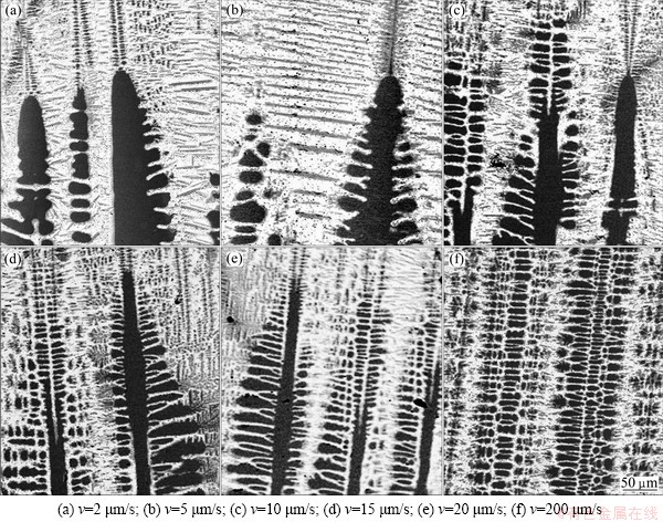
Fig. 1 SEM micrographs showing evolution of morphology of solid/liquid interface in directionally solidified Sn-36%Ni peritectic alloy
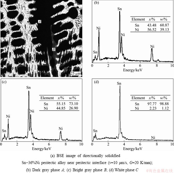
Fig. 2 Chemical composition analysis of Sn-36%Ni peritectic alloy by SEM-EDX

Fig. 3 Dendritic morphology in directionally solidified Sn-36%Ni peritectic alloy at growth rate of v=15 ��m/s
3.2 Primary dendrite arm spacing ��1
Studies characterizing the variation of primary dendrite arm spacing with alloy composition, solidification rate (v), and temperature gradient (G) in the liquid involving solidification both in steady-state heat flow [15-18] and in unsteady-state regime [7] have been reported.
HUNT [15] derived a model for the primary spacing ��1:
 (1)
(1)
where k is the equilibrium distribution coefficient, D is the diffusion coefficient in the liquid, �� is the Gibbs-Thomson coefficient, G is the temperature gradient and ��T0 is the equilibrium solidification temperature range given by
 (2)
(2)
where m is the liquidus slope and C0 is the initial alloy composition.
Later, using a simplified solution to the wavelength instability, KURZ and FISHER [5] gave
 (3)
(3)
A good approximation for ��1 was derived by KURZ et al [16,17] as
 (4)
(4)
HUNT and LU [18] proposed an analytical expression for corresponding cellular spacing from their numerical predictions of the lower limit of stable primary dendritic/cellular spacing, namely:
 (5)
(5)
BOUCHARD and KIRKALDY [7] derived a spacing formula for steady-state solidification and have proved its utility in the unsteady regime. The formula is given by
 (6)
(6)
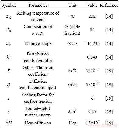
The physical parameters used in calculations of the Sn-Ni peritectic system are illustrated in Table 1.
Table 1 Physical parameters for Sn-Ni system
The predictions of these models are compared with the experimental results shown in Fig. 4. Variation of ��1 versus v is essentially linear on the logarithmic scale. It can be found from Fig. 4 that the data form straight lines and the models discussed above show different constancies: the Hunt model (Eq. (1)) and the Kurz-Fisher model (Eq. (3)) show constancy of ��1v1/4 for a given C0 whereas the Kurz-Giovanola-Trivedi (Eq. (4)) and Hunt-Lu (Eq. (5)) models indicate constancy of ��1v1/2 and ��1v0.59, for a given C0, respectively. The Kurz-Fisher model exhibits excellent agreement with experimental data for Sn-36%Ni alloy. Our results show that ��1=335.882v-0.21. Both the Hunt-Lu model and Kurz-Giovanola-Trivedi model predict large deviations from our experimental results. It can be found that the exponent value of growth rate (0.21) in the present work makes a large difference compared with the eutectics which have been reported (close to 0.5) [20,21].
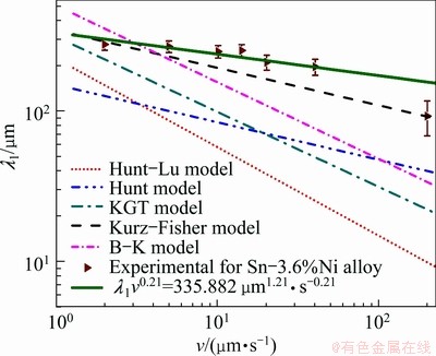
Fig. 4 Variation of primary dendrite arm spacing ��1 with growth rate v under constant temperature gradient (G = 20 K/mm)
3.3 Secondary dendrite arm spacing ��2
KATTAMIS and FLEMINGS [22] predicted that the secondary dendrite arm spacing ��2 is proportional to the cube root of solidification time (tf), and gave
 (7)
(7)
 (8)
(8)
where  is the maximum concentration in the liquid. In the case of directional solidification, the local solidification time is given by tf=��T/Gv, where G is the temperature gradient, v is the growth rate, and ��T is the non-equilibrium solidification range.
LANGER and  -KRUMBHAAR [23] predicted a scaling law between secondary dendrite arm spacing ��2 and the dendrite tip radius R as ��1/R=2. With this scaling law, the variation in ��2 under small Peclet number conditions given by TRIVEDI and SOMBOONSUK [24] is
 (9)
(9)
For secondary dendrite arm spacing, BOUCHARD and KIRKALDY [7] also derived a formula:
 (10)
(10)
The predictions of these models are compared with the experimental results shown in Fig. 5. The experimental results show that ��2=44.957v-0.277 and it can be observed from Fig. 5 that the Bouchard-Kirkaldy (B-K) model exhibits excellent agreement with the experimental data. The commonly accepted Kurz-Fisher (K-F) model predicts larger deviation from our experimental results which can be attributed to the retard of coarsening of the secondary dendrite arms by peritectic reaction and transformation [7].
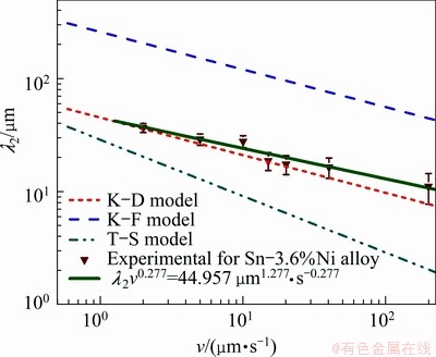
Fig. 5 Variation of secondary dendrite arm spacing ��2 with growth rate v under constant temperature gradient (G=20 K/mm)
3.4 Tertiary dendrite arm spacing ��3
Dendrites can adjust their primary spacing during growth without difficulty. If the primary spacing is too large, a tertiary arm initiating from the secondary branches will catch up to the growing primary tips and become one of them [25]. Investigations on tertiary dendrite arms are relatively scarce in the literature. They are more commonly mentioned on steady-state growth experiments where they are observed to grow past initiating secondary branches and go on to become primary arms [26]. GRUGEL [27] carried out experiments in directional steady-state growth of Al�CSi alloys, and from the spacing measurements suggested a power law correlating ��3 with local solidification time (tf):
 (11)
(11)
Based on the experimental examination of both Sn-Pb and Al-Cu alloys,  et al [28] proposed a 0.55 power law to characterize the variation of tertiary spacing with the cooling:
 (12)
(12)
where k is a coefficient which can be determined by regression analysis. The predictions of these models are compared with the experimental results in Fig. 6. By linear regression analysis we can obtain that ��3=40.512v-0.274. And it can be found from Fig. 6 that the 0.55 model (��3=4.23tf0.55) exhibits reasonable agreement with the experimental data at lower growth rates but predicts large deviations from the experimental results when v exceeds 20 ��m/s.

Fig. 6 Variation of tertiary dendrite arm spacing ��3 with growth rate v under constant temperature gradient (G = 20 K/mm)
3.5 Dendrite tip radius R
Numerous studies have been carried out on the dendrite tip radius R. HUNT [15] proposed that:
 (13)
(13)
according to the Kurz and Fisher model [5]:
 (14)
(14)
and according to the Trivedi model [24]:
 (15)
(15)
where L is a constant which depends on the harmonic of perturbation. From the research of TRIVEDI, L=l/[2(l+1)(l+2)], in which the l=6 harmonic is operative for dendrite growth.
It can be seen from Eqs. (13)�C(15) that the theoretical models for dendrite tip radius, R, are very similar and the differences among them are a constant only. The predictions of these models are compared with the experimental results shown in Fig. 7. It can be obtained through linear regression analysis that R=22.7v-0.36. It can be observed from Fig. 7 that the Trivedi model exhibits excellent agreement with the experimental data at low growth rates while the Kurz-Fisher model predicts small deviations from our experimental results when the growth rate v exceeds 20 ��m/s.

Fig. 7 Variation of dendrite tip radius R with growth rate v under constant temperature gradient (G=20 K/mm)
3.6 Relations between characteristic length scales
The ��1/��2 has been used to estimate the permeability of the mushy zone, but only limited information is available in the literature about this ratio. CICUTTI and BOERI [29] developed an analytical model to estimate the ��1/��2 and a roughly constant value was obtained for (��1/��2):(��1/��2)��2.6. This is consistent with the values ranging from 2 to 4 suggested by WOLF [30]. But it can be observed from our experimental results in Fig. 8(a) that the ��1/��2 is not constant but range from 7.6 to 14.1 with the increase of growth rate. This means that the primary dendrite arm spacing ��1 decreases more slowly than the secondary dendrite arm spacing ��2 when the growth rate increases. This is in consistent with our discussion in sections 3.2 and 3.3 that ��1 and ��2 exhibit power law of 1/4 and 1/3, respectively. For ��2 exhibits much more dependence on interface curvature which has little effect on ��1, and the coarsening mechanism also has effect on ��2, thus the variations of ��1 and ��2 exhibit different tendencies.
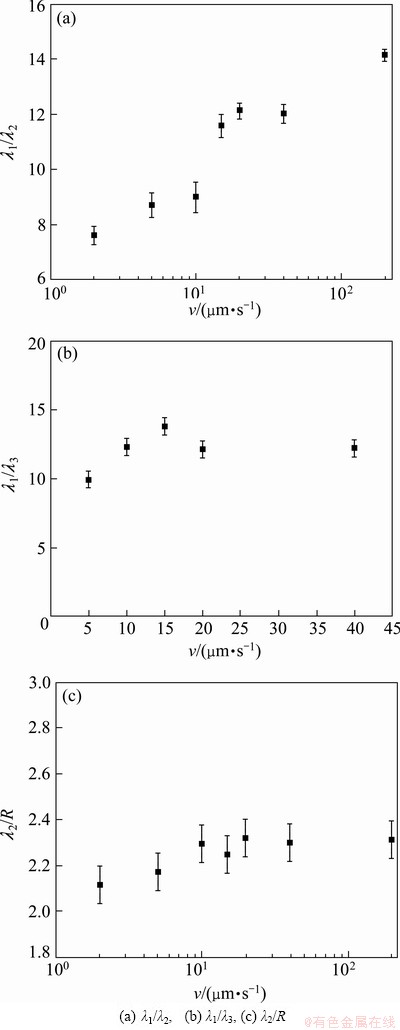
Fig. 8 Relation between characteristic length scales
The values of ��1/��3 for Al-Cu, Pb-15%Sn (mass fraction) and Pb-30%Sn (mass fraction) alloys are 3.4, 5, 6, respectively [28]. The values of this ratio in this study are shown in Fig. 8(b), and it can be found that ��1/��3 does not remain constant but reaches its maximum at the growth rate of 15 ��m/s. This can be attributed to the initiation of tertiary dendrite arm which results from adjustment of primary dendrite arms. At lower growth rate, in order to reduce the undercooling between primary dendrite arms, tertiary dendrite arms originate from secondary dendrite arms. Since ��2 decreases faster than ��1, ��3 also decreases faster than ��1. But when the growth rate is above a threshold, according to the branching mechanism of primary dendrite arm, the interdendritic space for primary dendrite arm branching is limited, thus ��1/��3 has no significant change. And from this it can be found that despite the fact that tertiary arms develop from secondary branches, they have a growth characteristic similar to the primary dendrite arms.
A numerical analysis of the wavelength of instabilities along the sides of a dendrite was carried out by LANGER and -KRUMBHAAR [23] and they predicted a scaling law as ��2/R��2. The results of numerous studies showed that although in most cases the ��2/R might be constant, its value is different in different alloy systems, and ranges from 2 [24] to 4.86 [31]. It can be found from our experimental results in Fig. 8(c) that ��2/R is not constant but ranges from 2 to 2.3 with the increase of growth rate.
4 Conclusions
1) For a given C0 of Sn�CNi peritectic alloy, the values of ��1, ��2, ��3 and dendrite tip radius R decrease as the growth rate increases. The relations between the microstructural parameters and the solidification parameters were obtained by linear regression analysis as: ��1=335.882v-0.21, ��2=44.957v-0.277, ��3= 40.512v-0.274, R=22.7v-0.36.
2) The ��1/��2 is not constant but ranges from 7.6 to 14.1 with the increase of growth rate; the ��1/��3 does not remain constant but reaches its maximum at the growth rate of 15 ��m/s; the ��2/R ranges from 2 to 2.3 with the increase of growth rate.
3) It can be observed from the variation of ��1/��2 and ��2/R with growth rate that the secondary dendrite arm spacing ��2 is more sensitive to solidification parameters compared with primary dendrite arm spacing ��1. The variation of ��1/��3 shows that tertiary dendrite arm has a similar growth characteristic to primary dendrite arm.
References
[1] ZHOU J X, WANG J, WANG J, YANG Y S. Effect of RE and Sr additions on dendrite growth and phase precipitation in AZ91D [J]. Transactions of Nonferrous Metals Society of China, 2010, 20: s331-s335.
[2] HU X W, LI S M, GAO S F, LIU L, FU H Z. Effect of melt convection on primary dendrite arm spacing in directionally solidified Pb-26%Bi hypo-peritectic alloys [J]. Transactions of Nonferrous Metals Society of China, 2011, 21: 65-71.
[3] LIU G H, LI X Z, SU Y Q, CHEN R R,GUO J J, FU H Z. Microstructure and microsegregation in directionally solidified Ti-46Al-8Nb alloys [J]. Transactions of Nonferrous Metals Society of China, 2012, 22: 1342-1349.
[4] WANG Z P, WANG J W, ZHU C S, FENG L, XIAO R Z. Phase-field simulation of forced flow effect on dendritic growth perpendicular to flow [J]. Transactions of Nonferrous Metals Society of China, 2011, 21: 612-617.
[5] Kurz W, Fisher J D. Dendrite growth at the limit of stability: Tip radius and spacing [J]. Acta Materialia, 1981, 29: 11-20.
[6] Somboonsuk K, Mason J T, Trivedi R. Interdendritic spacing: Part I. Experimental studies [J]. Metallurgical and Materials Transactions A, 1984, 15: 967-976.
[7] Bouchard D, Kirkaldy J S. Prediction of dendrite arm spacings in unsteady- and steady-state heat flow of unidirectionally solidified binary alloys [J]. Metallurgical and Materials Transactions B, 1997, 28: 651-663.
[8] Ma D, Xu W, Ng S C, Li Y. On secondary dendrite arm coarsening in peritectic solidification [J]. Materials Science and Engineering A, 2005, 390: 52-62.
[9] Ma D, Li Y, Ng S C, Jones H. Unidirectional solidification of Zn-rich Zn-Cu peritectic alloys: II. Microstructural length scales [J]. Acta Materialia, 2000, 48: 1741-1751.
[10] Bennett J E, Tompkins H G. Investigations of an electrodeposited tin-nickel alloy [J]. Journal of the Electrochemistry Society, 1976, 123: 999-1003.
[11] Mukaibo H, Sumi T, Yokoshima T, Momma T, Osaka T. Electrodeposited Sn-Ni alloy film as a high capacity anode material for lithium-ion secondary batteries [J]. Electrochemical Solid-State Lettter, 2003, 6: 218-220.
[12] SMITH V G, TILLER W A, RUTTER J W. A mathematical analysis of solute redistribution during solidification [J]. Canadian Journal of Physics, 1955, 33: 723-745.
[13] Jacobi H, Schwerdtfeger K. Dendrite morphology of steady state unidirectionally solidified steel [J]. Metallurgical and Materials Transactions A, 1976, 7: 811-820.
[14] Schemtterer C, Flandorfer H, Richter WK, Saeed U, Kauffman M, Roussel P, Ipser H. A new investigation of the System Ni-Sn [J]. Intermetallics, 2007, 15: 869-884.
[15] HUNT J D. Solidification and casting of metals [M]. London: The Metals Society, 1979: 3-9.
[16] Kurz W, Giovanola B, Trivedi R. Theory of microstructural development during rapid solidification [J]. Acta Materialia, 1986, 34: 823-830.
[17] Kurz W, Giovanola B, Trivedi R. Microsegregation in rapidly solidified Ag-15wt%Cu [J]. Journal of Crystal Growth, 1988, 91: 123-125.
[18] HUNT J D, LU S Z. Numerical modeling of cellular/dendritic array growth: Spacing and structure predictions [J]. Metallurgical and Materials Transactions A, 1996, 27: 611-623.
[19] Wu Y, Piccone T J, Shiohara Y, Flemings M C. Dendritic growth of undercooled nickel-tin: Part II [J]. Metallurgical and Materials Transactions A, 1987, 18: 925-932.
[20]  Akbulut S. The effect of growth rate on microstructure and microindentation hardness in the In�CBi�CSn ternary alloy at low melting point [J]. Journal of Alloys and Compounds, 2009, 470: 150-156.
[21]  U, Engin S, Kaya H,
  N. Effect of solidification parameters on the microstructure of Sn-3.7Ag-0.9Zn solder [J]. Materials Characterization, 2010, 61: 1260-1267.
[22] Kattamis T Z, Flemings M C. Dendrite structure and grain size of undercooled melts [J]. Transactions of the Metallurgical Society of AIME, 1965, 233: 992-1001.
[23] Langer J S, -Krumbhaar H. Theory of dendritic growth��I. Elements of a stability analysis [J]. Acta Materialia, 1978, 26: 1681-1687.
[24] Trivedi R, Somboonsuk K. Constrained dendritic growth and spacing [J]. Materials Science and Engineering A, 1984, 65: 65-74.
[25] Flemings M C. Solidificaiton processing [M]. New York: McGraw-Hill, 1974: 148.
[26] Somboonsuk K, Trivedi R. Dynamical studies of dendritic growth [J]. Acta Materialia, 1985, 33: 1051-1060.
[27] Grugel R N. Secondary and tertiary dendrite arm spacing relationships in directionally solidified Al-Si alloys [J]. Journal of Materials Science, 1993, 28: 677-683.
[28] F, Rocha O L, Siqueira C A, GARCIA A. The effect of solidification variables on tertiary dendrite arm spacing in unsteady-state directional solidification of Sn-Pb and Al-Cu alloys [J]. Materials Science and Engineering A, 2004, 373: 131-138.
[29] Cicutti C, Boeri R. On the relationship between primary and secondary dendrite arm spacing in continuous casting products [J]. Scripta Materialia, 2001, 45: 1455-1460.
[30] Wolf M. Continuous casting [M]. Varrendale: Iron and Steel Society of AIME, 1997: 259-269.
[31] Honjo H, Sawada Y. Quantitative measurements on the morphology of a NH4Br dendritic crystal growth in a capillary [J]. Journal of Crystal Growth, 1982, 58: 297-303.
��������Sn-36%Ni�����Ͻ�������֯�������ȵı���
�� ���������У������죬����÷�������ܣ�����־
��������ҵ��ѧ ���Ͽ�ѧ�빤��ѧԺ�������� 150001
ժ Ҫ��ͨ����Sn-36%Ni�����Ͻ��ں㶨�¶��ݶ�(G=20 K/mm)�½��е�һ���ٶȷ�Χ��(v=2~200 ��m/s)�Ķ�������ʵ�飬�о�������֯�����߶��������ٶ�v�ı仯����������һ����ߴ�֦����༰֦����˰뾶���ڵ�������֯�����߶ȡ�ͨ��ʵ����������ģ�͵ĶԱȣ�����������֯�����߶��������ٶȵı仯��ϵΪ������һ��֦������Ц�1=335.882v-0.21, ����Kurz-Fisherģ���Ǻϣ����ڶ���֦������Ц�2=44.957v-0.277, ����Bouchard- Kirkaldyģ���Ǻϣ���������֦������Ц�3=40.512v-0.274������֦����˰뾶��R=22.7v-0.36��ʵ������������1/��2���������ٶȵ����Ӷ����ӣ���1/��3�ı仯���ԽϦ�1/��2��С����������֦��������һ��֦�����Ƶ���������������1/R�ı�ֵ���������ٶȵ����Ӷ���2���ӵ�2. 3���仯��С��
�ؼ��ʣ�Sn-Ni�Ͻ𣻶������̣�֦����֦ࣻ����˰뾶
(Edited by Hua YANG)
Foundation item: Projects (51071062, 51271068, 51274077) supported by the National Natural Science Foundation of China; Project (2011-P03) supported by Open Fund of State Key Laboratory of Mold and Die Technology of Huazhong University of Science and Technology, China; Project (HIT. NSRIF. 2013002) supported by the Fundamental Research Funds for the Central Universities, China; Project (2011CB610406) supported by the National Basic Research Program of China
Corresponding author: Xin-zhong LI; Tel: +86-451-86418815; Fax: +86-451-86415776; E-mail: hitlxz@126.com
DOI: 10.1016/S1003-6326(13)62753-3
Abstract: Sn-36%Ni peritectic alloys were directionally solidified at different growth rates under a constant temperature gradient (20 K/mm), the dependences of microstructural characteristic length scales on the growth rate were investigated. Experimental results are presented, including primary and higher order dendrite arm spacings ��1, ��2, ��3 and dendrite tip radius R of primary Ni3Sn2 phase. Comparisons between the theoretical predictions and the experimental results show that, for the primary dendrites, ��1=335.882v-0.21, which is in agreement with the Kurz-Fisher model; for the secondary dendrites, ��2=44.957v-0.277, which is consistent with the Bouchard-Kirkaldy model; for the tertiary dendrites, ��3=40.512v-0.274; for the dendrite tip radius, R=22.7v-0.36. The experimental results also show that the ��1/��2 changes greatly with increasing growth rate while the ��1/��3 has no significant change, indicating that tertiary dendrite arms have a more similar growth characteristics to primary dendrites compared with secondary dendrites. The ��1/R ranges from 2 to 2.3 with the increase of growth rate.
