
Comparative study on fatigue properties of friction stir and MIG-pulse welded joints in 5083 Al-Mg alloy
ZHOU Cai-zhi(�ܲ���)1, YANG Xin-qi(�����)1, LUAN Guo-hong(�����)2
(1. School of Materials Science and Engineering, Tianjin University, Tianjin 300072, China;
2. China Friction Stir Welding Center Beijing Friction Stir Welding Technology Limited Company, Beijing 100024, China)
Abstract:
The objective of this investigation was to compare the fatigue properties of friction stir welds with those of MIG-pulse welds. The 5083 Al-Mg alloy was welded by single pass friction stir welding(FSW) and double-sided MIG-pulse welding. The results show that friction stir(FS) welds have a better appearance than MIG-pulse welds for the lack of voids, cracks and distortions. Compared with the parent plate, FSW welds exhibit similar fine grains, while MIG-pulse welds display a different cast microstructure due to the high heat input and the addition of welding wire. The S��N curves of FSW and MIG-pulse joints show that the fatigue life of FS welds is 18-26 times longer than that of MIG-pulse welds under the stress ratio of 0.1 and the calculated fatigue characteristic values of each weld increase from 38.67MPa for MIG-pulse welds to 53.59MPa for FSW welds.
Key words:
friction stir welding; MIG-pulse welds; fatigue properties; microstructures CLC number: TG405;
Document code: A
1 INTRODUCTION
Friction stir welding(FSW) is a solid state welding process developed by TWI in the 1990s, and now being increasingly used in the welding of aluminium[1]. Application ranges from the production of small-scale components, such as cooling elements and electric engines, to welding of large panels, e.g. in ship building, train wagons and trams, offshore structures, and bridge constructions.
FSW has several advantages over the commonly used fusion welding techniques: 1) the welding procedure is relatively simple with no consumables or filler metal; 2) joint edge preparation is not needed; 3) oxide removal prior to welding is unnecessary; 4) the procedure can be automated and carried out in all positions[2, 3]. Due to its relatively low process temperature, below the melting point, the method is suited for joining thin or difficult to weld materials[4-7].
Fatigue is one of the main causes of failure of welded structures. There is still a lack of material property data especially for fatigue of this relatively new method. Regarding the comparison with MIG and TIG, experience in testing so far shows that friction stir(FS) welds are usually stronger than fusion welds[8-10]. However, few direct comparisons of the fatigue properties of the same material welded by different methods have been carried out. The objective of this investigation was to determine fatigue properties of FS welds of the 5083 Al-Mg alloy, including fatigue life and fatigue characteristic values, and to compare the results with MIG-pulse welding. In addition, the microstructures of the two types of joints were studied.
2 EXPERIMENTAL
5083 alloy is a weldable, strain hardening structural alloy suitable for marine applications, containing manganese to increase ductility and toughness. The examined joined sheets had dimensions of 800mm��190mm��10mm and were produced by China FSW Center Beijing FSW Technology Limited Company, and welding parameters were confidential to the center. Tianjin University produced the double-sided MIG-pulse welds at a welding speed of 180mm/min. Butt joints were machined into a 45��X-groove. Welding wire 5356 was chosen as filler metal and argon was used as shielding gas. Chemical composition of A5083 aluminum and welding wire 5356 aluminum are given in Table 1.
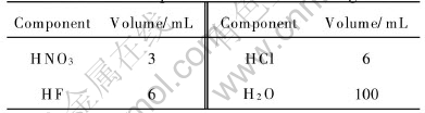
The cross-sections of the metallographic specimens were polished with alumina suspension, etched with Keller��s reagent, and observed by optical microscopy. The components of the Keller��s reagent are listed in Table 2.
Table 1 Chemical composition of A5083 aluminum and welding wire 5356 aluminium(mass fraction, %)
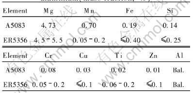
Table 2 Components of Keller��s reagent
The fatigue tests were carried out by a high- frequency fatigue test machine with a capacity of 100kN load. The fatigue specimens were machined perpendicular to the weld line. The weld was transverse to the stress axis in the S��N specimen(cross-weld). A sinusoidal load-time function was used, with the stress ratio set to 0.1. The oscillation frequency was in the interval of 110-120Hz in laboratory air. Shape and size of the fatigue test specimens of FSW and MIG are shown in Fig.1.
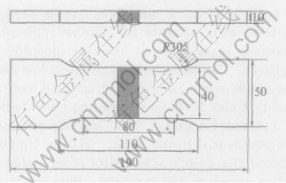
Fig.1 Shape and size of fatigue test specimens(mm)
Assessment of the fatigue behaviour of welded joints was obtained by applying statistical analysis to produce fatigue strength data as represented in the stress range to fatigue life(SN)-diagrams. The real area of interest to structures was the long life regime(Nf>106 cycles), but aluminium alloys didn��t generally show a fatigue limit asymptote so the fatigue characteristic values didn��t exist[11]. Data were therefore calculated by a statistical evaluation to get the fatigue characteristic values defined.
3 RESULTS AND DISCUSSION
3.1 Microstructures
Fig.2 shows a transverse macrograph of the MIG-pulse welded joint. The joint exhibits four distinct regions, namely: 1) base metal(BA); 2) fusion zone(FZ); 3) heat affected zone(HAZ); 4) weld. Optical micrographs of these regions indicated as (a)-(d) in Fig.2 are shown in Fig.3. The weld (a) of MIG-pulse welded joint shows typically cast dendritic structure. The microstructure of the fusion zone (b) near the weld is composed of equiaxed grains which are disparate in size, and some columnar grains along the direction of heat radiation. While fine-equiaxed grains exist in the fusion zone (c) near the base material with a relatively uniform size. With coarsening of grains in the HAZ to different degree, the most remarkable coarsening appears near the fusion zone. The base 5083 Al alloy is entirely composed of fully recrystallized structures.
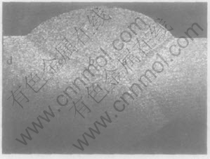
Fig.2 Transverse macrograph of MIG welded joint
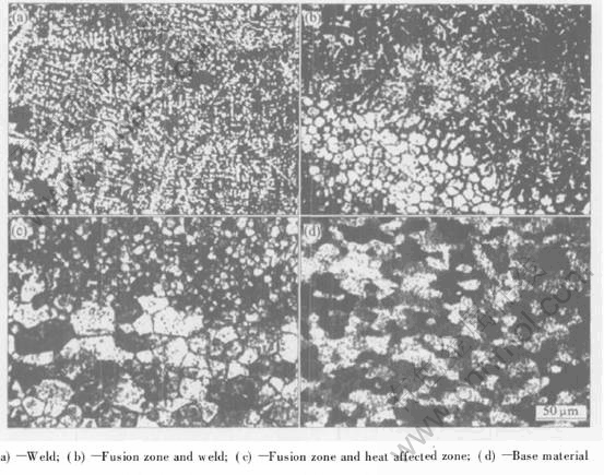
Fig.3 Microstructures of MIG-pulse welded joint
For the MIG-pulse welding with filler wire, the weld is based on components of Al 5356 and its crystallization process. As the molten pool is quite small and surrounded by metals, there is a considerable cooling rate and temperature gradient in the weld. These factors promote the columnar crystal greatly developing in the weld, even some of them extending to the centre of the weld.
FSW made an aesthetic joint without voids, cracking or distortion. Fig.4 shows the macrostructure of the joint and illustrates the details of the microstructural variation corresponding to regimes indicated by (a), (b), (c) and (d). The microstructure of the welded joint is formally divided into four zones: base materials, heat affected(HAZ), thermo-mechanically affected(TMAZ) and stirred zone.
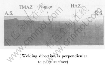
Fig.4 Transverse cross section of FSW A5083 joint(Nugget, HAZ, TMAZ)
As going from base material to the welding boundary and the centre of the weld, the crystal grain becomes small obviously (Fig.5). The structure of base material shows the structure a little elongated in the rolling direction. Since the stirring of FSW causes a rather high temperature and strain rate in the weld nugget, there are crystal nuclei recrystallizing there and their growth is limited by the strain. The weld nugget is composed of fine-equiaxed recrystallized grains, while the TMAZ is composed of coarse-bent elongated grains caused by squeezing action of the stirrer. Although both the advancing side(A.S.) and the retreating side(R.S.) have a boundary with the weld nugget, the boundary between base metal and stir zone of the advancing side is clearer than that of the retreating side.
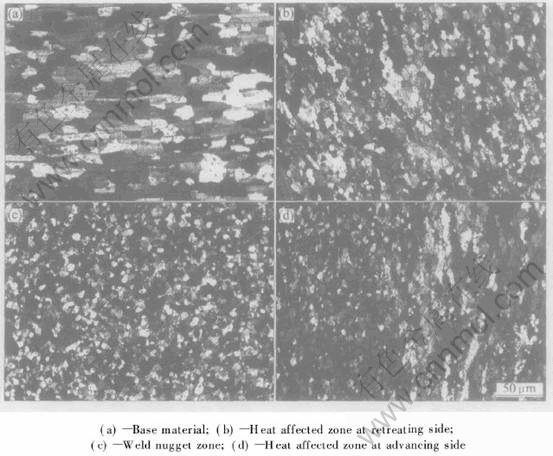
Fig.5 Microstructures of FSW joint for A5083 Al alloy
3.2 Fatigue properties
The fatigue test results show that most failures of MIG welded joints appear at the weld toe, because the stress concentration at this location is caused by the definite excess of weld metals for the good quality joints[12]. The fracture point of the FSW joint approaches to A.S. in the joint. Since the boundary of welding at the R.S. is clearer than that of A.S., the stress concentration generated at the advancing side is bigger than that at the retreating side.
Test results for each welding method are shown in Fig.6, along with two fatigue design curves recommended by IIW[13]. The spots with arrows may have higher values for the weld, because the failure does not occur here. Especially, since no waist is used for the fatigue specimens the likelihood for failure at the fixture increases. It can be seen from Fig.6 that all test results fall above FAT28 line, and only the test results of FSW fall above the two lines. In particular, the spots of FSW are far beyond the FAT28, which is the highest standard for transverse butt welds from one side for aluminium. Hence, these data indicate conservatism of the single-sided IIW fusion weld design curves when applied to friction stir welds.
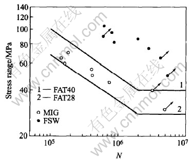
Fig.6 Comparison of fatigue test results with IIW design curves
Based on the loaded stress range and fatigue life(N), the S��N curves of each data group are fitted by the least square method. The fitting equations are listed below:
lgS=-BlgNf+A(1)
where S is the loaded stress range, Nf is the fatigue life, and B and A are fitting constants.
Generally, fitting constants of the S��N curve are expressed as follows[14]:
N=Cm/(����)m(2)
where Cm is the material constants, and m is the slope of the S��N curve. The relationships of the constants in Eqns.(1) and (2) are
m=1/B(3)
Cm=10A/B(4)
The curves fitted by Eqn.(1) is the curve at 50% probability of survival(mean line), shown in Fig.7.
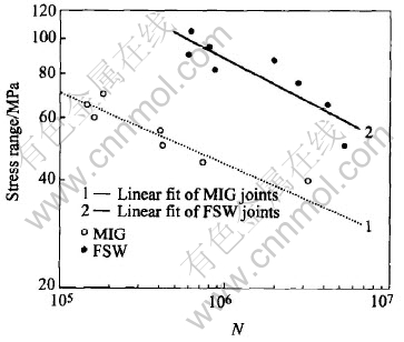
Fig.7 S��N curves of joints of MIG and FSW(R=0.1)
The S��N curves of MIG are expressed as
lgN=14.27-5.71lg����(5)
and the S��N curves of FSW are expressed as
lgN=14.17-4.21 lg����(6)
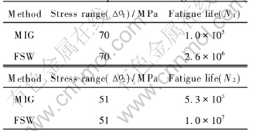
The fatigue strength ranges and lives are compared in Table 3. From the comparison, it can be drawn that the fatigue life of FS welds is 18-26 times longer than that of MIG-pulse welds under the stress ratio of 0.1.
Table 3 Comparison of fatigue life
Taking account of the randomness of the test results, it is needed to analyse the data with a statistic method[15]. The major means is using the S��N curve(in double-logarithmic plot) with an approximate double pulse-minus standard deviation. In most cases, the difference of test results should drop in the dispersion train of this standard deviation, which changes following the variation of cycle index. Fatigue data are processed using the method recommended by IIW, where these characteristic values are, in principle, values at a 95% survival probability(5% probability of failure) associated to a two sided confidence interval of 75% of the mean Xk and of the standard deviation stdv of ��=75%(12.5% probability of being above or below the extreme value of the confidence interval). The characteristic value can be figured out by the following procedure:
1) Backward computing the loaded stress range ���� and fatigue life N.
2) Figuring out the exponential m and constant lgCm in the formula below,
mlg����+lgN=lgCm(7)
3) Calculating the nominal value Xm and standard deviation stdv of lgCm, through m.
4) Supposing Xi is the logarithm value of test record, then the formulas for counting characteristic values are
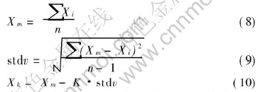
where n is the number of specimens, and K corresponding to n is listed in Ref.[13].
The number of specimens in both types is eight in this test, and K is calculated using the linear interpolation method: K=3.0.
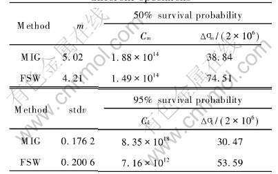
The constants m and Cm corresponding to 50% probability of survival are figured out through Eqns.(3) and (4), and the fatigue characteristic values are computed by Eqns.(7)-(10) to 95% probability of survival. All the parameters of S��N curve for different specimens are given in Table 4.
Table 4 Parameters of S��N curve for different specimens
In general, the fatigue properties of FS welds are wholely better than those of MIG-pulse welds. There are several reasons to explain this result. Firstly, the longitudinal and transverse residual stresses of FS welds are greatly reduced for the rigid fixing when welded. Then with the effects of upsetting and self sealing forced by the probe, the welds can not adsorb the hydrogen too much and the void of hydrogen does not appear in the welds too. Meanwhile, there is no excess of weld metal on the FS welds, which generates stress concentration on MIG-pulse welds and influences the fatigue performance, obviously. Without any filler metal, FSW is just a solid state welding of base materials, so it makes a sound structure and fine grains in the welds.
4 CONCLUSIONS
1) FS welds have a better appearance than MIG-pulse welds for the lack of voids, cracks and distortions. When compared to the parent plate, FSW joints exhibit similar fine grains, while MIG-pulse welds display a different cast microstructure due to the high heat inputs and the welding wire.
2) The fatigue data suggest conservatism of the appropriate fatigue design curves for single-sided welds recommended by IIW, when applied to friction stir welds. There are no universally accepted quality assurance procedures for friction stir welding, which need to be developed and incorporated into national and international standards.
3) The S��N curves of FSW and MIG-pulse joints show that the fatigue life of FS welds is 18-26 times longer than that of MIG-pulse welds under the stress ratio of 0.1 and the calculated fatigue characteristic value of each weld increases from 38.67MPa for MIG-pulse welds to 53.59MPa for FSW welds.
REFERENCES
[1]Thomas W M, Nicholas E D. Friction stir welding for the transportation industries [J]. Materials and Design, 1997, 18: 269-273.
[2]Davis C J, Thomas W M. Friction stir process welds aluminum alloys [J]. Welding Journal, 1996, 75: 415-422.
[3]Knipstrom K E, Pekkari B. Friction stir welding process goes commercial [J]. Welding Journal, 1997, 76: 55-63.
[4]Knipstrom K E. New welding method for aluminium [J]. Svetsaren, 1995, 3: 5-6.
[5]Peel M, Steuwer A, Preuss M, et al. Microstructure, mechanical properties and residual stresses as a function of welding speed in aluminium AA5083 friction stir welds [J]. Acta Materialia, 2003, 51: 4791-4801.
[6]Cabibbo M, Meccia E, Evangelista E. TEM analysis of a friction stir-welded butt joint of Al-Si-Mg alloys [J]. Materials Chemistry and Physics, 2003, 81: 289-292.
[7]Litynska L, Braun R, Staniek G, et al. TEM study of the microstructure evolution in a friction stir-welded AlCuMgAg alloy [J]. Materials Chemistry and Physics, 2003, 81: 293-295.
[8]Kluken A, Ranes M. Aluminium bridge constructions- welding technology and fatigue properties [J]. Svetsaren, 1995, 50: 13-15.
[9]Haagensen P J, Midling O T, Ranes M. Fatigue performance of friction stir butt welds in a 6000 series aluminium alloy [J]. Computional Mechanics Publications, 1995, 7-9: 225-237.
[10]Hagstrom J, Sandstrom R. Fatigue properties of welded T-joints in thin-walled aluminium profiles [J]. Materials Science Forum, 1996, 217-222: 727-32.
[11]Yao W X. Fatigue Life Prediction of Structures [M]. Beijing: National Defence Industry Press, 2003. 57-83.(in Chinese)
[12]Maddox S J. Review of fatigue assessment procedures for welded aluminium structures [J]. International Journal of Fatigue, 2003, 25(12): 1359-1378.
[13]Hobbacher A. Fatigue Design Welded of Joints and Components [M]. Cambridge: International Institute of Welding(IIW)/Abington Publishing House, 2002. 65-146.
[14]Guruey T R. Fatigue of Welded Structures [M]. London: Cambridge University Press, 1979. 214-224.
[15]HOU Li-xing. Fracture Behavior and Assessment of Welded Structure [M]. Beijing: China Machine Press, 2000. 221-352.(in Chinese)
Foundation item: Project supported by China FSW Center Beijing FSW Technology Limited Company, China
Received date: 2005-03-14; Accepted date: 2005-05-24
Correspondence: YANG Xin-qi, Professor, PhD; Tel: +86-22-27407022; E-mail: xqyang@tju.edu.cn
