
Trans. Nonferrous Met. Soc. China 26(2016) 348-358
Effects of reinforcement on wear resistance of aluminum matrix composites
A. PRAMANIK
Department of Mechanical Engineering, Curtin University, Bentley, Western Australia 6102, Australia
Received 31 March 2015; accepted 14 October 2015
Abstract:
The effect of reinforcement on the wear mechanism of metal matrix composites (MMCs) was investigated by considering different parameters, such as sliding distance (6 km), pressure (0.14-1.1 MPa) and sliding speed (230-1480 r/min). The wear mechanisms of an MMC and the corresponding matrix material under similar experimental conditions were compared on a pin-on-disc wear machine. The pins were made of 6061 aluminum matrix alloy and 6061 aluminum matrix composite reinforced with 10% Al2O3 (volume fraciton) particles (6-18 ��m). The disc was made of steel. The major findings are as follows: the MMC shows much higher wear resistance than the corresponding matrix material; unlike that of matrix material, the wear of MMC is very much linear and possible to predict easily; the wear mechanism is similar for both materials other than the three-body abrasion in the case of MMC; the reinforced particles resist the abrasion and restrict the deformation of MMCs which causes high resistance to wear. These results reveal the roles of the reinforcement particles on the wear resistance of MMCs and provide a useful guide for a better control of their wear.
Key words:
metal matrix composite; 6061 aluminium alloy; wear resistance; reinforcement;
1 Introduction
Aluminium alloys have been enormously used in aerospace and automobile industries due to superior properties, such as high specific strength, excellent low-temperature performance, exceptional corrosion resistance, chemical inertness [1]. However, the poor high-temperature performance and wear resistance are the main weaknesses of aluminium alloys. To overcome these problems, aluminium alloys reinforced by ceramic particles, known as metal matrix composites (MMCs) have been developed [2-7]. Though the incorporation of hard particles makes the processing of MMCs difficult [8,9], the wear resistance of this material increases significantly [10]. This leads to the application of particle-reinforced MMCs in automobiles and aircrafts [11], and possibly in biomedical fields [12,13]. The wear resistance of MMCs depends on the properties of reinforcements as well as the working condition and rubbing materials [14]. ZHANG et al [2,3] showed that a transition from sliding wear to severe wear occurred with increasing loads. The wear rates of particular materials increase with increasing the sliding speed and then decrease because of either surface oxidation or the effects of work hardening. JIANG et al [15] investigated the effects of load, sliding speed and longtime continuous friction on the friction and wear properties of Al-5%Si-Al2O3 composites. They found that with the increase of load, the wear loss and coefficient of friction increased. At higher sliding speed, the surface temperature of sample made the rate of producing of oxidation layer increase, while the wear loss and coefficient of friction decreased. With the increase of sliding distance, the coefficient of friction increased because the adhesive in the initial stage, then, the formation and destruction of oxide layer on the surface of sample tended to be a dynamic equilibrium, the surface state of sample was relatively stable and so did the coefficient of friction. The experiment showed that the main wear mechanism of Al-5%Si-Al2O3 composites includes abrasive wear, adhesive wear and oxidation wear. MIRANDA et al [16] assessed the contributions of metallic and ceramic reinforcements by producing aluminum�Csilicon hybrid composites reinforced with Ti and SiC particulates. The resistance and ductility properties (ultimate tensile strength and elongation to rupture) of AlSi-(Ti-SiC) hybrids, AlSi-SiC and AlSi-Ti composites were determined. The dry sliding behavior of AlSi, AlSi-Ti and AlSi-(Ti-SiC) composites against a gray cast iron counterface was analyzed. The controlling wear mechanisms were investigated. Unreinforced AlSi specimens were tested (mechanical and wear tests) under the same conditions for comparison purposes. They found that the wear behavior of AlSi-Ti/gray cast iron and AlSi-(Ti-SiC)/ gray cast iron tribo-pairs was improved when compared with that of AlSi/gray cast iron system. AlSi-11.25%Ti- 5%SiC hybrid composite exhibited the highest improvement in wear rate. MMCs generally demonstrate improved wear performance compared with the corresponding matrix material [17-19]. However, there are some reports where MMCs display wear resistance comparable with that of the corresponding matrix materials under certain conditions [18,20]. There are also inconsistent results on the effect of different tribological parameters on the wear of MMCs [17,20]. For example [21], the decrease of sliding wear resistance with the increase of volume fraction of particle in a 2014 Al-SiC/steel [22] and Cu-Al2O3 composite [23] has been noted.
From the above discussion, it is clear that there have been huge investigations on the wear behavior of MMCs, but an explicit understanding on the contribution of the reinforcement on the improved wear resistance of MMC is still missing. This research was conducted on a pin-on-disk wear testing unit to investigate the variables which affected the wear of ceramic particle reinforced aluminium matrix composite. This work gives a quantitative understanding on the improved wear resistance of MMCs due to the addition of reinforcements for a wide range of parameters by comparing the wear behavior of the alumina particle reinforced MMC and the corresponding matrix material. The effects of sliding distance (6 km), load and speed will be investigated systematically by comparing the wear properties of MMC and the corresponding 6061 aluminium matrix material. The role of ceramic reinforcements in improving the wear resistance of MMC will be better understood by comparing these two materials.
2 Experimental
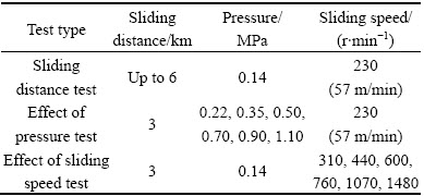
The materials were 6061 A1 matrix alloy and its composites reinforced by 10% (volume fraction) angular shaped Al2O3 particles (particle size is 6-18 ��m). Both of the materials were first direct chill (DC) cast and then hot-extruded. The samples with 50 mm in length and 8 mm in diameter were machined from a round bar with 30 cm in length and 15 cm in diameter. The selection of the rubbing pairs with MMCs is important as the different rubbing pairs may result in different wear behaviours. The steel components are widely used as wear counterfaces in tribo-systems [21]. In addition, steels are the most commonly used materials in daily life and it is likely that the MMC parts will be in contact/movement with steel parts during its practical application. Therefore, it is realistic to use steel disc as the wear counterface in this investigation. A rotating hardened steel disc of HRC 65 hardness was chosen as the wear counterface. A Plint-Cameron pin-on-disc wear machine was used for dry sliding tests. During the sliding test, the composite and matrix materials pin specimens were held against the rotating disc. The test was carried out up to the sliding distance of 6 km. The surfaces of both the pins and disc were cleaned with acetone before the wear test. A fixed track diameter of 80 mm was used in all tests. During the wear test, the steel disc was ground after first 2 km sliding distance. Therefore, the wear test was performed in two steps: in the first step, the test was done for 2 km without grinding the surface; in the second step, the disk surface was ground after 2 km of sliding test and the test continued. One parameter was varied while keeping the others constant during testing to see the effect of individual parameters. The ranges of the three parameters are given in Table 1.
Table 1 Details of wear testing conditions
3 Results and discussion
During the wear test, there were occasional high pitch sounds coming from the contact region. It is most likely to be caused by hard ceramic particles becoming exposed to the surface and being in direct contact with the steel disk. Unlike the softer matrix material phase, the ceramic does not deform plastically because of high strength ionic bonding between its constituent atoms. This suggests why the sounds remained audible for several minutes and then ceased suddenly, probably due to that the ceramic particles fractured or detached from the MMC. Much less noise was heard in the case of matrix material. In this case, soft rubbing sounds (similar to light furniture being pulled across a carpet) and little high pitch sounds were generated. Also, no grooves or scratches were seen on the steel disk after the test in the case of matrix material.
3.1 Effect of sliding distance
The experiment was conducted at a relatively low pressure (0.14 MPa) and sliding speed (230 r/min) over 6 km on each specimen. At the beginning of the wear test, a freshly machined MMC specimen was brought into contact with the steel disk. The specimen face had many groves and galleys which resulted from the previous machining and thus a fraction of total surface area was under wear initially. This effect disappeared with increasing the sliding distance and the specimen face became completely flat against the disk. Figure 1 presents the wears of MMC and the corresponding matrix material with increasing the sliding distance. It shows that the MMC has almost double wear resistant compared with the matrix material under the given sliding conditions. A linear relationship between the wear and sliding distance is found for the MMC. This graph is used to estimate the wear coefficient by Archard wear equation. The results show that the MMC behaves very much in accordance with the Archard wear equation in that the volume (or mass) of material removed is proportional to the sliding distance (Fig. 1). In addition to higher wear resistantce of MMC, the wear behaviour of an ex-situ reinforced material is more predictable than that of the unreinforced base material under the current experimental conditions. The material removed over several thousand meters could be predicted with very good confidence simply by observing Fig. 1. This will make the MMC a much more attractive material when designing components which move over each other because it would allow for appropriate estimates of the component service life.
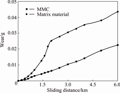
Fig. 1 Effect of sliding distance on wear of MMC and matrix material
The wear of matrix material was severe at the beginning of the test. A large amount of matrix material started to attach on the steel disk. The matrix material appeared more susceptible to adhesion and abrasive wear from small asperities on the steel disk. A linear relationship between the wear and distance and stable wear was displayed after the steel disk was ground at 2 km. The increased wear rate during the first 2 km sliding of matrix material happens due to the transfer of small flakes of matrix material onto the disk. The transferred layer would speed up the abrasive wear mainly for two reasons; self-matted materials sliding over each other tend to have a higher friction coefficient than when the materials are different and transferred material will tend to harden and act as a large asperity which will speed up abrasive wear. After 2 km, the disk was ground to remove transferred matrix material as wear test was not possible because of the adhesion of matrix material on the steel disk. This proved to be effective since the graph shows a more linear and stable wear of the matrix material after 2 km.
The photographs of wear debris (Fig. 2) and specimen surfaces (Fig. 3) show the irregular shape and size of debris as well as the smooth (with sliding marks) topography of both specimen surfaces after each test. These indicate that adhesion and abrasion are the primary wear mechanisms for both the MMC and matrix material [15]. The wear debris indicates that under these sliding conditions, adhesive and abrasive wear happens. The debris from the MMC is dull and granular and has dimensions of around 100 ��m, which suggests that these are metal oxides that were dislodged from the surface. The debris of matrix material is smaller and has a more lustrous finish than that of MMC (Fig. 2). This is probably because material was removed at a rate which did not allow an oxide film to form. As a result, softer and weaker matrix material was always exposed before any significant oxidation could occur.
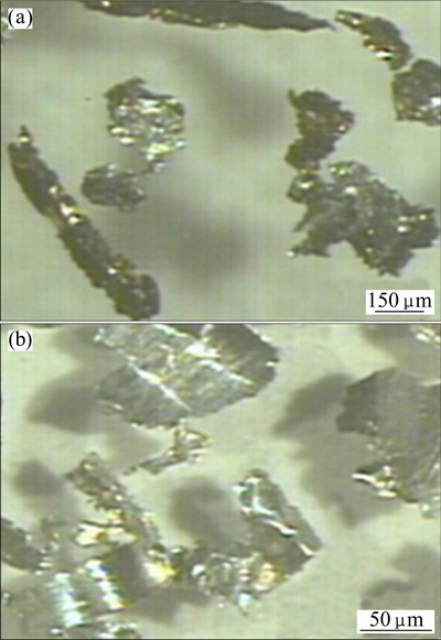
Fig. 2 Wear debris of MMC (a) and matrix material (b)
The worn MMC surface contains discontinuous grooves while the matrix material surface is full of continuous grooves (Fig. 3). The worn surface of MMC is relatively smooth and dark with discontinuous grooves. Shinny and lustrous surfaces are noted around the grooves. The dark regions are likely oxidation sites where a thin film of aluminium oxide must starts growing during the wear test. It is possible that the ferrous oxide could also start growing. The grooves present on the MMC specimen will be caused by abrasive wear either from the detached alumina particles that are free in the two sliding surfaces or from grooves in the steel disk that would plough through the softer matrix material. The effect of the ceramic reinforcement is noticed by comparing the worn MMC surface (Fig. 3(a)) with the matrix material surface (Fig. 3(b)) over the same distance. On the MMC specimen, the grooves appear scattered and dimpled almost as if there are some discontinuities in the line of ploughing. The grooves are evenly spaced and continuous from one end of the specimen face to the other in the matrix material. This suggests that the presence of reinforcement particles will limit the extent of abrasive wear that would otherwise happen in a monolithic metal. Abrasive wear requires one sliding surface to be predominantly harder than the other [5,24]. When the steel disk slides along the MMC surfaces, any asperities will plough through the matrix material but they will eventually encounter a ceramic particle. When this happens, ploughing can no longer continue and the asperities will break off [6]. This does not happen on the matrix material surface as no reinforcements are present.

Fig. 3 Worn surfaces of MMC (a) and matrix material (b) after 6 km sliding
3.2 Effect of pressure
The effects of pressure on the wear rate for MMC and matrix material are presented in Fig. 4. For MMC, the wear rate is negligible until the pressure is 0.7 MPa. The wear rate increases rapidly with the further increase of pressure. This results in larger wear debris and a rough MMC surface. A second transition from severe wear to sliding wear occurs with the further increase of pressure (0.9 MPa) though the rate of increase is lower than that at a pressure of 0.7 MPa. This is most likely due to rapid oxidation of the surface material and work hardening. The friction coefficients are lower compared with those of the wear versus distance experiments where lower pressure was used. A possible reason for this is that the higher pressure increases the surface temperature which causes more oxidation on the specimen surface. The evidence of surface oxidation is supported by the progressive increase of hardness and darker regions in the surface with the increase of pressure. The presence of a metal oxide film proved to be a valuable factor in improving the wear resistance of MMCs [8,25,26].
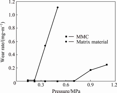
Fig. 4 Effects of pressure on wear rate for MMC and matrix material
Figure 4 also shows that the transition of sever wear for matrix material occurs at just above 0.2 MPa which is much lower than that of MMC. The matrix material generally transfers to the steel disk and the asperities on the disk increases gradually. The adhesion of the matrix material to the disk was so severe that the disk was ground after every test. The matrix material behaves differently because of the presence of less metallic oxide on the worn surfaces and the formation of larger wear debris. The wear debris once again shows the presence of oxidation which explains the reduction in friction. The MMC shows a wear roughly half of that of the matrix material in the wear versus sliding distance experiment at a lower pressure. But when both materials have the same wear mechanism at a higher pressure, the wear of MMC decreases to be less than 1/10 of that of the matrix material.
The enhanced wear resistance of MMC results from the hardness of reinforced particles and the ability of such particles to resist deformation [6]. In addition to improve the resistance to adhesive wear, the ceramic reinforcements delay the transition from mild to severe wear. The major differences between the wear mechanisms of MMC and matrix material are that the MMC develops an oxide film and has only small irregular shaped debris. The reason for the oxide film to grow on the MMC is that the certain areas of the specimen are in contact with the disk at any time. The ceramic reinforcements not only slow the wear rate but also provide a solid base on which the metal oxide grows (Fig. 5(a)). The matrix material wears away quickly until the oxide film is in contact with the disk as the matrix material is much softer than the metallic oxides. At this point, the hardened metal oxide does not provide enough support for the freshly exposed metal to start developing an oxide layer (Fig. 5(b)). This film growth is not possible in the matrix material as excessive material is added across the entire specimen surface. The removal of large fragments of matrix material is possible because the material is transferred to the steel disk by adhesion. This transferred material work hardens through continuous cyclic loading and it forms very large asperities on the disk surface. Without reinforcement particles in the matrix material, the hardened asperities could easily plough through it and produce large debris. Such debris is more difficult to form in the MMC because the reinforcement particles would prevent any asperities from penetrating through them. Thus, most of the surface area remains relatively intact and allows for metallic oxides to form wear debris of small size. It is evident that the oxidation occurs immediately adjacent to the areas where fresh MMC material is exposed. The specimen surfaces are oxidized completely at higher pressures because of the elevated temperature and the complete contact of the interface of disk and workpiece.
The wear resistance of MMCs is related to the bond between Al2O3 particles and 6061 A1 matrix alloy [27]. The microhardness of the reinforcement particles and the inter-particle distance are good indicators of the strength of interface between the particles and the matrix. Interfacial characteristics in particulate reinforced metal matrix composites can reasonably be evaluated by correlating the inter-particle distance with the microhardness of particles, wear and coefficient of friction [28]. Though the oxide films provide improved wear resistance, their effect can also be reduced if there is not enough support provided by the underlying material. This can happen due to localized weakening of the underlying material or from an asperity junction causing an extremely high normal stress concentration in that area which could result in premature severe wear. It is important to remember that manufacturing techniques can never guarantee reinforcement particles perfectly distributed throughout an MMC block. If a certain area has fewer particles per unit volume, that area will be less capable of supporting wear and shear stresses like the rest of the material. It is important to consider localized severe wear when designing brake systems. Even though certain pressure may appear harmless to an MMC during the wear testing, they can still cause significant material loss in some areas if specified break load exceeds. There is also the emphasis on making the MMC manufacturing techniques as consistent as possible and to ensure that the reinforcements are evenly distributed to avoid certain areas being weakened.

Fig. 5 Diagrams of likely process for oxide film growth on MMC (a) and matrix material (b)
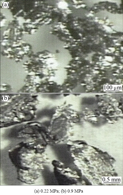
Fig. 6 Wear debris from MMC specimen at different pressures
The size of the wear debris depends on the pressure. At higher pressure, the wear debris is irregular in shape, bigger in size and has a more lustrous and shiny appearance than that at lower pressure for MMC (Fig. 6). This suggests that more MMC material fails beneath the contact interface at higher pressure which results in the formation of larger debris. This leaves a fresh surface underneath which would also get worn away. It is also supported by the appearance of worn surfaces. The worn surfaces appear to have progressively more oxidation as the pressure increases which are indicated by the dark regions (Fig. 7). This is due to the increased temperature which was generated by the high friction forces. Many grooves are noted among the darker oxidized regions. These were probably caused by the localized melting of matrix material that stretched across the face during sliding were noted in the sliding direction.
The debris from the matrix material appears to be formed by adhesive wear. The fragments are dark or grey in color and have an irregular shape. When the transition load is reached, the wear debris increases in size (dimensions exceeding 3 mm). Those have a very shinny surface finish, and are shaped like thin plates. Although an increase of wear debris size is observed for the MMC (Fig. 6), a fine granular texture similar to that of freshly exposed MMC specimen face during severe wear is noted. This is not found in the matrix material where debris has a much smoother texture (Fig. 8), and the plates appear to have lengthwise layering rather than grains running along their surface during severe wear. In contrast to the MMC specimen surfaces, the matrix material has a more lustrous appearance. The MMC specimen has dark regions (Fig. 7) that are randomly scattered across the surface, while the matrix material has grooves that are spaced much more consistently throughout the surface. In the matrix material, the same texture (lustrous and metallic) appears throughout the entire worn interface with no significant variation (Fig. 9). But the presence of bars (irregular lumps) is noted all over the surface (Fig. 9). A high ductility of matrix material may contribute these lumps.
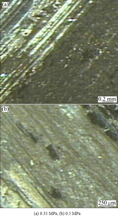
Fig. 7 Worn MMC surfaces at different pressures
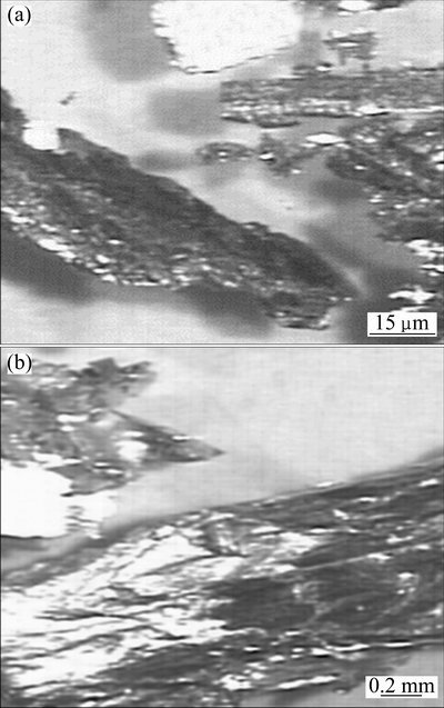
Fig. 8 Wear debris from matrix material at 0.22 MPa (a) and 0.35 MPa (b)
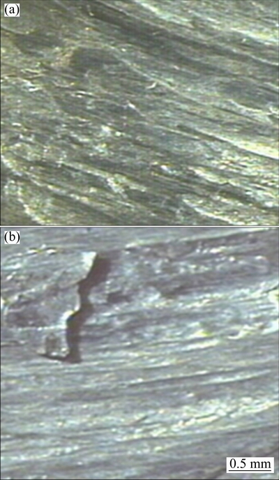
Fig. 9 Worn matrix material surface at 0.35 MPa (a) and 0.5 MPa (b)
3.3 Effect of sliding speed
Figure 10 shows the effect of sliding speed on the wear of MMC and the corresponding matrix material. The first four wear results (up to 600 r/min) for the MMC show that the wear rate increases steadily with increasing the sliding speed which is expected as more distance is covered per unit time at higher speeds. At 760 r/min, the wear rate drops slightly, and at 1480 r/min, the wear rate increases dramatically by 30 folds. This is due to severe wear and is evident by the large wear fragments and rough MMC surface at higher speeds. One of the possible causes for the reduced wear rate at the start could be the surface oxidation which may increase the local hardness and strength at the interface. But the drop of wear rate after 600 r/min is unexpected and so there must be another factor which causes the MMC to have increased wear resistance. It seems that the effect of oxidation increases after 600 r/min. During the wear process, two opposing processes, such as softening and hardening, take place simultaneously [30]. The softening of surface material occurs with the increase of temperature and strength, and the hardening occurs with the formation of metal oxides. The oxidation is a continuous process at all rotational speeds but it only becomes significant at speeds of 600 to 760 r/min. At this point, the metal oxide film thickness would possibly grow at a faster rate than the rate of material removal, meaning that only the strengthened and hardened metal oxide would be present at the interface and it would ��mask�� the softer matrix material underneath.
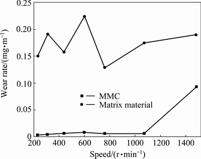
Fig. 10 Effect of sliding speed on wear rate of MMC and matrix material
The friction coefficients in the sliding distance and pressure test show no overall relationship between the controlled variables and the friction behavior. In this experiment, the results show a steep decline in measured friction coefficient with increasing the sliding speed in the early part of the test (230-600 r/min). After this speed, the friction coefficient appears to be around a minimum value of 0.2. This reduction in friction is the further evidence of the effects of oxidation on the wear process. The oxidation reduces the maximum shear stress of the surface and hence plastic flow and junction growth cannot occur as readily as in solid metal alloys.
Another likely reason for the reduced friction coefficient at larger rotational speeds can be the large amount of heat energy generation, which would soften the underlying metal. If this happens, the upper oxide film weakly bonds to the un-oxidized bulk material at higher temperatures. This can happen because even though the metal oxide interface is strong and has a higher melting temperature than the pure metal, the oxide film still needs to be supported in shear stress by the underlying materials. If the underlying portion of the specimen becomes weaker due to increased temperatures, it can no longer support the oxide film in shear stress. With the likelihood of a sliding interface, the asperities on the specimen surface no longer behave as idealized asperities. The theory of friction by adhesion predicts that the friction force will be the product of the true contact area and the shear strength of asperities. The shear strength of material does not drop at high temperature since the metal oxides have much higher melting temperatures and higher strength at higher temperatures. This means that the friction coefficient predicted by the adhesion theory would be lower at higher temperatures. While the upper portion of the interface would slide more readily due to weak underlying material, junction growth would still be retarded since the immediate interface material would be the metal oxide which will not deform plastically. This reduction in friction coefficient with increasing the rotational speed needs to be considered when designing break systems for machinery which operates at very high rotational speeds.
There are difficulties in conducting this test in the matrix material as the severe wear occurs very early (<200 m of sliding) which results in the transfer of matrix material to the steel disk. To ensure the conditions consistent, the steel disk was ground in order to remove this transferred layer for each test. There is no obvious relationship between the wear rate and sliding speed that was obtained for this particular experiment. This is because the matrix material is much softer than the steel and easily deformed during sliding. The transferred layers harden and result in more adhesive wear. This not only increases the wear rate but also causes continuous growth of the transfer layer. The same trend is noted for all the tests where the matrix material layer forms on the steel disk in the area of contact. Much less oxidations occur in the wear debris or on the specimen surface at higher speed. The friction coefficient of matrix material follows the trend similar to that of MMC, which shows a gradual decrease of friction coefficient with the increase of rotational speed. If less metal oxide is present on the surface and the increased rotational speeds result in lower friction coefficients, then, these suggest lower material shear strength due to higher temperatures. There is also the possibility of localized melting of the specimen at the asperity contacts where flash temperatures can reach as high as 1000 ��C which is well over the melting temperature (580 to 660 ��C) of 6061 Al alloy.
Figure 11 shows that the removed material of MMC is very irregular in shape and has a dark texture. The size of detached debris increases with the increase of sliding speed. This suggests that the adhesion between the asperities causes the material to deform and eventually separate from the surface with continuous sliding. The oxidation could occur on the surface and so the asperities would fail by brittle fracture. Another likely cause for the dark texture is that the metallic debris would be dislodged and then would oxidize outside the interface since it is still at a high temperature. At 1480 r/min, the debris has dimensions in excess of 3 mm and has a shiny yet granular texture similar to the debris found in other experiments. These fragments are clearly the result of severe wear. The worn surface at 440 r/min appears scattered regions where the oxidation would occur and only localized grooves where hard asperities would plough through the softer material. As the sliding speed increases, more specimen surface area is oxidized (as indicated by the dark regions), the grooves become more continuous and the plastic deformation starts to occur on the specimen. With the increase of sliding speed, the temperature, which facilitates the oxidation rate, increases. The evidence of this progression becomes stronger with more grooves that appear dark or grey as the sliding speed increases. Figure 12 shows the MMC surface after severe wear. There is a much rougher topography than the other specimens and the surface appears lustrous and a fresh layer of material is exposed (Fig. 12(b)).
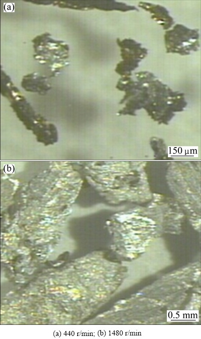
Fig. 11 Wear debris of MMC at different speeds

Fig. 12 Worn MMC surfaces at different speeds
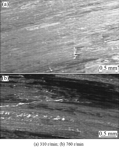
Fig. 13 Worn matrix material surface at different speeds
At lower sliding speed, the minor grooves on matrix material are discontinuous when running from one end of the specimen to another (Fig. 13(a)). At higher sliding speed, the grooves are continuous throughout the entire specimen surface and there is little or no grazing visible (Fig. 13(b)). This demonstrates that the increased temperature at higher speed softens the surface material and allows the complete abrasive wear to occur. Even though the ceramic reinforcements are harder than the steel and always present throughout the bulk specimen, they appear to have no effect of stopping the grooves at high sliding speeds. A possible reason for this is that the matrix material becomes softer and fails to hold the reinforcements during sliding. Thus, significantly less energy is needed to separate the ceramics from the matrix. The surface of matrix material deforms plastically and stretches across the specimen. This is evidenced by very thin plates and fibers which protrude over the circular edge in the direction of sliding. This phenomenon was not taken into account in the Archard wear equation. The model of adhesive wear predicted that both plastically and elastically deformed regions would be in true contact and only plastically deformed regions resulted in wear. The theory also predicted that the plastically deformed asperities will not change position, which simply stays in their location until they detach from the specimen. Clearly, this is not the case as the plastically deformed surface material flows when the temperatures are high enough. The worn surface shows a distinct layer which forms on the top of underlying matrix material. The layer has a darker colour and is not as lustrous as the matrix alloy.
Both materials show some noticeable trends as the sliding speed increases, those are gradual reduction in friction coefficient with increasing the sliding speed, darker surface appearance with increasing the sliding speed and more materials protruding from the specimen edge in the form of thin plates. Both materials have similar friction coefficient towards the latter stages of the experiment when high rotational speeds are used. Both the appearance of darker worn surfaces and increased hardness show the presence of oxidation. This of course results from the increased temperature.
3.4 Overall wear resistance of MMC
The results in the forgoing sections clearly show that the MMC has enhanced wear properties over the unreinforced matrix material. On several occasions, the calculated MMC wear is up to an entire order of magnitude smaller than that of matrix material. In addition to having better wear resistance on all tests throughout the study, the MMC also displays much more predictable wear behavior than the matrix material. The matrix material is susceptible to gross abrasive wear during the early stages of the experiment. The overall wear resistance of the MMC under all control conditions can be attributed to the ceramic particles which have the ability to restrict the deformation and to prevent hard asperities from causing abrasive wear [6,18]. The MMCs are shown to support the formation of metallic oxide films on their surfaces. This can be a valuable feature of the MMC if it is used in brake pads for vehicles. Since oxygen will always be available under these conditions, the brake pads will lose less mass of material because of continuous re-oxidation of worn surfaces.
4 Conclusions
1) The ceramic reinforcements improve the wear resistance of a monolithic metal in all changing variables of distance, load and sliding speed.
2) The ceramic reinforcements delay the transition load of a material from sliding wear to severe wear. Those also limit the effect of abrasive wear when sliding against a steel counterface.
3) The ceramic reinforcements enhance wear resistance by the following means: the resistance to deformation and thus stopping plastic deformation from happening in the immediate vicinity of the particle; preventing large wear fragments from becoming detached by gross seizure and abrasive wear; by providing a supported base on which a metallic oxide film can develop on the material surface, this film will harden and strengthen the interfacing material.
4) Both the materials have almost similar kinds of wear mechanism except the three-body abrasion and higher oxidation in the case of MMC.
5) The size of the debris of matrix material is bigger than that of MMC. For both the materials, the size of the debris increases with the increase of pressure and sliding speed.
References
[1] GAVA G H S, SOUZA R M D, de MELLO J D B, de  M C S, SCANDIAN C. Effect of load partition and particle distribution on micro-abrasive wear mapping of two-phase metal matrix composites [J]. Wear, 2013, 301(1): 130-136.
[2] ZHANG Z, ZHANG L, MAI Y W. Particle effects on friction and wear of aluminium matrix composites [J]. Journal of Materials Science, 1995, 30(23): 5999-6004.
[3] ZHANG Z, ZHANG L, MAI Y W. Wear of ceramic particle- reinforced metal-matrix composites [J]. Journal of Materials Science, 1995, 30(8): 1967-1971.
[4] DAVIM J P. Machining: Fundamentals and recent advance [M]. London: Springer, 2008: 127-166.
[5] PAN Y, FINE M, CHENG H. Sliding wear of an Al alloy SiC whisker composite [J]. Tribology Transactions, 1992, 35(3): 482-490.
[6] PRAMANIK A, ZHANG L, ARSECULARATNE J. Deformation mechanisms of MMCs under indentation [J]. Composites Science and Technology, 2008, 68(6): 1304-1312.
[7] PRAMANIK A. Electrical discharge machining of MMCs reinforced with very small particles [J]. Materials and Manufacturing Processes, 2015, 31(4): 397-404.
[8] DEUIS R, SUBRAMANIAN C, YELLUP J. Dry sliding wear of aluminium composites��A review [J]. Composites Science and Technology, 1997, 57(4): 415-435.
[9] PRAMANIK A, LITTLEFAIR G. Fabrication of nano-particle reinforced metal matrix composites [J]. Advanced Materials Research, 2013, 651: 338-343.
[10] BHATTACHARJEE D, MUTHUSAMY K, RAMANUJAM S. Effect of load and composition on friction and dry sliding wear behavior of tungsten carbide Particle-reinforced iron composites [J]. Tribology Transactions, 2014, 57(2): 292-299.
[11] PRAMANIK A, LITTLEFAIR G. Machining of titanium alloy (Ti-6Al-4V)��Theory to application [J]. Machining Science and Technology, 2015, 19(1): 1-49.
[12] PRAMANIK A, ZHANG L C, CHEN Y Q. Efficient machining of artificial hip joint components [J]. Advanced Materials Research, 2010, 97: 2269-2272.
[13] ZHANG L C, KIAT E, PRAMANIK A. A briefing on the manufacture of hip joint prostheses [J]. Advanced Materials Research, 2009, 76: 212-216.
[14] SARAVANAN S, SENTHILKUMAR M, SHANKAR S. Effect of particle size on tribological behavior of rice husk ash�Creinforced aluminum alloy (AlSi10Mg) matrix composites [J]. Tribology Transactions, 2013, 56(6): 1156-1167.
[15] JIANG X S, WANG N J, ZHU D G. Friction and wear properties of in-situ synthesized Al2O3 reinforced aluminum composites [J]. Transactions of Nonferrous Metals Society of China, 2014, 24(7): 2352-2358.
[16] MIRANDA G, BUCIUMEANU M, MADEIRA S, CARVALHO O, SOARES D, SILVA F S. Hybrid composites��Metallic and ceramic reinforcements influence on mechanical and wear behavior [J]. Composites Part B: Engineering, 2015, 74: 153-165.
[17] YIGEZU B S, JHA P, MAHAPATRA M. Effect of sliding distance, applied load, and weight percentage of reinforcement on the abrasive wear properties of in situ synthesized Al-12% Si/TiC composites [J]. Tribology Transactions, 2013, 56(4): 546-554.
[18] SANNINO A, RACK H. Dry sliding wear of discontinuously reinforced aluminum composites: Review and discussion [J]. Wear, 1995, 189(1): 1-19.
[19] RAJARAM G, KUMARAN S, RAO T S. Sliding wear behavior of Al-Si/Graphite composite [J]. Tribology Transactions, 2010, 54(1): 115-121.
[20] WANG A, RACK H. Transition wear behavior of SiC-particulate and SiC-whisker-reinforced 7091 Al metal matrix composites [J]. Materials Science and Engineering A, 1991, 147(2): 211-224.
[21] CARACOSTAS C A, CHIOU W A, FINE M E, CHENG H S. Wear mechanisms during lubricated sliding of XDTM 2024-AlTiB2 metal matrix composites against steel [J]. Scripta Metallurgica et Materialia, 1992, 27(2): 167-172.
[22] AlPAS A T, EMBURY J D. Wear mechanisms in particle reinforced and laminated metal matrix composites [C]//LUDEMA K C, BAYER R U, ed. Proceedings of the Conference on Wear of Materials. New York: ASME, 1991: 159-166.
[23] SAKA N, KARALEKAS D P. Friction and wear of particle- reinforced metal-ceramic composites [M]. New York: ASME, 1985, 784-793.
[24] NOMANI J, PRAMANIK A, HILDITCH T, LITTLEFAIR G. Chip formation mechanism and machinability of wrought duplex stainless steel alloys [J]. The International Journal of Advanced Manufacturing Technology, 2015, 80(5): 1127-1135.
[25] WILSON S, ALPAS A. Wear mechanism maps for metal matrix composites [J]. Wear, 1997, 212(1): 41-49.
[26] ZHANG J, ALPAS A. Transition between mild and severe wear in aluminium alloys [J]. Acta Materialia, 1997, 45(2): 513-528.
[27] THAM L, GUPTA M, CHENG L. Effect of limited matrix- reinforcement interfacial reaction on enhancing the mechanical properties of aluminium�Csilicon carbide composites [J]. Acta Materialia, 2001, 49(16): 3243-3253.
[28] THAKUR S K, DHINDAW B K. The influence of interfacial characteristics between SiCp and Mg/Al metal matrix on wear, coefficient of friction and microhardness [J]. Wear, 2001, 247(2): 191-201.
[29] YE Z, CHENG H, CHANG N S. Wear characteristics of particle-reinforced aluminum matrix composites in lubricated reciprocating contacts [J]. Tribology Transactions, 1998, 41(3): 359-367.
[30] ISLAM M N, ANGGONO J M, PRAMANIK A, BOSWELL B. Effect of cooling methods on dimensional accuracy and surface finish of a turned titanium part [J]. The International Journal of Advanced Manufacturing Technology, 2013, 69(9-12): 2711-2722.
��ǿ����������ϲ�����ĥ�Ե�Ӱ��
A. PRAMANIK
Department of Mechanical Engineering, Curtin University, Bentley, Western Australia 6102, Australia
ժ Ҫ��ͨ�����Dz�ͬ�IJ�����������������(6 km)��ѹ��(0.14~1.1 MPa)�ͻ����ٶ�(230~1480 r/min)���о���ǿ��Խ��������ϲ���(MMC)ĥ�������Ӱ�졣��һ̨��-��ʽĥ��������ϣ��Ա��о���ͬʵ��������MMC����Ӧ������ϵ�ĥ�����������6061�����Ͻ����10% Al2O3 (�������)����(6~18 ��m)��ǿ��6061�������ϲ�����ɣ����ɸ�����ɡ��õ�������Ҫ���ۣ�MMC����Ӧ�Ļ�����Ͼ��и��ŵ���ĥ�ԣ��������ϲ�ͬ��MMC��ĥ���������ԵĺͿ�Ԥ��ģ�����MMC������ĥ��ĥ���⣬���ֲ��ϵ�ĥ��������ƣ���ǿ���ܿ�ĥ������MMC�ı��Σ��Ӷ�����MMC���и��ŵ���ĥ�ԡ����ý����ʾ����ǿ����������MMC��ĥ�Է�������ã���Ϊ���õؿ�����ĥ���ṩ����Чָ����
�ؼ��ʣ����������ϲ��ϣ�6061���Ͻ���ĥ�ԣ���ǿ��
(Edited by Mu-lan QIN)
Corresponding author: A. PRAMANIK; Tel: +61-8 9266 7981; Fax: +61-8 9266 2681; E-mail: alokesh.pramanik@curtin.edu.au
DOI: 10.1016/S1003-6326(16)64125-0
Abstract: The effect of reinforcement on the wear mechanism of metal matrix composites (MMCs) was investigated by considering different parameters, such as sliding distance (6 km), pressure (0.14-1.1 MPa) and sliding speed (230-1480 r/min). The wear mechanisms of an MMC and the corresponding matrix material under similar experimental conditions were compared on a pin-on-disc wear machine. The pins were made of 6061 aluminum matrix alloy and 6061 aluminum matrix composite reinforced with 10% Al2O3 (volume fraciton) particles (6-18 ��m). The disc was made of steel. The major findings are as follows: the MMC shows much higher wear resistance than the corresponding matrix material; unlike that of matrix material, the wear of MMC is very much linear and possible to predict easily; the wear mechanism is similar for both materials other than the three-body abrasion in the case of MMC; the reinforced particles resist the abrasion and restrict the deformation of MMCs which causes high resistance to wear. These results reveal the roles of the reinforcement particles on the wear resistance of MMCs and provide a useful guide for a better control of their wear.
