
J. Cent. South Univ. (2012) 19: 2650-2655
DOI: 10.1007/s11771-012-1323-8![]()
Closed-form solution to thin-walled box girders considering effects of shear deformation and shear lag
ZHOU Wang-bao(������)1, JIANG Li-zhong(������)1,2, LIU Zhi-jie(��־��)1, LIU Xiao-jie(��С��) 1,2
1. School of Civil Engineering, Central South University, Changsha 410075, China;
2. National Engineering Laboratory for High Speed Railway Construction (Central South University), Changsha 410075, China
? Central South University Press and Springer-Verlag Berlin Heidelberg 2012
Abstract:
Considering three longitudinal displacement functions and uniform axial displacement functions for shear lag effect and uniform axial deformation of thin-walled box girder with varying depths, a simple and efficient method with high precision to analyze the shear lag effect of thin-walled box girders was proposed. The governing differential equations and boundary conditions of the box girder under lateral loading were derived based on the energy-variational method, and closed-form solutions to stress and deflection corresponding to lateral loading were obtained. Analysis and calculations were carried out with respect to a trapezoidal box girder under concentrated loading or uniform loading and a rectangular box girder under concentrated loading. The analytical results were compared with numerical solutions derived according to the high order finite strip element method and the experimental results. The investigation shows that the closed-form solution is in good agreement with the numerical solutions derived according to the high order finite strip method and the experimental results, and has good stability. Because of the shear lag effect, the stress in cross-section centroid is no longer zero, thus it is not reasonable enough to assume that the strain in cross-section centroid is zero without considering uniform axial deformation.
Key words:
1 Introduction
Box girders have good structural properties of light weight and large flexural and tortional rigidity, and desirable lateral-distributed load could be obtained by installing a small amount of diaphragms. The prestressed reinforcements in the top and bottom plates could effectively resist the positive and negative moments, which are suitable for continuous beam bridges, rigid frame bridges and especially continuous horizontally curved box girder bridges. Cantilever erection, cantilever casting and incremental launching method are all available in dealing with construction of box girder, which satisfies the demand of modern construction. Therefore, box girders have been widely used and promoted in bridge construction [1-3]. However, as for the wide box girder with web plates of large spacing under a symmetrical loading, the distribution of bending stresses in thin-walled box girders at any transverse section is non-uniform, and in general, the stresses at the web-flange conjunction reach their maximum, decreasing towards the middle point of the top and bottom slabs and cantilever flanges. Its deformation does not obey the elementary beam theory. This phenomenon is called the shear lag effect [4-5]. The stress concentration induced by shear lag effect is likely to cause failure of the box girder when it is severe [1, 6-8].
The shear lag of the box girder has been studied without considering the effect of shear deformation [9-13]; NI [14] proposed warping displacement mode to consider the self-balancing of axial force, yet without taking the shear deformation of cross-section into account; the researches (e.g., Refs. [11-14]) were all based on the assumption that the functions of longitudinal warping amplitude of the upper and lower flange and the cantilever plate were the same. While LUO [15-18] proved that the assumption was valid only for rectangular box girders but invalid for trapezoidal box girders, so this assumption made in Refs. [11-14] was abandoned. Three longitudinal displacement functions and uniform axial displacement functions for thin-walled box girder with varying depths for uniform axial deformation were taken into account, which were proved to be more reasonable. However, LUO [15-18] didn��t consider the uniform axial deformation of the whole cross-section due to shear lag effect. The uniform axial deformation made the centroidal axis no longer the neutral axis, which meant that axial stress existed in the centroid of the cross section.
In this work, a simple and efficient analytical model with high precision was proposed, taking shear lag, shear deformation and uniform axial deformation into account. The governing differential equations and boundary conditions of the box girder were derived based on energy-variational method [2, 19-20], and the closed-form solution was found. Finally, results were compared with numerical solutions derived according to the high order finite strip method and the experimental results [17]. The calculation method was based on box girder under bending load.
2 Basic assumptions
1) Let ![]() represent longitudinal warping displacement function of the cantilever plate, the center of top plate and bottom plate, respectively (Fig. 1). According to the fact that the lateral shear strains of the edge of cantilever plate, the center of the roof plate and base plate are all zero, and considering the compatibility of the displacement of the flange and the web and the compatibility coordination of the displacement of the cantilever plate and the top plate, we can obtain
represent longitudinal warping displacement function of the cantilever plate, the center of top plate and bottom plate, respectively (Fig. 1). According to the fact that the lateral shear strains of the edge of cantilever plate, the center of the roof plate and base plate are all zero, and considering the compatibility of the displacement of the flange and the web and the compatibility coordination of the displacement of the cantilever plate and the top plate, we can obtain
![]()
![]()
Therefore, it could be assumed that the longitudinal warping displacement of the top plate, cantilever plate and bottom plate are expressed as
![]() (1a)
(1a)
![]() (1b)
(1b)
![]() (1c)
(1c)
where ![]() ; 2b1, b2, 2b3 are the depths of top plate, cantilever plate, and bottom plate, respectively; hi (i=1, 2, 3) are coordinate values of the middle section of top plate, cantilever plate and bottom plate, respectively; H is the total height of the girder.
; 2b1, b2, 2b3 are the depths of top plate, cantilever plate, and bottom plate, respectively; hi (i=1, 2, 3) are coordinate values of the middle section of top plate, cantilever plate and bottom plate, respectively; H is the total height of the girder.
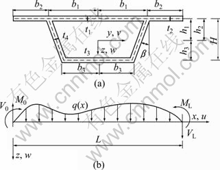
Fig. 1 Box girder of trapezoidal cross section: (a) Cross section; (b) Coordinate and load
2) The longitudinal displacement of each point on the cross-section of a box girder can be assumed to be the sum of the plane surface deflection, warping displacement, and uniform axial displacement. Using u0(x), the self-balanced axial force can be obtained:
![]()
![]() (2a)
(2a)
![]()
![]() (2b)
(2b)
![]() (2c)
(2c)
where ![]() ;
; ![]() ; ��(=��sQ/GAw) is the average shear strain; ��s is the shear coefficient; Aw is the cross-sectional area of the two web plates; G is the shear modulus; Q(x) is the shear force; W(x) is the vertical deflection of the box girder; U(x) (i=1, 2, 3) are the functions of longitudinal warping amplitude; U0 is the uniform longitudinal displacement; 2b1, b2, 2b3 and t1, t2, t3 are the depths and thicknesses of top plate, cantilever plate, and bottom plate, respectively; �� and t4 are the slope angle and thickness of the web.
; ��(=��sQ/GAw) is the average shear strain; ��s is the shear coefficient; Aw is the cross-sectional area of the two web plates; G is the shear modulus; Q(x) is the shear force; W(x) is the vertical deflection of the box girder; U(x) (i=1, 2, 3) are the functions of longitudinal warping amplitude; U0 is the uniform longitudinal displacement; 2b1, b2, 2b3 and t1, t2, t3 are the depths and thicknesses of top plate, cantilever plate, and bottom plate, respectively; �� and t4 are the slope angle and thickness of the web.
3) Vertical compression of the flange, lateral strain and bending, and shear deformation out of the plate are small enough to be neglected.
3 Governing differential equation and its solution
3.1 Expression of total potential energy
Based on the aforementioned expression of the vertical displacement on the cross-section, the strain of flange at any point is given by
![]() (3a)
(3a)
![]() (3b)
(3b)
![]() (3c)
(3c)
![]() (3d)
(3d)
where y is replaced by ![]() when i=2;
when i=2; ![]() are the longitudinal positive strains of the top plate, cantilever plate, bottom plate and web plate, respectively;
are the longitudinal positive strains of the top plate, cantilever plate, bottom plate and web plate, respectively; ![]() are the shear strains of the top plate, cantilever plate, bottom plate and web plate, respectively.
are the shear strains of the top plate, cantilever plate, bottom plate and web plate, respectively.
According to law of conservation of energy, the external potential energy caused by bending can be expressed in terms of internal force as
![]() (4)
(4)
The strain energies of top plate, cantilever plate, bottom plate and web plate can be derived based on energy-variational method in conjunction with above assumption as follows:
![]() (5)
(5)
![]() (6)
(6)
![]() (7)
(7)
![]() (8)
(8)
Substituting Eq. (3) into Eqs. (5)-(8) results in

![]() (9)
(9)
![]()
![]() (10)
(10)
![]()
![]() (11)
(11)

 (12)
(12)
where E is the elastic modulus; G is the shear modulus;![]() ;
;![]() (3cos��).
(3cos��).
If the origin of coordinate system is set at the mid-height location of the cross-section, we get
![]() (13)
(13)
Consequently, the potential energy of the total system is
![]() (14)
(14)
3.2 Governing differential equations
Substituting Eqs. (4), (9)-(12) into the above equation, and letting �Ħ�=0, we get the governing differential equations through integration of each term:
![]() (15)
(15)
![]() (16)
(16)
![]() (17)
(17)
![]() (18)
(18)
![]() (19)
(19)
![]() (20)
(20)
![]() (21)
(21)
where![]() ;
;![]() ;
; ![]() ;
; ![]() .
.
Equations (15)-(17) are the governing differential equations of the deformation of the box girder, and Eqs. (18)-(21) are the boundary conditions of the deformation of the box girder.
3.3 Closed-form solution of governing differential equations
The first integration of Eq. (16) gives
![]() (22)
(22)
Substituting Eq. (22) into Eq. (16), we obtain
![]() (23)
(23)
![]() (24)
(24)
where ![]() ,
, ![]() , ��0=��/ (��-?2), and
, ��0=��/ (��-?2), and ![]() .
.
Substituting Eqs. (23)-(24) into Eq. (17) gives
 (25)
(25)


where ![]() .
.
The homogeneous solution of Eq. (26) is
![]() (26)
(26)
When q is constant, the particular solution of Eq. (25) is
![]() (27)
(27)
The general solution of Eq. (26) is
![]()
![]() (28)
(28)
![]()
![]() (29)
(29)
where cij is the element of eigenvector of A-1B, and c3j=-1; ��i (i=1, 2, 3) are three eigen values of A-1B; di and ei (i=1, 2, 3) are the constants of integration.
Substituting Eq. (28) into Eq. (23)-(24) yields
![]()
![]() (30)
(30)
![]()
![]() (31)
(31)
![]()
![]() (32)
(32)
![]()
![]() (33)
(33)
The first derivative of w is ![]() therefore,
therefore,
![]()
![]() (34)
(34)
where![]() , and
, and![]() are the constants which are related to the section dimension; ci (i=1, ��, 6) are the constants of integration.
are the constants which are related to the section dimension; ci (i=1, ��, 6) are the constants of integration.
According to the boundary conditions Eqs. (18)- (21), we can obtain the unknown coefficients. Then, by substituting Eqs. (29), (31) and (33) into the following stress calculating formula, we can obtain the close-form solution of longitudinal stress at each point of the web and flange:
![]() (35)
(35)
![]() (36)
(36)
where y is replaced by ![]() when i=2.
when i=2.
From Eqs. (28)-(34), we can learn that only Eq. (34) has the term of shear deformation, which means that shear deformation has influence on deflection, while it has no influence on normal stress and shear lag effect. From Eq. (35), we can learn that the centroid of cross-section is no longer zero at the location of the neutral axis, which means that longitudinal stress exists at the centroid of cross-section due to shear lag effect.
4 Verification of closed-form solution
4.1 Comparison of closed-form solution, finite strip method and experimental results of a rectangular box girder
To verify the proposed formula, a rectangular beam model made by organic glass is investigated [17]. The section size and the measurement point arrangement of this beam model with a span of 0.8 m and diaphragms installed at beam ends are shown in Fig. 2. Two concentrated loads equal in magnitude to 0.272 2 kN are symmetrically applied on the top of the web plate at the mid-span section. The elastic modulus of PMMA is measured to be 3 000 MPa, the Poisson ratio is taken as 0.385, and the strain of mid-plane of the plate is taken as the average value of the results of upper and lower measurement points.
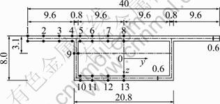
Fig. 2 Rectangular box girder section (Unit: 10-2 m)
The comparison of results from closed-form solution (P1), the experimental results (P) and the numerical solutions (P2) derived according to the high order finite strip method are shown in Fig. 3. It could be calculated from Fig. 3 the average values of P1/P and P2/P are 1.000 2 and 1.012 2, respectively, and the variances of the ratios are 0.002 4 and 0.001 6. The stress at the centroid point of the cross-section of box girder is no longer zero. It can be concluded that results from the close-form solution correlated are in good agreement with the experimental results, and have good stability.
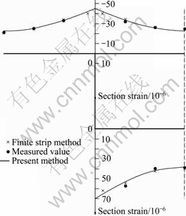
Fig. 3 Section strain at mid-span of simply-supported rectangular section box girder under concentrated load
4.2 Comparison of closed-form solutions and numerical solutions derived according to high order finite strip method in a trapezoidal box girder
A simply supported trapezoidal box girder with a span of 50 m and the section size shown in Fig. 4 is investigated. The elastic modulus of concrete E=3.1��104 MPa, and the Poisson ratio ��=0.17. 1) Two concentrated loads equal in magnitude to 20 kN are symmetrically applied on the top of the web plate at the mid-span section. 2) A uniform load of q=2 kN/m is applied on the top of the web along the span.
Table 1 and Fig. 5 show the analytical results obtained from different methods. It could be concluded from Table 1 and Fig. 5 that the average values of the ratios of the closed-form solutions to the numerical solutions for two different kinds of loadings are 1.02 2 and 1.011, respectively, and the variances of the ratios are 0.000 7 and 0.000 3, respectively. For trapezoidal box girder, we can draw the same conclusion as that for rectangular box girder. At the same time, the stress at the centroid point of the cross-section of box girder is no longer zero. It is not reasonable enough to neglect the uniform axial deformation. The proposed method in this work is more reasonable.
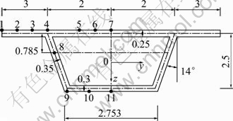
Fig. 4 Trapezoidal box girder section (Unit: 10-2 m)
Table 1 Comparison of section strain at mid-span of simply-supported trapezoidal section box girder under uniform load (10-6)
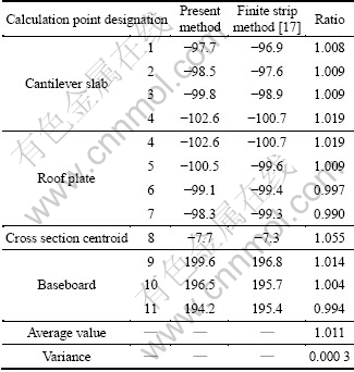
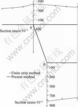
Fig. 5 Section strain at mid-span of simply-supported trapezoidal section box girder under concentrated load
5 Conclusions
1) A method is proposed for direct calculation of stress in box girder. Verification of the method is performed by comparing the results with other analytical results using finite strip method and experimental results.
2) The shear effect influences only the deflection, while has no impact on longitudinal positive strain and shear lag. Therefore, both shear lag and shear effect should be considered when calculating the deflection while only shear lag should be considered when calculating the section stress.
3) The stress at cross-section centroid is no longer zero due to shear lag effect. Therefore, it is not scientific enough to assume the strain in cross-section centroid to be zero without considering the uniform axial deformation. The proposed method is more reasonable.
4) Theoretical analysis method for the shear lag effect in box girder is explored, which provides important basis for the shear lag calculation in thin-walled box girder bridges.
References
[1] REISSNER E. Analysis of shear lag in box beams by the principle of minimum potential energy [J]. Quarterly of Applied Mathematics, 1946, 5(3): 268-278.
[2] VISNJIC G, NOZAK D, KOSEL F, KOSEL T. Shear-lag influence on maximum specific bending stiffness and strength of composite I-beam wing spar [J]. Journal of Aerospace Engineering, 2011, 225(5): 501-511.
[3] LERTSIMA C, CHAISOMPHOB T. Deflection of simply supported box girder including effect of shear lag [J]. Computers and Structures, 2005, 84: 11-18.
[4] KUZMANOVIC B O, GRANAM H J. Shear lag in box girder [J]. Journal of the Structural Division, ASCE, 1981, 107(9): 1701-1712.
[5] ZHOU Jian, TU Ling-kang. Re-study on the shear lag in the wide-flange beams [J]. Engineering Mechanics, 1994, 11(2): 65-75. (in Chinese)
[6] FABRIZIO G, GIANLUCA R, GRAZIANO L. Partial interaction analysis with shear-lag effects of composite bridges: A finite element implementation for design applications [J]. Advanced Steel Construction, 2011, 7(1): 1-16.
[7] QI Jing-jing, JIANG Li-zhong. Effects of interface slip and semi-rigid joint on elastic seismic response of steel-concrete composite frames [J]. Journal of Central South University of Technology, 2010, 17(6): 1327-1335.
[8] NIE Jian-guo, LI Fa-xiong. Practical design method for steel-concrete composite beam considering shear lag effect [J]. Engineering Mechanics, 2011, 28(11): 45-51. (in Chinese)
[9] CHANG S T. Shear-lag effect in simply supported prestressed concrete box-girder bridge [J]. Journal of Bridge Engineering, 2004, 9(2): 178-184.
[10] LIN Peng-Zhen, ZHOU Shi-Jun. Analysis on shear-lag effect of box girders based on flange-slab shear deformation law [J]. Journal of the China Railway Society, 2011, 43(4): 100-104.
[11] LI Chang-feng, DU Wen-xue. Effect of curvature radius and transverse distribution of load on shear lag for curved box girders [J]. Advanced Materials Research, 2011, 163/164/165/167: 1555-1560.
[12] ZHANG Hui, DESROCHES R, YANG Zi-jiang; LIU Shi-zhong. Experimental and analytical studies on a streamlined steel box girder [J]. Journal of Constructional Steel Research, 2011, 66(7): 906-914.
[13] GAN Ya-nan, ZHOU Guang-chun. Dynamics response of thin-walled rectangle box girders considering shear lag effect [J]. Journal of Vibration, Measurement and Diagnosis, 2011, 32(2): 198-201.
[14] NI Yuan-zeng. Shear lag problems in wide channel beams [J]. China Civil Engineering Journal, 1986, 19(4): 32-41. (in Chinese)
[15] LUO Qi-zhi. Shear lag of thin-walled curved box girder bridges [J]. ASCE J Engrg Mech, 2000, 126(10): 1111-1114.
[16] LUO Qi-zhi. Shear lag in box girder bridges [J]. Journal of Bridge Engineering, 2002, 7(5): 308-313.
[17] LUO Qi-zhi. Theory and model test studies of the shear lag in thin walled box girders based on energy principle [D]. Hunan University, 2005. (in Chinese)
[18] LUO Qi-zhi. Geometric nonlinear analysis of curved box continuous girders considering shear lag effect [J]. Advanced Materials Research, 2011, 243-249: 1811-1816.
[19] HU Hai-chang. Variational principles in elasticity [M]. Beijing: Science Press, 1981: 43-65. (in Chinese)
[20] SUN Fei-fei, ORESTE S. BURSI, A M ASCE. Displacement-based and two-field mixed variational formulations for composite beams with shear lag [J]. Journal of Engineering Mechanics, 2005, 131(2): 199-210.
(Edited by YANG Bing)
Foundation item: Projects(51078355, 50938008) supported by the National Natural Science Foundation of China; Project(CX2011B093) supported by the Doctoral Candidate Research Innovation Program of Hunan Province, China; Project(20117Q008) supported by the Basic Scientific Research Funds for Central Universities of China
Received date: 2011-09-02; Accepted date: 2012-04-26
Corresponding author: JIANG Li-zhong, Professor, PhD; Tel: +86-15116335688; E-mail: zhouwangbao@163.com
Abstract: Considering three longitudinal displacement functions and uniform axial displacement functions for shear lag effect and uniform axial deformation of thin-walled box girder with varying depths, a simple and efficient method with high precision to analyze the shear lag effect of thin-walled box girders was proposed. The governing differential equations and boundary conditions of the box girder under lateral loading were derived based on the energy-variational method, and closed-form solutions to stress and deflection corresponding to lateral loading were obtained. Analysis and calculations were carried out with respect to a trapezoidal box girder under concentrated loading or uniform loading and a rectangular box girder under concentrated loading. The analytical results were compared with numerical solutions derived according to the high order finite strip element method and the experimental results. The investigation shows that the closed-form solution is in good agreement with the numerical solutions derived according to the high order finite strip method and the experimental results, and has good stability. Because of the shear lag effect, the stress in cross-section centroid is no longer zero, thus it is not reasonable enough to assume that the strain in cross-section centroid is zero without considering uniform axial deformation.
