
J. Cent. South Univ. Technol. (2011) 18: 230-237
DOI: 10.1007/s11771-011-0684-8
![]()
Corrosion risk assessment of chloride-contaminated concrete structures using embeddable multi-cell sensor system
LU Shuang(¬ˬ), BA Heng-jing(�ͺ㾲)
School of Civil Engineering, Harbin Institute of Technology, Harbin 150006, China
? Central South University Press and Springer-Verlag Berlin Heidelberg 2011
Abstract:
Monitoring the service condition of concrete structures requires the quantitative assessment of properties and corrosion rate of structural steels surrounded by concrete. A multi-cell sensor system that included a reference electrode, a chloride content sensor, a macrocell current unit and an electrical resistance measurement unit was developed. This system provided the following important electrochemical data in the cover-zone concrete on site: open circuit potential, macrocell current from anodes to cathode, chloride profile, concrete resistance and corrosion rate of built-in anodes. The experimental results show that the macrocell current increases when the chloride content in concrete is higher. Thus, monitoring the chloride content is a good method for monitoring the corrosion state. The chloride ion content and cover depth are the key factors that affect the electrical resistance of concrete. Without considering the temperature and time, a simplified model of the instantaneous corrosion rate of steel rebar in a concrete structure based on the measured chloride contents and concrete resistance was proposed. The test results further prove the reliability of this simplified predicting model.
Key words:
1 Introduction
Generally, the corrosion of steels in marine concrete structures occurs because of either a reduction in alkalinity of the steel due to the carbonation of concrete or leaching of alkalis or the presence of a significant quantity of chloride ions in the concrete [1]. Corrosion monitoring technology has been extensively explored, and it is still being investigated, including measurement methods for corrosion sensor applications [2]. The central issue in all these studies is to provide indicative information related to both the integrated quality of the concrete and the corrosion state of the reinforcement [3].
Because chloride ions are the major contributing factors that affect the corrosion state of the steel rebar embedded in concrete, several electrochemical sensors have been developed recently to monitor the corrosion in the chloride-contaminated concrete structures [4-5]. For example, MONTEMOR et al [6] presented a non- destructive chloride-sensitive sensor element. They found that an Ag/AgCl sensor demonstrated good stability and sensitivity in mortar and concrete structures. VERA et al [7] evaluated the effect of OH- interference on the detection precision of the Cl- ISE (ion selective electrode) and suggested that this effect could influence the accurate measurement of low free Cl- concentrations. For chloride-contaminated concrete structures, it is also important to monitor the macro-cell current [8]. Since 1990, a special macrocell system has been used worldwide to monitor the corrosion risk of new concrete structures as a time-to-corrosion warning system [9]. ELSENER [10] discussed the influence of cover depth and conductivity on the macrocell current and studied the potential distribution using model-macrocells in water and mortar. The results indicated that the resistance distribution in the mortar affects macro-cell currents and the oxygen supply when the concrete structure is in high-resistance. Currently, the macrocell current sensor (MCS) and the chloride ion content sensor (CCS) have been recommended as effective methods to evaluate the corrosion state of the chloride-contaminated concrete structures [11-12].
Though the concrete resistance does not determine whether steel is being actively corroded in concrete, it can indirectly elevate the corrosion risk of steel embedded in cover-zone concrete. Thus, several in-suit sensors and novel methods have been developed to monitor the cover-zone concrete resistance [13-14]. Given the sensor electrode polarization effect induced by a direct current, most methods for cover resistance measurements use constant-frequency alternating current (AC) signals. However, this method is not accurate enough, and the results are not reproducible if a constant frequency is adopted [15]. Each of these methods or sensors can provide indicative and useful information related to the service condition in concrete structures. However, it should be noted that all above-mentioned sensors have their own advantages and disadvantages based on their environment [16]. Further corrosion information obtained from various sensors not only is complex but also easily yields misleading interpretations without deliberative analysis [17-18]. The reasons for these inaccuracies are varied but are usually based on the oversimplification of using open circuit potential for the corrosion state evaluation [19] or a single state parameter to represent a comprehensive evaluation of the corrosion of concrete structures.
Consequently, an embedded multi-cell sensor for monitoring the comprehensive service condition of chloride-contaminated concrete structures has been developed in this work. The general performance of the cover-zone concrete was evaluated by combined information, which included the corrosion rate, the macrocell current of the MCS, the concrete resistance and the chloride contents in the cover-zone concrete based on the build-in units of MCS. Linear polarization technologies, such as Guard-ring and Gecor devices, have been used successfully to measure the corrosion rate in the reinforced concrete structures. Given that the corrosion rate is strongly affected by the heterogeneous structure of the concrete and exposure conditions, several researchers have studied the factors that affect the corrosion process and established an interaction model to characterize the corrosion rate in the concrete structures [20-22]. Therefore, to estimate the rebar corrosion state independent of concrete constituent and its environmental exposure conditions, in this work, a simple model is established to predict the corrosion rate based on the concrete resistance and chloride content.
2 Experimental
2.1 Materials
P��O 42.5 cement from the Harbin Cement Factory was used. The river sand had a fineness modulus of 2.4, and the coarse aggregate had a maximum size of 10 mm. To evaluate the electrical resistance and the corrosion rate measured by the sensor in the chloride-contaminated concrete, different chloride contents were obtained by dissolving NaCl in water. The concrete proportions are given in Table 1.
2.2 Multi-cell sensor arrangements
Fig.1 shows a photo of the MCS. The MCS is composed of six anodes, one cathode, one long-term reference electrode (RE) and three CCSs. The CCS was fabricated by mixing and compacting nano-Ag and AgCl powder [23]. A RE was embedded at the top of Nylon frame for potential testing, and the stable potential of the RE is -(40��5) mV referenced to the saturated calomel electrode (SCE). The long-term stability and accuracy of the RE used in this study were measured in the concrete [24]. The concrete specimens were cured at an ambient temperature of (20��1) ?C and relative humidity (RH) of 95%. All the electrochemical tests were conducted under the same conditions after the specimens were vacuum saturated. Each MCS was embedded in the middle of a concrete cubic specimen (10 cm��10 cm��10 cm). The distance between the MCS and the lower concrete surface was 0.5 cm.
Table l Compositions of mixed concretes
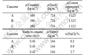
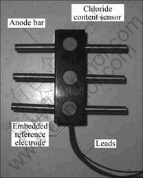
Fig.1 Photo of multi-cell sensors
2.3 Electrochemical test
All the electrochemical measurements were performed with an RST5200 electrochemical system. For each concrete proportion, all the electrochemical parameters were measured six times, and the reported result was an average value of six measurements.
2.3.1 Macrocell current test
Fig.2 shows the typical layout for electrochemical measurements of the macrocell current, Imac (��A), between
Fig.2 Cell configuration of multi-cell sensor systems embedded in concrete for electrochemical measurements
the anodes and cathode. The macrocell currents among anodes (B1-B6) and the accompanying cathode Ti/MMO (mixed metal oxides coated titanium) were recorded at 30 s after coupling.
2.3.2 Chloride ion content test
To obtain the free chloride content from concrete impregnated with a different mass ratio of sodium chloride, the measured potential, �� (mV), using CCS with respect to RE was transformed to a chloride content value according to the following equation, which has been calibrated for several known chloride contents [23]:
��=-78.028��lg[Cl-]+190.75 (1)
2.3.3 Concrete resistance test
In addition, the depth-related concrete resistance surrounding the anode bars was estimated. Fig.3 depicts the equivalent circuit proposed to fit the obtained experimental electrochemical impedance spectroscopy (EIS) data. The response of the embedded anode bars in contact with the concrete is represented by a simple circuit made up of the concrete resistance, Rs (��), in series with a parallel resistance-capacitance (R-C) branch. Furthermore, the low frequency (<1 Hz) time constant represents the charge transfer process, and it is composed of the charge transfer resistance, Rct, in parallel with CPE2; the intermediate-frequency (1 Hz- 1 kHz) time constant CPE1 and film resistance, R1, is usually related to the redox reaction on the anode surface [25].
2.3.4 Corrosion rate test
The linear polarization resistance (LPR, Rp) technique was used. The potential was swept at a scan
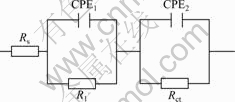
Fig.3 Equivalent circuit of adjacent anode bars for concrete resistance test
rate of 0.2 mV/s from -20 to 20 mV referenced against the free corrosion potential of the steel. Measurement configurations with three electrodes were used, with each anode acting as a working electrode, RE acting as a reference and the Ti/MMO acting as a counter electrode. The Rp results were translated to the corrosion rate Jcorr (��A/cm2) using the Stern and Geary coefficient B:
Jcorr=B/Rp (2)
The value of B is empirically determined and has been measured as 26 mV for active and 52 mV for passive corrosion of steel in concrete [26].
3 Results and discussion
3.1 Determination of macrocell current
Fig.4 depicts the value of Imac as a function of the exposure duration at an ambient temperature of (20��1) ?C and RH of 95% after 24 h curing. As expected, it is found that the concrete with a low content of sodium chloride (0.3%) shows very low macrocell current. On the contrary, the concrete prepared with 0.9% and 2.7% of sodium chlorides (specimens B and C) present a higher
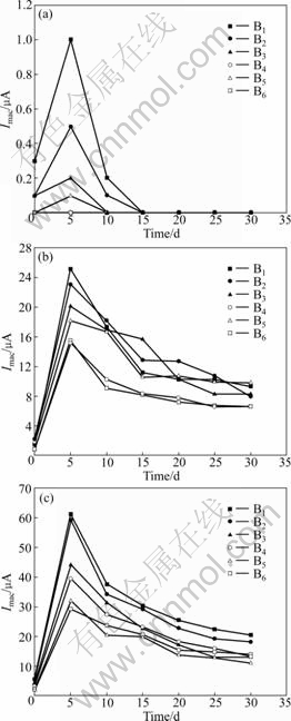
Fig.4 Development of macrocell current Imac for anodes during 30 d exposure: (a) Concrete specimen A; (b) Concrete specimen B; (c) Concrete specimen C
macrocell current of 60 ��A, which may indicate a higher corrosion risk. It can also be observed that the initial period in which chlorides destroy the passive film and the anode bars achieve an active corrosion state is relatively short (about 5 d). Then, the measured Imac significantly decreases as the hydrating and hardening processes of concrete develop because the electrical resistance of the Rs (in Fig.3) between the anode and cathode increases. In addition, Imac at a depth of 0.5 cm (B1) is about 20% higher than that at a depth of 4.5 cm (B3), as shown in Fig.4(a). The macrocell current appears to be affected by the cover depth. Because there is an obvious difference in the concrete resistance and oxygen availability at different cover depths, these parameters may affect the macrocell current. The macrocell current is usually determined by the following equation:
![]() (3)
(3)
where Imac is the macrocell current, ��A; ?�� is the potential difference between the free potential of the anode and cathode, mV; Ran, Rca and Rs are the electrical resistances of the anode bar, cathode and concrete, respectively, ��. For a given macrocell current system, Ran and Rca may stay constant. Thus, the magnitude of the macrocell current mainly depends on the concrete resistance and ?��. Measuring Imac cannot meet the demand for quantitative corrosion monitoring without other parameters, including Rs, humidity, temperature, and chloride content. However, the Imac reflects the comprehensive information of both the cover-zone concrete condition and the electrode potential variation. Thus, it is possible to monitor the critical depth of corrosion and determine the initial time of corrosion by measuring the macrocell current between the anodes and cathode.
3.2 Determining concrete resistance
Fig.5 shows the Nyquist plots for the anode bar B6 in concrete A. The frequency ranges from 50 kHz to 0.01 Hz, and the potential amplitude is 10 mV. As shown in Fig.5, two incomplete semi-arcs exist. Usually, the diameter of the first semi-circle on the curve is considered to correspond to the passive film resistance and capacitance, and the second, large, incomplete one represents the double layer capacitance and Rct. Fig.5 indicates that there is not sufficient curvature at low frequencies because the value of Rct cannot be determined easily from the plots. However, it is still indicated that the resistance of the low frequency arc must be very high and relatively stable as a function of
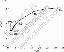
Fig.5 Nyquist plot of correlative anode bar B6 of multi-cell sensor embedded in concrete A
time. Thus, the oxide film that forms as a result of the high pH of the pore solution is intact and binds to the metal well. Only about 25% of the arc is observed for concrete A because the frequency at the top of the arc approximately coincides with the upper frequency limit of the experimental equipment used (approximately 50 kHz). The cusp between 50 kHz and 20 kHz in the Nyquist plot is used to determine the concrete resistance. At this point, the value of Z�� is at a minimum, which is the cutoff frequency (fcut-off). The cut-off frequency for concrete materials has a considerable range and has been observed to range from 100 Hz to 100 kHz [27]. The large range of fcut-off makes single-frequency AC measurements problematic.
However, the impedance curves are likely to demonstrate rectilinear regulation when the frequency is between 20 kHz and 100 Hz, as shown in Fig.5. Because the cusp cannot be determined directly from the plots (especially when fcut-off is more than 50 kHz), the curves need to be extrapolated. For extrapolation, the relationship between the real part Z�� and the imaginary part Z�� in the AC impedance diagram (f��100-2 000 Hz) is as follows:
Z��=aZ��+b (4)
where a represents the slope and b corresponds to the intercept in the impedance diagram. The values of a and b can be calculated from the AC impedance diagram of a correlative anode bar pair (B2 and B6, as shown in Fig.5). Finally, the value of Rs can be calculated. The depth-related resistance values (corresponding to Z��=0) for each concrete sample are given in Table 2.
Table 2 Electrical resistances of concrete measured at ambient temperature of (20��1) ?C and RH of 95%
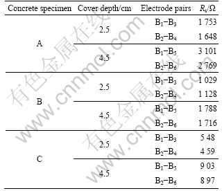
The quality of the concrete specimens can be clearly distinguished by observing the electrical resistance data in Table 2. The concrete resistance level doubles when comparing a depth of 4.5 cm with that of 2.5 cm for all the specimens. Furthermore, it is evident that the electrical resistance of concrete containing more chloride is considerably lower than that with little chloride (specimen A), which results from the increase in conductivity of the concrete as the chloride ion contents increase. The lower chloride content and the thicker cover zone play a significant role in enhancing the corrosion resistant of concrete structures. Moreover, by taking into account of the depth-related oxygen availability in the concrete, the corrosion rate of steel in concrete decreases as the concrete resistance increases based on the quality and cover-zone depth for normal exposure conditions [22].
3.3 Corrosion rate of anode bars
According to some researches, corrosion current densities over 1 ��A/cm2 are identified as high corrosion risk, and corrosion current densities below 0.1 ��A/cm2 are characterized as passive corrosion in the system [26]. Accordingly, the value of the Stern-Geary coefficient B was chosen to be 52 mV in specimen A, and 26 mV in specimens B and C. The variation of the free chloride content of the specimens according to the cover depth and the corrosion rate of anode bars embedded in the specimens are given in Table 3.
As shown in Table 3, the average free chloride content at different depth of specimens A, B and C are
Table 3 Corrosion rate of anode bars and chloride contents measured at ambient temperature of (20��1) ?C
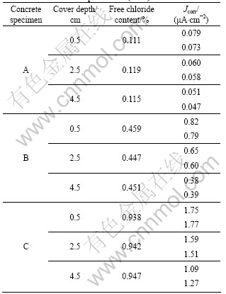
about 0.11%, 0.45% and 0.94%, respectively. However, only free chloride ions influence the corrosion process. Thus, the difference between the chloride contents obtained from the water soluble method (ASTM C1218) and the CCS in different concretes is shown in Fig.6. The measured values by CCS show excellent agreement with the results from the water soluble method, which indicates that the measured chloride contents by CCS can be used to determine the free chloride content.

Fig.6 Chloride contents measured by CCS and water soluble method in different concrete specimens
It is well known that values of free chlorides over 0.4% in the cement content lead to localized corrosion of the steel because the protective layer ruptures [28]. This predictable rule is observed in the corrosion rate estimations. The lowest Jcorr values in specimen A indicate that adding 0.3% chlorides will not induce serious corrosion in the present sensor system. However, with regard to the Jcorr values in specimen B, a difference of more than 10 times is observed compared with the values observed in specimen A. For the highest mixed chlorides, specimen C, the highest corrosion rates are observed. The results show that the measured corrosion rates increase as the chloride content increases, which occurs because the chloride ions can combine with ferrous ions to form a water soluble product that can also accelerate the corrosion process [24]. Thus, it can be concluded that the concrete service conditions, including concrete resistance and chloride content surrounding the steel surface, play a decisive role in the corrosion behavior of the steel electrode. This result can be explained logically by the optimal combination of the sufficient ingressive ionic conductivity and the availability of oxygen in the chloride-contaminated concrete structures [29].
3.4 Modeling
Based on the present multi-cell sensor, the corrosion rate of anode bars in MCS can be determined by the linear polarization resistance (LPR) method if necessary. However, it is worth noting that the corrosion rates of structural steel rebars in service should be measured and evaluated simultaneously so that the data provided by the MCS system are more meaningful. Unfortunately, steels used in concrete structures usually have a complex structure, e.g., the effective surface area of rebars is unknown, and they are usually disturbed by interference current from either the ground or human actions. Thus, attempts to quantify the corrosion rate of structural steel rebars using traditional electrochemical technologies have met both theoretical and empirical problems [18].
For convenience, using a prediction model to evaluate the corrosion rate of structural steels in service described by LIUS and WEYERS [21] is proved to be more suitable. The model is deduced from the regression results of the corrosion database (2 927 measurements from a series of seven chloride-contaminated specimens with up to five years of outdoor exposure) and is written as
ln (1.08Jcorr)=8.37+0.618 ln(1.69[Cl-])-303 4/T- 0.000 105Rc+2.32t-0.215 (5)
where Jcorr is the period-dependent corrosion rate, ��A/cm2; [Cl-] is the free chloride content, kg/m3; T is the temperature at a certain depth of the steel surface; Rc is the cover-zone concrete resistivity, ����cm; t is the corrosion time, a. The regression model details all the circumstances, such as different environment temperature and relative humidity, and describes the full process of period-dependent corrosion rate variation as the chloride content increases in concrete. Accordingly, the model provides an average annual corrosion rate but fails to obtain an instantaneous corrosion rate of steel bars. However, it is cumbersome in practical applications. Consequently, simplifying Eq.(5) is critical. An assumption to solve this problem is as follows. The proposed model is time-independent, and the temperature is the same for all the measured periods, 20 ?C, based on the condition-fixing agreement. Then, the parameters T and t can be neglected, and the model results are presented for the same two parameters. Consequently, based on Eq.(5), a statistical analysis is performed and a simple non-linear model is put forward as
ln Jcorr=K0+Fclln [Cl-]-FsRs (6)
where Jcorr is the instantaneous corrosion rate, ��A/cm2; Rs is the cover-zone concrete resistance, ��; K0 is the compensation factor, and Fcl and Fs are the impact factors of the chloride ion concentration and the concrete resistance, respectively. The values of the compensation and impact factors in the prediction model could be defined by the measured values of specimens A and C listed in Table 2 and Table 3. Consequently, the prediction model that characterizes the corrosion rate based on the obtained cover-zone parameters is presented as
ln Jcorr=4.55+0.78ln [Cl-]-0.73��10-3Rs, R2=0.91 (7)
Compared with the model in Ref.[22], the instantaneous corrosion rate of the steel in the chloride-contaminated concrete is a function of the concrete chloride content at the rebar depth and the electrical resistance of the cover-zone concrete. According to this correlation, the values of the instantaneous corrosion rate of the structural steels can be calculated. Note that the validity of this model can be checked using both the measured corrosion rate (MR) from specimen B and the calculated corrosion rate (CR) according to Eq.(7). Fig.7 shows the values of MR and CR and the cover concrete resistance for specimen B with a free chloride content of 0.45%.
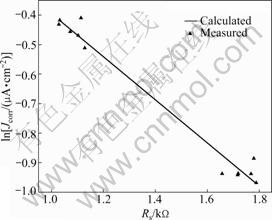
Fig.7 ln Jcorr of anode bars embedded (free chloride content 0.45%) in concrete B plotted against cover concrete resistance
In Fig.7, there is a good agreement between the model prediction and experimental result. The calculated ln Jcorr values decrease rapidly as Rs increases. In this study, the actual measurements and prediction models are based on concrete specimens with different free chloride contents; thus, the experimental results are only a linear interpolation. It is also important to note that material properties in concrete are seldom linearly related [30], so the model will not predict corrosion rates completely accurately. However, compared with the existing electrochemical test methods, the instantaneous corrosion rate calculated from the present model is more accurate by 10%-50% [16]. In short, there will be some difference between the results of prediction model and field monitoring due to different compositions of concrete.
Further, because the model is developed from mixed-chloride concrete, some adjustments are needed to estimate the corrosion rate for on-site concrete structures where chloride ions usually diffuse into the concrete. The difference in chloride concentration in concrete pore solutions between mixed-chloride concrete and the on-site concrete needs to be further investigated. Theoretically, the concentration can be deduced from the measured value using the depth-related CCS in the cover-zone concrete. Another point worth emphasizing is that this model is developed for a given constant temperature and relative humidity, and further work is needed to develop a long-term temperature sensor and effective humidity sensor. In general, some approaches to monitor exposure conditions may improve the predication of the instantaneous corrosion rate in the future.
4 Conclusions
1) A new multi-cell sensor system embedded in the chloride-contaminated concrete was developed to monitor the service condition of the reinforced concrete structure continuously. This system can provide accurate measurements of the macrocell current, chloride ion content, electrical resistance of concrete, and corrosion rate of reinforced structure.
2) The macrocell current increases as the proportion of chloride increases, which indicates a higher corrosion risk in the reinforced structure. However, while the macrocell current does not meet the requirement for quantitive corrosion monitoring, it is a good method to monitor the critical depth of corrosion and the initial time of corrosion. The test data based on electrochemical impedance measurements prove that a higher chloride ion content and thinner concrete cover result in lower electrical resistance and higher corrosion risk.
3) By neglecting temperature and time, a simple prediction model was established to clarify the relationship among the instantaneous corrosion rate of steels, concrete resistance and chloride content. This new multi-cell system can serve as a corrosion risk- monitoring device by providing substantial information that includes both concrete properties and the corrosion rate of structural steel.
References
[1] VERA R, VILLARROEL M, CARVAJAL A M, VERA E, ORTIZ C. Corrosion products of reinforcement in concrete in marine and industrial environments [J]. Materials Chemistry and Physics, 2009, 114(1): 467-474.
[2] SOLEYMANI H R, ISMAIL M E. Comparing corrosion measurement methods to assess the corrosion activity of laboratory OPC and HPC concrete specimens [J]. Cement and Concrete Research, 2004, 34(11): 2037-2044.
[3] McCARTER W J, VENNESLAND ?. Sensor system for use in reinforced concrete structures [J]. Construction and Building Materials, 2004, 18(6): 351-358.
[4] XU Jin-xia, JIANG Lin-hua, WANG Jing-xiang. Influence of detection methods on chloride thresthold value for the corrosion of steel reinforcement [J]. Construction and Building Materials, 2009, 23(5): 1902-1908.
[5] BASHEER P A M, GILLEECE P R V, LONG A E, McCARTER W J. Monitoring electrical resistance of concretes containing alternative cementitious materials to assess their resistance to chloride penetration [J]. Cement & Concrete Composites, 2002, 24(5): 437-449.
[6] MONTEMOR M F, ALVES J H, SIM?ES A M, FERNANDES J C S, LOUREN?O Z, COSTA A J S, APPLETON A J, FERREIRA M G S. Multiprobe chloride sensor for in situ monitoring of reinforced concrete structures [J]. Cement & Concrete Composites, 2006, 28(3): 233-236.
[7] de VERA G, CLIMENT M A, ANTON C, HIDALGO A, ANDRADE C. Determination of the selectivity coefficient of a chloride ion selective electrode in alkaline media simulating the cement paste pore solution [J]. Journal of Electroanalytical Chemistry, 2010(1/2): 43-49.
[8] HANSSON C M, POURSAEE A, LAURENT A. Macrocell and microcell corrosion of steel in ordinary Portland cement and high performance concretes [J]. Cement and Concrete Research, 2006, 36(11): 2098-2102.
[9] SCHIE��L R M. Macrocell sensor systems for monitoring of the corrosion risk of the reinforcement in concrete structures [J]. NDT&E International, 2001, 34(6): 435-442.
[10] ELSENER B. Macrocell corrosion of steel in concrete-implications for corrosion monitoring [J]. Cement & Concrete Composites, 2002, 24(1): 65-72.
[11] CLIMENT-LLORCA M A, VIQUEIRA-P?REZ E, L?NEZ-ATALAYA M M, Embeddable Ag/AgCl sensors for in-situ monitoring chloride contents in concrete [J]. Cement and Concrete Research, 1996, 26(8): 1157-1161.
[12] SOLEYMANI H R, ISMAIL M E. Comparing corrosion measurement methods to assess the corrosion activity of laboratory OPC and HPC concrete specimens [J]. Cement and Concrete Research, 2004, 34(11): 2037-2044.
[13] LI S Y, KIM Y G, JUNG S, SONG H S, LEE S M. Application of steel thin film electrical resistance sensor for in situ corrosion monitoring [J]. Sensors and Actuators B, 2007, 120(2): 368-377.
[14] CAO J Y, CHUNG D D L. Electric polarization and depolarization in cement-based materials, studied by apparent electrical resistance [J]. Cement and Concrete Research, 2004, 34(3): 481-485.
[15] POLDER R B. Test method for on site measurement of resistivity of concrete��A RILEM TC-154 technical recommendation [J]. Construction and Building Materials, 2001, 15(2/3): 125-131.
[16] WOJTAS H. Determination of corrosion rate of reinforcement with a modulated Guard Ring electrode; analysis of errors due to lateral current distribution [J]. Corrosion Science, 2004, 46(7): 1621-1632.
[17] ATKINS C P, CARTER M A, SCANTLEBURY J D. Sources of error in using silver/silver chloride electrodes to monitor chloride activity in concrete [J]. Cement and Concrete Research, 2001, 31(8): 1207-1211.
[18] FELIU S, GONZ?LEZ J A, MIRANDA J M, FELIU V. Possibilities and problems of in situ techniques for measuring steel corrosion rates in large reinforced concrete structures [J]. Corrosion Science, 2005, 47(1): 217-238.
[19] LEELALERKIET V, KYUNG J W, OHTSU M, YOKOTA M. Analysis of half-cell potential measurement for corrosion of reinforced concrete [J]. Construction and Building Materials, 2004, 18(3): 155-162.
[20] LIU You-ping, WEYERS R E. Comparison of guarded and unguarded linear polarization CCD devices with weight loss measurements [J]. Cement and Concrete Research, 2003, 33(7): 1093-1101.
[21] LIUS T, WEYERS R W. Modeling the dynamic corrosion process in chloride contaminated concrete structures [J]. Cement and Concrete Research, 1998, 28(3): 365-379.
[22] ZHENG Yi, LIU Ming, ZHOU Jing-hai, WANG bing. Bonding stress-slip constitutive behavior between bars and grout concrete [J]. Journal of Central South University of Technology, 2009, 16(5): 841-844.
[23] ZHAO Wei-xuan, LU shuang, L? Jian-fu, BA Heng-jing, WANG Li. Monitoring chloride concentrations in concrete pore solutions using silver/nano-silver chloride sensors [J]. Journal of Wuhan University of Technology: Mater Sci Ed, 2009, 89(24): 214-217.
[24] LU Shuang, WANG Zheng, BA Heng-jing, YANG Ying-zi. Preparation of Ti/MnO2 reference electrode and its application in concrete structures [J]. Journal of Wuhan University of Technology: Mater Sci Ed, 2009, 89(24): 161-165.
[25] SAGUES A A, KRANC S C, MORENO E I. Evaluation of electrochemical impedance with constant phase angle component from the galvanostatic step response of steel in concrete [J]. Electrochimica Acta, 1996, 41(7/8): 1239-1243.
[26] BARONIO G, BERRA M, BERTOLINI L, PASTORE T. Steel corrosion monitoring in normal and total-lightweight concretes exposed to chloride and sulphate solutions. 2: Polarisation resistance measurements [J]. Cement and Concrete Research, 1996, 26(5): 691-696.
[27] ANDRADE C, SOLER L, ALONSO C, NOVOA X R, KEDDAM M. The importance of geometrical considerations in the measurement of steel corrosion in concrete by means of AC impedance [J]. Corrosion Science, 1995, 37(12): 2013-2023.
[28] ALONSO A, ANDRADE C, CASTELLOTE M, CASTRO P. Chloride threshold values to depassivate reinforcing bars embedded in a standardized OPC mortar [J]. Cement and Concrete Research, 2000, 30(7): 1047-1055.
[29] CORREIA M J, PEREIRA E V, SALTA M M, FONSECA I T E. Sensor for oxygen evaluation in concrete [J]. Cement & Concrete Composites, 2006, 28(3): 226-232.
[30] VERA R, VILLARROEL M, CARVAJAL A M, VERA E, ORTIZ C. Corrosion products of reinforcement in concrete in marine and industrial environments [J]. Materials Chemistry and Physics, 2009, 114(1): 467-474.
Foundation item: Project(200632800003-11) supported by Western Communications Construction Scientific and Technological Project in China
Received date: 2009-12-21; Accepted date: 2010-07-05
Corresponding author: LU Shuang, PhD candidate; Tel: +86-451-86281118; E-mail: hitlu@126.com
