

ARTICLE
J. Cent. South Univ. (2019) 26: 1306-1326
DOI: https://doi.org/10.1007/s11771-019-4089-4

Analysis of behaviour of computational model to evaluate performance of heat pipe containing nanofluids
Rodrigo Vidonscky PINTO, Fl��vio Augusto Sanzovo FIORELLI
University of S o Paulo, Escola Polit��cnica, Mechanical Engineering Department, Avenida Professor Mello Moraes, 2231, 05508-030, So Paulo (SP), Brazil
 Central South University Press and Springer-Verlag GmbH Germany, part of Springer Nature 2019
Abstract:
Application of nanofluids in heat pipes usually presents satisfactory experimental results regarding a thermal resistance reduction of the heat pipe. However, the existing computational studies connecting heat pipes and nanofluids lack a deeper discussion regarding the validity of the models currently used for representing the behaviour of a nanofluid in a heat pipe, particularly for unusual base fluids and nanoparticles such as carbon nanotubes or ethylene glycol. Thus, this comparative study presents the results of a set of computational simulations using pre-established equations for modelling a nanofluid in a heat pipe with experimental data from the literature. The results show agreement with the expected behaviour qualitatively and the presented maximum variations between 1.5% and 23.9% in comparison to the experimentally measured average temperatures. Also, the experimentally obtained temperature distribution of a heat pipe could not be reached numerically only with the use of adequate thermal properties, indicating that the boiling phenomenon is more complex than the current model used for computational simulations. Moreover, the existence of an optimal particle volume fraction for using nanofluids in this application could be observed by combining different properties models.
Key words:
heat pipe; nanofluid; computational analysis; particle volume fraction��
Cite this article as:
Rodrigo Vidonscky PINTO, Fl��vio Augusto Sanzovo FIORELLI. Analysis of behaviour of computational model to evaluate performance of heat pipe containing nanofluids [J]. Journal of Central South University, 2019, 26(5): 1306�C1326.
DOI:https://dx.doi.org/https://doi.org/10.1007/s11771-019-4089-41 Introduction
Recent experimental studies reveal that the results from the combination of nanofluids and heat pipes are usually desirable regarding heat transfer, so that this application has excellent perspectives. By introducing such nanofluids, the results present a very significant enhancement in the heat transfer that occurs at the existing phase change phenomenon in those heat pipes.
A heat pipe is a tube made of thermal conductor material, containing a porous material of annular format and a working fluid confined inside it. This porous material (called wick) covers the inner surface of the tube along its length, while the working fluid fills the space inside the porous material as a saturated liquid and the rest of the heat pipe interior as a saturated gas. This device operates as a passive heat pump, extracting heat from a hot part, transporting this heat through its inner structure (with no use of energy) and rejecting this heat to a cold part. The heat is responsible for the phase change processes of the working fluid inside the heat pipe, providing high heat transfer coefficients and very high heat transmission efficiency.
Nanofluids are obtained by mixing a base fluid and nanoparticles of a solid material dispersed in suspension along the base fluid. The most common base fluids used in the composition of a nanofluid are water, oil, ethylene glycol, or even unusual heat transfer fluids, such as kerosene [1]. Also, several solid materials can be used in the composition of a nanofluid, such as metals [2], oxides [3, 4] or even carbonic structures such as diamonds or carbon nanotubes [5, 6]. These particles have medium sizes under 100 nm and are uniformly dispersed in the fluid. Some typical nanofluids are ethylene glycol with copper nanoparticles and water with copper oxide nanoparticles among others.
The review published by LIU et al [7] presented experimental results obtained for the heat pipe and nanofluid combination applied to several kinds and formats of heat pipes, and different nanofluids with different mass fractions and multiple combinations of materials used for the base fluid and the nanoparticles. In this study, 40 different combinations were analyzed, and only four of these combinations presented a lower performance than using the base fluid alone in the heat pipe. In some of the positive cases, the thermal resistance of the heat pipe was reduced to less than a half of the original thermal resistance. This behaviour means that by defining a fixed temperature difference, more than twice of the original heat can be transferred by this heat pipe. Newer reviews were published by BUSCHMANN [8] and SURESHKUMAR et al [9], and also obtained similar results regarding the heat transfer performance.
The existing analytical studies associating nanofluids and heat pipes are still considerably rare and focused on limited practical applications. Moreover, most numerical predictive models currently used for defining the physical behaviour of the nanofluids focus on the convection problems [10], neglecting phase change applications, such as a heat pipe. The boiling phenomenon occurring into a heat pipe still present many questions regarding the influence of the several physical mechanisms that have constantly been studied and defined as relevant to the heat transfer enhancement obtained using nanofluids under boiling conditions, especially concerning non-conventional materials such as ethylene glycol or carbon nanotubes and notably lacking a further analysis of the equations currently used for the computational modeling of the phase change of the nanofluid into the heat pipe.
Hence, the main contribution presented by the current work consists of evaluating one of the models currently used for computationally analyzing the thermal and hydrodynamic behaviour of a heat pipe containing a nanofluid in its interior. This model was proposed by MAHJOUB et al [11] for a heat pipe containing a pure fluid and used by GAVTASH et al [12] for the computational simulation of a heat pipe containing nanofluids composed of water and metallic or oxide nanoparticles. This evaluation consists in applying this model to a computational simulation using experimental data of several other experimental studies associating heat pipes and unusual nanofluids, such as nanofluids containing carbon nanotubes (CNT), or using ethylene glycol as a base fluid. These nanofluids were selected to expose some of the most notable results from recent experimental studies. As a second contribution, this study indicates the importance of the correct definition of the nanofluids properties in computational simulation, as well as the sensitivity of the properties obtained by using different models considering different phenomena. For this, a parametric analysis involving the use of different equations for evaluating the main properties of the nanofluids is performed. This parametric analysis indicates the significance of each of the physical phenomenon considered in the evaluation of the behaviour of a nanofluid, as well as the range of significance of the equations used to define each property of the nanofluid in a computational simulation. Finally, the effect obtained by the extrapolation of these equations used for defining the physical properties of the nanofluids to nanofluids containing several volume fractions of nanoparticles is also investigated. This seeks to expose a behaviour obtained experimentally, which consists in the existence of an intermediate value of the volume fraction of nanoparticles in a nanofluid in which the thermal performance of the heat pipe is optimal, so that in higher volume fractions, the thermal performance begins to deteriorate by viscous effects.
2 Analysis
The modelling of the thermal behaviour of a heat pipe containing conventional working fluids has a significant amount of works involving analytical and experimental solutions. Regarding experimental solutions, the work by ZERBINI [13] analyzed heat pipes at moderate temperatures, evaluating values for the effective thermal conductivity of a heat pipe. The results presented effective thermal conductivities up to 27 times higher than the thermal conductivity obtained from a pure copper bar.
Among the analytical solutions, the work by MAHJOUB et al [11] proposed a numerical solution for the working fluid flow along the entire heat pipe. In this work model, the mass, energy, and motion conservation equations were combined with the finite volume method applied to cylindrical coordinates using the software ANSYS FLUENT to obtain the solution of the resulting system of equations.
The mathematical model used in the current work is based on the model of these authors. This model divides the heat pipe into three different sections: evaporator section, adiabatic section, and condenser section. It considered that the flow is steady, incompressible and laminar, due to the nature of the analysis and the geometry of the problem, and that there is angular symmetry. It also assumed for simplicity that the steam region fluid does not have contact with the porous region fluid of the heat pipe. Also, some assumptions usually adopted in recent studies regarding nanofluids, such as the adoption of corrections of the Navier Stokes equation in order to consider effects such as thermal dispersion [14], the viscosity reduction with increasing shear rate [15], the separation of the thermal conductivity of the nanofluid in a static and a Brownian component [16] and the introduction of two-phase mixture models with drift velocity for the nanofluid [17�C19], were not adopted in this model.
Thus, the equations that describe the mass conservation, the motion conservation in z and r directions and the energy conservation in the steam region of the heat pipe are respectively:
 (1)
(1)
 (2)
(2)
 (3)
(3)
 (4)
(4)
At the porous wick region of the heat pipe, the motion and energy conservation equations for the fluid in the liquid state are based on the on the Darcy��s Law and on the simple homogeneous model [20] to describe the fluid flow using temperature-independent properties with no slip between the base fluid and the nanoparticles, uniformly distributed nanoparticles along the base fluid and hydrodynamic and thermal equilibrium between the two phases of the nanofluid:

 (5)
(5)

 (6)
(6)
 (7)
(7)
where kef represents the effective thermal conductivity of the wick filled with liquid. In this work, this conductivity was obtained by associating liquid conductivity kl, wick conductivity kmp and the porosity of the wick �� such as:
 (8)
(8)
Also, it is necessary to introduce the thermal effect caused by the phase change of the working fluid. Hence, it was adopted terms representing a source and a sink of heat in the evaporator and in the condenser section, whose values are:
 (9)
(9)
 (10)
(10)
 (11)
(11)
At the interface between the heat pipe wall and the wick, heat conduction between the two regions is adopted, represented by:
 (12)
(12)
Finally, on the heat pipe walls, the heat conduction equation in cylindrical coordinates is defined as:
 (13)
(13)
The associated boundary conditions adopted for the solution of the heat transfer problem were: At the liquid-steam interface, the phase change of the fluid is responsible for motion, suctioning the fluid from one of the interfaces and expelling the fluid to the other region that forms the interface. Representing this phenomenon requires the introduction of suction and expelling velocities at the liquid-steam interface in the steam region:
 (14)
(14)
 (15)
(15)
 (16)
(16)
and in the wick/liquid region:
 (17)
(17)
(18)
 (19)
(19)
At the external surface of the heat pipe walls, the boundary conditions correspond to the heat introduction at the evaporator section and to the heat extraction at the condenser section:
Evaporator:
 (20)
(20)
Adiabatic:
 (21)
(21)
Condenser:
 (22)
(22)
Finally, in all regions, the longitudinal edge of the heat pipe presents a boundary condition equivalent to an adiabatic wall:
 (23)
(23)
 (24)
(24)
Regarding nanofluids, it must be noticed that the correct characterization of the nanofluids properties is a key aspect of the simulation of its thermal behaviour, once the homogeneous model uses those properties as the main parameters to distinguish the nanofluid from the base fluid. There are thus many works searching to create better mathematical models in order to enable the correct representation of the behaviour of the nanofluid main physical properties.
The presented model basically requires four properties in order to define the fluid contained in the heat pipe, namely density (or specific mass), dynamic viscosity, specific heat and thermal conductivity. Those properties have been vastly researched by several studies among the literature [20] such that most of the physical effects introduced by the nanoparticles of a nanofluid can be considered to define these properties.
For determining the density of a standard nanofluid, most existing works adopt the same model used for microscopic particles mixtures and assume that a nanofluid density is equivalent to the density of a simple mixture between a fluid and solid particles. The corresponding equation is presented in Ref. [21] for any liquid containing solid particles dispersed in this fluid. The same equation is presented in Refs. [12, 22, 23].
As regards the specific heat of the nanofluids, O��HANLEY et al [24] present a model capable of predicting this property of a nanofluid. This model is based on the hypothesis that there is a thermal balance between the nanoparticles and the base fluid in a nanofluid. XUAN et al [14] also used an adapted form of this model to determine the specific heat of a generic nanofluid in their study.
For calculating the dynamic viscosity of different nanofluids, the review studies of MISHRA et al [25] and HALELFADL et al [26] sought to gather several existing models. The models presented in these studies consist in approaches to different situations in which one or more characteristics directly influence the determination of the nanofluid viscosity. Those characteristics can be defined by properties of the nanofluid components, such as the base fluid viscosity, properties of the nanofluid composition, such as the volume fraction of nanoparticles, or even characteristics obtained at the nanofluid synthesis, such as the agglomeration radius of nanoparticles. The most relevant models for the present work are the models of EINSTEIN [27], NIELSEN [28], BATCHELOR [29], BRINKMAN [30], NGUYEN et al [31], PAK et al [21], CHOW [32], MARON et al [33], BRENNER et al [34], and KRIEGER [35].
Regarding the thermal conductivity, a great number of studies and models were proposed to determine this property in nanofluids. These models have a direct relation with the physical characteristics of the nanofluids components, such as the thermal conductivity of the base fluid and of the nanoparticles. From studies by LAMAS et al [36], SUNDAR et al [37], PASTORIZA- GALLEGO et al [38], KWAK et al [39], LIU et al [40] and YU et al [41], the most relevant models for the present work were gathered: HAMILTON et al [42], NAN [43], XUE [44], WASP [45], CHEN et al [46], JEFFREY [47], YU et al [48], TURIAN [49], and MURSHED [50].
Several experimental studies involving heat pipes and nanofluids can be found in these works, involving a wide range of nanoparticles used to compose to these nanofluids and several configurations of heat pipes. However, when concerning some specific nanofluid compositions, such as nanofluids containing ethylene glycol as a base fluid or nanofluids containing carbon nanotubes as nanoparticles, these studies are limited to a small number of cases, even with promising results.
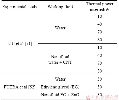
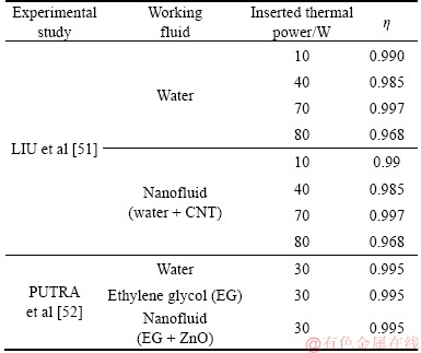
As regards heat pipes containing nanofluids with carbon nanotubes (CNT) nanoparticles, the applications are usually restricted to two-phase closed thermosyphons. However, this study will focus on studies presenting heat pipes containing a wick structure. The most relevant study with these characteristics is the study by LIU et al [51].
This study evaluated the improvement in the thermal performance of a heat pipe with the introduction of a carbon nanotube-based nanofluid, also obtaining an optimal carbon nanotube concentration to achieve maximum heat transfer. It used a copper heat pipe with axial microgrooves containing a nanofluid composed of water and carbon nanotube nanoparticles dispersed in different mass fractions (between 1% and 2.5%) along the base fluid. It was also defined that this heat pipe would be subjected to a heat flux in the evaporator section between 10 W and 80 W as the primary boundary condition.
The results from the experimental analysis of this heat pipe containing a nanofluid with a mass fraction of 2% were compared to the results from using only water and are depicted in Figure 1(a). This figure shows that the effect of replacing the base fluid with a nanofluid is much greater for higher amounts of heat applied to the heat pipe so that the presence of the nanoparticles significantly reduces the mean temperature difference between the evaporator and the condenser sections of the heat pipe. Moreover, the temperature change is notably more significant in the evaporator section than in the condenser section.
The thermal resistances obtained for a wide range of heat fluxes can be observed in Figure 1(b). Both global thermal resistance and operation range of the heat pipe (defined as the range between the higher thermal resistances associated to low heat fluxes and resulting from the low boiling rates, and the higher thermal resistances associated to high heat fluxes and resulting from the dryout phenomenon) are enhanced.
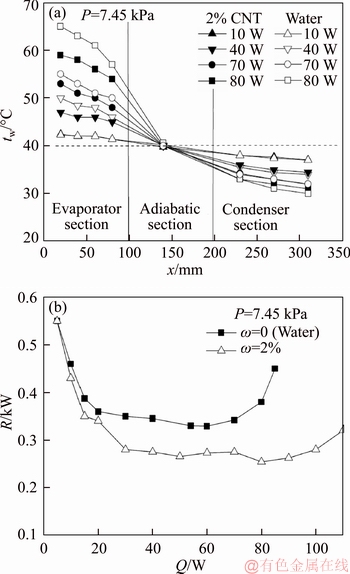
Figure 1 Temperature distributions (a) and thermal resistance (b) of a heat pipe containing water or CNT nanofluid for different heat fluxes (LIU et al [51])
The authors concluded that four main reasons justify the heat transfer enhancement obtained. The first reason is the simple thermal conductivity enhancement obtained by mixing solid particles in a fluid. The second reason is the density enhancement obtained by mixing solid particles in a fluid. The third reason consists in reducing the contact angle between the solid surface and the fluid caused by the deposition of solid particles along the heating surface. The fourth reason is the formation of microscale turbulence due to the Brownian motion of nanoparticles along the nanofluid.
Regarding heat pipes containing nanofluids with ethylene glycol as a base fluid, there are still few studies involving a limited number of nanoparticles applied to these nanofluids. The main study in this area is by PUTRA et al [52], which seeks to relate the enhancement obtained in the thermal performance of a heat pipe containing wicks made of screen meshes and nanofluids containing water or ethylene glycol as a base fluid and nanoparticles of Al2O3, TiO2 and ZnO in different volume fractions.
The use of those nanoparticles enabled significant enhancements in the thermal conductivity of the base fluid. Figure 2(a), adapted from PUTRA et al [52], shows the behaviour of the ratio between the thermal conductivity of the resulting nanofluids and the thermal conductivity of the liquid ethylene glycol, measured experimentally for different volume fractions of nanoparticles in the nanofluid.
The thermal behaviour obtained by applying 30 W of thermal power at the evaporator section of the heat pipe studied using different working fluids (such as water, ethylene glycol and nanofluids with 5% volume fraction) can be observed in the temperature distributions presented in Figure 2(b), adapted from PUTRA et al [52]. The use of any composition of nanofluids resulted in a significant reduction of the maximum temperature obtained at the evaporator section. This means that for a fixed heat rate introduced in the heat pipe, the addition of nanofluids allows the heat pipe to operate in lower temperature ranges in all cases, reducing the thermal resistance of the whole heat pipe.
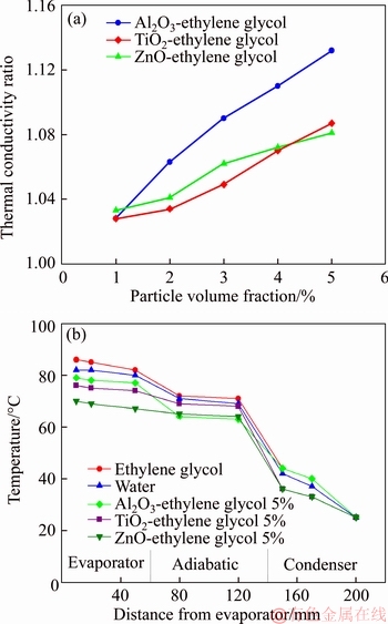
Figure 2 Thermal conductivity enhancement of nanofluids containing ethylene glycol (a) and temperature distributions (b) of a heat pipe containing different nanofluids (adapted from PUTRA et al [52])
The temperature distributions from Figure 2(b) also show that, at the condenser end of the heat pipe, all the temperatures remain constant for all the situations and equal nearly 25 ��C. The experimental conditions of this study are assumed to define that this temperature remains constant due to the experimental set.
At the end of this study, the use of nanofluids was concluded to be responsible for forming a thin layer on the surface of the wick, and this layer enabled the enhancement of the capillary transport along the heat pipe. The heat transfer could thus be higher than the expected by the simple enhancement of the thermal conductivity.
3 Methodology
The studied cases presented in Table 1 were selected from the works presented to represent a wide range of situations with the computational approach. The implementation of the desired computational models can be divided into three main phases. The first phase is the creation of the computational grid. The second phase consists in the proper determination of the physical properties of each section of the implemented domain, in order to correctly represent the corresponding materials used in each heat pipe studied. Finally, the third phase corresponds to applying the representative initial and boundary conditions of the problem at the calculation domain to represent the physical phenomena that define the problem.
Table 1 Selected experimental cases
For constructing the computational grid, software ICEM CFDwas selected. A pair of two-dimensional meshes was constructed in the present work, since every heat pipe studied presents angular symmetry all along its length.
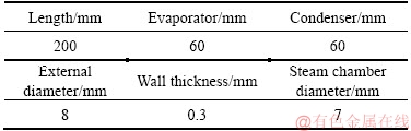
The dimensions presented in Table 2 correspond to the dimensions used in creating a representative geometric model for the heat pipe containing a rectangular micro-grooved wick studied in Ref. [51].
Similarly, the dimensions presented in Table 3 correspond to the dimensions used to create a representative geometric model for the heat pipe, which contained a wrapped screen-meshed wick studied in Ref. [52].
Table 2 Representative dimensions used for generating computational mesh of heat pipes used in Ref. [51]
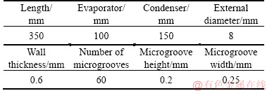
Table 3 Representative dimensions used for generating computational mesh of heat pipes used in Ref. [52]
These meshes were created using the automatic routine for mesh construction based on the problem geometry, contained in the ICEM CFD. It was assumed that there is rotational symmetry along the heat pipe, enabling the construction of a mesh containing just half the size of the full heat pipe.
The smaller dimension used in these computational meshes was defined as 0.05 mm (corresponding to 25% of the minor order of magnitude of these heat pipes) to obtain the desired precision. All the elements created presented 100% quality, rated by the ICEM CFD.
The conversion of the mesh to the analysis software ANSYS CFXrequired the mesh to be three-dimensionalised. To avoid spatial effects, the angular dimension must assume a small dimension and must have symmetry applied to both transversal faces of the three-dimensional model. A dimension of 1 mm was adopted in the present study so that this behaviour could be achieved.
The definition of the physical properties of each section of the heat pipes is obtained dividing the materials used in the construction of the heat pipe in three categories. These categories are heat pipe wall, wick, and working fluid.
On the heat pipe wall, a material able to contain the working fluid under pressure inside the heat pipe is necessary. Simultaneously, this material must have a high enough thermal conductivity for the heat received by the heat pipe to be transmitted to the working fluid efficiently. A material that matches these specifications is copper, which was used by each heat pipe for this application.
Copper is a widely used material in engineering applications for its attractive physical properties, such as thermal conductivity and electrical conductivity. At 300 K, copper has a specific heat of 0.385 kJ/(kg��K), specific mass of 8930 kg/m3and thermal conductivity of 401 W/(m��K).
The wick used in the heat pipe presented in Ref. [51] consists of a series of rectangular grooves manufactured on the internal wall of the heat pipe. Copper is also the base material defined for this region.
The properties associated to the porosity of the wick could be defined by the geometric dimensions of the rectangular grooves composing the wick. From Table 2, the empty space volume of the wick can be calculated as 1050 mm3. Considering that the full volume of the wick is 1451.4 mm3, the porosity of this wick is defined as 0.723.
Also, using a procedure defined by CHI [53] and the dimensions of Table 2, the wick permeability can be obtained by defining the hydraulic radius Rh and the aspect ratio AR of the rectangular grooves. These parameters can be calculated as:
 (25)
(25)
 (26)
(26)
so that w is the width of the rectangular grooves and �� is the depth (or height) of the rectangular grooves.
The value of the permeability obtained by LIU et al [51] for heat pipe wick can be calculated as:
 (27)
(27)
so that flRel is directly related to the aspect ratio of the rectangular grooves. The value obtained for this permeability is 2.283��10�C9m2.
Similarly, the wick used in the heat pipe presented in Ref. [52] consists of a wrapped screen mesh, made of single-plaited stainless steel. Stainless steel is a steel alloy composed of iron and different proportions of chromium, which is responsible for turning the steel stainless in proportions above 12%. The corrosion resistance of this composition permits using this material in applications involving direct contact with oxidant fluids, such as in a heat pipe. The physical properties can vary according to the chromium proportion. As a reference, it can be attributed the average properties a density of 7955 kg/m3, a specific heat of 0.510 kJ/(kg��K) and a thermal conductivity of 15.5 W/(m��K). PUTRA et al [52] also define the wire diameter of the screen as equal to 56.5 ��m and the mesh number (N) as equal to 6.742 plaits of wires per mm.
When determining the porosity of wicks made of wrapped screens, CHI [53] associates the porosity with the wire diameter and the mesh number:
 (28)
(28)
The value of the porosity of the wick used in the heat pipe in Ref. [52] is hence 0.686.
With this value, the value of the permeability can be determined using the modified equation of Blake-Kozeny, defined for wrapped screen meshes and provided by CHI [53]:
 (29)
(29)
Applying the properties of this wick, the value for this permeability is 8.558��10�C11m2.
In the heat pipe based in Ref. [51], the working fluid consists of water or nanofluids containing water as a base fluid. The reference properties used for the liquid water are widely known in the literature, while the adoption of properties for the gaseous water requires assuming a model to correctly describe its behaviour. In the present work, it was assumed that the gas state is not near the critical point of the water, nor are there gas-liquid interactions, according to the assumptions in the model of MAHJOUB et al [11]. The estimates of this material properties were thus obtained by applying the standard model of Redlich- Kwong, defined for dry steam near saturation conditions.
For estimating the carbon nanotube nanoparticle properties used in this study, we used the experimental data from YANG et al [54]. In their study, a nanofluid containing carbon nanotubes very similar to the nanofluid used in Ref. [51] was characterised, obtaining the following properties: ��CNT=1.34 g/m3; cp,CNT=470 J/(kg��K); kCNT=200 W/(m��K).
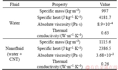
Similarly, in Ref. [52], the working fluid consists of ethylene glycol or nanofluids containing ethylene glycol used as a base fluid. The ethylene glycol properties in liquid state are widely known and correspond to the following values, for the fluid at 20 ��C and 1.0��105 Pa: ��EG,l=1076.1 kg/m3; cp,EG,l= 2343.9 J/(kg��K); ��EG,l=0.00368 kg/(m��s); kEG,l=0.26 W/(m��K) [55]. In the vapour state at 100 kPa and 471 K, ethylene glycol properties are: ��EG,v= 2.573 kg/m3; cp,EG,v=1410 J/(kg��K) [56].
An estimate of the transport properties can be performed using the Reichenberg method and the Misic and Thodos equations, applied to pure gases containing non-linear molecules, non-hydrocarbons and polar, at any temperatures [57]. From the Reichenberg method, the dynamic viscosity of saturated ethylene glycol vapour is estimated to be ��EG,v=1.304��10�C5 Pa��s, and from the equations of Misic and Thodos, cv,EG,v=79.205 kJ/(kmol��K) and kEG,v=0.0227 W/(m��K) are obtained. Finally, the enthalpy of vaporisation for the ethylene glycol at boiling point and atmospheric pressure is about 800 kJ/kg.
The nanoparticles used in Ref. [52] are aluminium oxide (Al2O3), titanium dioxide (TiO2) and zinc oxide (ZnO). The nanofluid considered herein is the ZnO. It is necessary to set three properties of the ZnO nanoparticles to use the models defined: density, specific heat and thermal conductivity. MORKO et al [58] and PASTORIZA-GALLEGO et al [38] provided such properties so that the properties used here for the ZnO nanoparticles are: ��ZnO=5607 kg/m3; cp,ZnO= 495.2 J/(kg��K); kZnO=49 W/(m��K).
Finally, to apply the representative initial and boundary conditions of the problem, the domain of both heat pipes was subdivided into five subdomains by using the CFX, so that the regions corresponding to the heat pipe wall, the wick (subdivided into three parts) and the steam chamber of these heat pipes could be defined. The configuration of these domains corresponds to follows:
1) COPPER region (heat pipe wall): solid domain, continuous, stationary; material defined as copper; heat transfer calculated by the thermal energy method (neglects compressibility effects); initial temperature defined as the temperature in steady state; cylindrical coordinates.
2) STEAM region (steam chamber): fluid domain, continuous, stationary; material defined as the working fluid in gaseous state; initial temperature defined as the temperature at the steady-state; reference pressure defined as the saturation pressure of the working fluid at the initial temperature; heat transfer calculated by the thermal energy method (neglects compressibility effects); flow defined as laminar; cylindrical coordinates.
3) WICK region: subdivided into wick contained in the adiabatic section (WICKAD), wick contained in the condenser section (WICKCOND) and WICKEVAP (wick contained in the evaporator section); fluid domain, stationary; fluid material defined as the working fluid in liquid state; thermal conductivity defined as the effective thermal conductivity calculated with Eq. (8); loss model defined as isotropic; permeability defined as a negative source term associated to the motion conservation equations (as defined in Eqs. (5) and (6)); initial temperature defined as the temperature at the steady-state; reference pressure defined as the saturation pressure of the working fluid at the initial temperature; fluid flow defined as laminar; heat transfer calculated by the thermal energy method (neglects compressibility effects); cylindrical coordinates.
However, there are some few specific boundary conditions applied to each modelled heat pipe.
For the heat pipe based on Ref. [51], the source term associated with the permeability of the heat pipe is defined as 2.283��10-9m2 and the effective thermal conductivity is calculated using a porosity value of 0.723.
For this heat pipe, the value of the mass fraction of nanoparticles along the nanofluid (2%) was provided, so that this value had to be converted to a volume fraction to apply the equations defined. Considering the given specific mass of the nanofluid components, the equivalent volume fraction of the nanofluid is 0.62%.
Similarly, for the heat pipe based on Ref. [52], the source term associated with the permeability of the heat pipe is defined as 8.558��10-11m2 and the effective thermal conductivity is calculated using a porosity value of 0.686. This heat pipe has a particular experimental behaviour that consists in obtaining a fixed temperature at the condenser end of the heat pipe for every experimental case studied. To emulate this behaviour, an additional thermal boundary condition was introduced to this region, fixing its temperature at 25 ��C. The consequences of this additional boundary condition will be discussed later on.
For both studies, all the correlations described in the analysis section for each corresponding nanofluid were applied in order to define the range of properties that the parametric analysis of the current study is going to evaluate for the liquid applied to the WICK region. These ranges can be observed in Tables 4 and 5.
Table 4 Range of properties studied for liquid working fluid inserted in heat pipe of study by LIU et al [51]
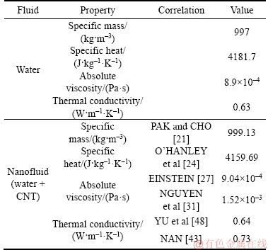
Table 5 Range of properties studied for liquid working fluid inserted in heat pipe of study by PUTRA et al [52]
Regarding the remaining boundary conditions, the heat input and output conditions, represented by Eqs. (20) to (22), must be applied to the evaporator and condenser sections to represent the main heat transfer conditions of the problem. These equations must be adapted to comprehend the change from a pure 2D model to the representative 2D model adopted herein.
The phase change occurs at the interface between the STEAM region and the WICK region. To represent the conversion of thermal energy into internal energy resulting from this phase change, heat source terms were inserted in the interface. These heat sources are analogous to the volumetric conditions represented in Eqs. (9)�C(11), in proportion to the volume of the representative model studied.
However, the application of 100% of the heat inserted in the evaporator section for boiling the working fluid neglects the existence of heat conduction on the heat pipe wall. This simplification was tested and defined as inappropriate in the heat pipes studied, once a small heat flow is always observed in the longitudinal direction of the heat pipe wall and, albeit small, it significantly influences the temperature distribution obtained at the end of the computational simulations. This behaviour is also observed in KEMPERS et al [59] and in WONG [60]; both defined the existence of a small percentage of the heat inserted in the heat pipe conducted by the heat pipe wall.
In order to correctly evaluate this percentage, an energy conservation analysis was carried out on the wall of the evaporator section of the heat pipe. This analysis introduced a proportionality parameter ��, dependent on the thermal power inserted in the heat pipe and of the heat pipe characteristics, which was multiplied by the heat source terms represented in Eqs. (9)�C(11) to account the heat loss due to heat conduction on the heat pipe wall. The present study obtained all �� parameter for each case studied, as observed in Table 6.
Similarly, for the flow representation of the motion insertion due to the phase change process, Eqs. (14) to (19) are used to insert this motion in the form of an equivalent mass flow per unit of area. This was achieved by eliminating the density term from all these equations. It was again necessary to convert these source terms from a pure 2D model to consider the representative 2D model adopted by the present study.
Table 6 Parameter �� from energy conservation analysis
Furthermore, once all these source terms are directly dependent on the actual heat used to boil the working fluid (as discussed before with the definition of the �� parameter), all these source terms must also be multiplied by the �� parameter so that there is concordance between the heat used to boil the working fluid and the consequent motion due to this boiling process.
Next, an energy conservation analysis was conducted at the heat pipe wall in the condenser section of the heat pipe modelled as in PUTRA et al [52] to evaluate the effect of the heat pipe wall temperature set at 25 ��C at the end of the condenser section of this heat pipe. An energy conservation analysis was carried out at the condenser section and the results showed that about 96.5% of the heat generated from the condensation process at the condenser section of the heat pipe is transmitted to the exterior of the heat pipe by the lateral condenser walls, while 3.5% are transmitted to the ambient because of the fixed temperature at the heat pipe condenser end; the source terms of the present model were therefore adapted to consider this change as well.
All the remaining internal boundaries of each modelled heat pipe correspond to wall-type boundaries. This means that these boundaries respect the energy conservation along them, but do not allow the flow of motion through them. The external remaining boundaries correspond to wall/adiabatic-type boundaries. The flows of energy and motion that go through them thus have zero value.
It is also important to define the solution controls for the numeric solution of the conservation equations of the problem to lead to a converged solution. For this, it is necessary to define four main configurations: Advection scheme, residual convergence control, maximum number of iterations and numeric timescale.
The selection of the advection scheme consists in the selection of a blend factor �� and a nodal gradient  for a variable �� to be applied to the solution of the advection problem posed for a variable �� such as:
 (30)
(30)
where ��ip is the value of the variable �� at the integration point; ��up is the value of the variable �� at the upwind node; and  is the vector from the upwind node to the integration point.
The computational software ANSYS CFX [61] provides three advection schemes for the solution of the CFD problem: Upwind (��=0), specified blend factor (0�ܦ¡�1) and high resolution (�� is computed through a nonlinear function at each node, such that �¡�1 without introducing new extreme).
Comparative tests showed that the most appropriate scheme for the solution of the studied problem of a heat pipe containing nanofluids consists in the second order Specified Blend Factor scheme. The use of the Upwind scheme resulted in inappropriate discretization errors, while the use of the High Resolution scheme led to discrepancies in the solution process. Also, the Specified Blend Factor scheme uses a nodal gradient equal to the average of the adjacent nodal gradients, which helps to reduce discretization errors associated with the upwind difference scheme [61].
The blend factor �� was defined as 1, reducing the advection scheme to a central difference scheme (CDS), with second order accuracy.
The residual convergence control was set using the orders of magnitude of the problem such that the maximum RMS residual is defined as 10�C7. Also, the maximum number of iterations was set as 2000, although the residual convergence control was reached in every simulation before those iterations reached their maximum. The numeric timescale was set as automatic.
4 Results and discussion
The model developed was validated using experimental data from LIU et al [51] using water as a working fluid, and the results for the heat pipe wall temperature can be observed in Figure 3. The values defined for the uncertainties associated with the experimentally measured temperatures (0.2 ��C) are not present in this picture due to the scale of the figure. However, there is qualitative good concordance between the results from the present model and the experimental data in all heat pipe sections, except the transition region between the evaporator section and the adiabatic section. Even considering that some points are out of the uncertainties range, note that the results also present good quantitative agreement with the experimental data, presenting a mean deviation from the experimental data of 0.3 ��C in the best case (10 W) and of 1.3 ��C in the worst case (80 W). This agreement is also inversely proportional to the amount of thermal power inserted into the heat pipe.
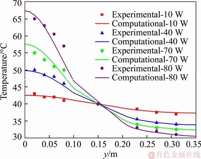
Figure 3 Temperature distributions for heat pipe containing pure water used by LIU et al [51]
The value of the thermal resistance of the heat pipe can be obtained from Eq. (31).
 (31)
(31)
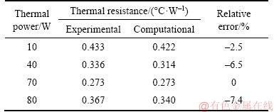
The values of the thermal resistance of this heat pipe defined for the calculated model and for the experimental study are presented in Table 7. There is a good agreement in the absolute values resulting from the computational model, once the maximum deviation from the experimental study is about 0.027 ��C/W. This represents approximately one order of magnitude below the experimental data. The behaviour of the thermal resistance is very similar in both situations, once it reaches a minimum value for an inserted thermal power of 70 W.
Table 7 Thermal resistance of heat pipe containing water used by LIU et al [51]
Similarly, water was used as a validation fluid in heat pipe [52]. The temperature distribution obtained on the heat pipe wall using water as a working fluid is presented in Figure 4.
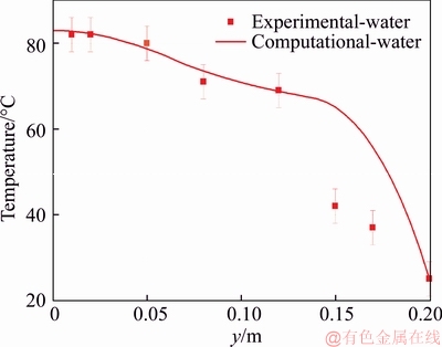
Figure 4 Temperature distribution on wall of heat pipe using water as working fluid used by PUTRA et al [52]
There is a high difference between the experimental data and the numerical solution in the condenser section. A possible explanation for such behaviour may be the type of boundary conditions applied to the condenser section. In a future study, this condition has to be improved to represent better this region.
Figure 5 exposes the evaporator and adiabatic sections temperatures on this heat pipe wall with higher detail, using water and ethylene glycol as a working fluid. In these regions, all the estimated temperature distribution remains within the error margins and the maximum deviation from the experimental values obtained corresponds to 2.1 ��C or 3.0%. The analysis in this heat pipe will be performed by evaluating only the effects in the evaporator and adiabatic sections of the heat pipe.
The value of the thermal resistance of the heat pipe is defined in Ref. [52] by Eq. (32):
 (32)
(32)
The values of the thermal resistance of this heat pipe for each working fluid are presented in Table 8. There is an overall underestimation of the thermal resistance of the heat pipe obtained by both computational models. The order of magnitude of this underestimation is approximately one order below the experimental data. The relative error was smaller using ethylene glycol.
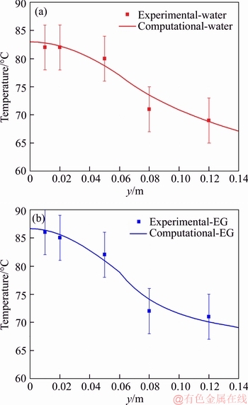
Figure 5 Temperature distribution on wall of heat pipe along evaporator and adiabatic sections using water (a) and ethylene glycol (b) as working fluid used by PUTRA et al [52]
Table 8 Thermal resistance of heat pipe containing water and ethylene glycol used by PUTRA et al [52]

The presented models were further analysed introducing custom fluids representing nanofluids. For this, it was established that the properties ranges could be represented by defining a maximum performance situation, in which the nanofluid is represented with maximum thermal conductivity and minimum absolute viscosity, and a corresponding minimum performance situation, in which the nanofluid is represented with minimum thermal conductivity and maximum absolute viscosity. These situations are going to be defined as ��DTMax�� and ��DTMin�� henceforth.
The corresponding DTMax and DTMin temperature distributions obtained computationally along the heat pipe wall for LIU e al [51] heat pipe subjected to 10, 40, 70 and 80 W are compared to the experimental results in Figure 6. This figure show that only for a thermal power of 10 W there is a significant agreement between the experimental data and the computational temperature distribution both in DTMin and DTMax situations. For this specific thermal power, the maximum temperature difference corresponds to 0.6 ��C or 1.5%. However, in this case, the small thermal power results in a small temperature difference, enhancing the precision. For the remaining thermal powers, the relative maximum deviations are 5.1% for 40 W, 4.6% for 70 W and 11.1% for 80 W.
In a wider scenario, the computational thermal behaviour of the condenser and adiabatic sections is observed to be quite close to the experimental behaviour, while in the evaporator section, the computational model significantly overestimates the gradient of temperature, obtaining higher temperatures at the evaporator end.
The most relevant physical phenomena associated with the nanofluid enhancement behaviour, such as the formation of a nanoparticle coating layer along the boiling surface, occur in the evaporator section. The present model neglects all these effects, making it safe to state that the lack of parameters accounting for these effects in the boiling process had a significant effect on the results.
The thermal resistance of each case presented can be calculated using Eq. (31). The resulting values can be observed in Table 9.
Table 9 allows inferring that the qualitative effect expected from the introduction of DTMax and DTMin situations is correctly represented, once these situations correctly defined a range of thermal resistances starting from DTMin as a lower limit and reaching DTMax as an upper limit. There is a good agreement between the thermal resistances obtained experimentally and computationally, once the values are in the same order of magnitude and with maximum deviations of 0.023��C/W for DTMin and 0.015��C/W for DTMax, or approximately one order of magnitude below the results. Note that the presence of a high-temperature gradient in the evaporator section is regarded as responsible for a better approach of the mean temperature of the evaporator, enhancing the accuracy of the results and obtaining qualitative results very close to the thermal resistance profile of LIU et al [51] heat pipe presented in Figure 1(b).
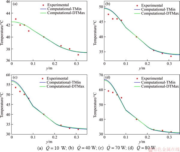
Figure 6 Temperature distributions of heat pipe wall for CNT nanofluids used by LIU et al [51]:
Table 9 Thermal resistance of heat pipe containing a CNT nanofluid used by LIU et al [51]

Similarly, the corresponding DTMax and DTMin temperature distributions obtained computationally along the heat pipe wall for the PUTRA et al [52] heat pipe containing the nanofluid composed of ethylene glycol (EG) and zinc oxide (ZnO) can be observed in comparison to the experimental results and results from pure ethylene glycol and pure water in Figure 7. The temperature distributions are observed to be even farther from the experimental results than the results from Ref. [51] heat pipe, obtaining maximum deviations of 23.9% for the DTMin situation and 20.6% for the DTMax situation.
However, the temperature distribution obtained with the nanofluids in the DTMax situation is notably positioned between the thermal distribution of the pure ethylene glycol and the thermal distribution of the pure water. This behaviour is directly related to the transport properties of these three fluids presented in Table 3 so that the results from these properties are exactly as expected and could never single-handedly reach the thermal performance observed in the experimental results.
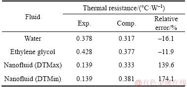
The values obtained for the thermal resistance calculated using Eq. (32) and presented in Table 10 reinforce these assumptions, once they reveal no agreement between the thermal resistance obtained experimentally and computationally. The difference for the thermal resistance of the heat pipe using nanofluid reached 0.242 ��C/W for the DTMin situation and 0.194 ��C/W for the DTMax situation, and this corresponds to the actual order of magnitude of the thermal resistances.
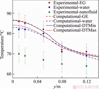
Figure 7 Temperature distributions for heat pipe heat pipe containing ethylene glycol, water and EG-ZnO nanofluid used by PUTRA et al [52]
Table 10 Thermal resistance of heat pipe containing an ethylene glycol based nanofluid used by PUTRA et al [52]
The thermal conductivity obtained experimentally for the EG-ZnO nanofluid containing different particle volume fractions from Figure 2 can be directly compared with the thermal conductivity obtained for all the analytical models studied from Figure 8. These results show an even greater discrepancy, once the model that agrees the most with the experimental results is the YU and CHOI model, in which the smaller nanofluid thermal conductivity enhancement is obtained, thus reinforcing the suggestion that the simple change of the properties of the nanofluid could never reach single-handedly the thermal performance obtained in this study.
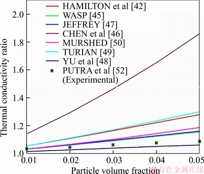
Figure 8 EG-ZnO nanofluid thermal conductivity comparison of experimental data used by PUTRA et al [52] and properties correlations
Finally, in order to observe the effect obtained using nanofluids containing a hypothetical wide range of particle volume fractions, a sensitivity analysis of this parameter was performed for both heat pipes studied to obtain temperature ranges associated with these particle volume fraction ranges. In this study, the range between 1% and 10% was defined as an appropriate range, once this range is similar to the ranges observed in the existing experimental studies and resulted in significant temperature differences when comparing DTMin and DTMax.
The problems associated with the following boundary conditions for the corresponding heat pipes were evaluated using the following nanofluid property range: LIU et al [51],  =40 W; PUTRA et al [52],=70 W.
The temperature distributions associated with heat pipe [51] for both conditions studied are presented in Figure 9.
As verified, the particle volume fraction modification corresponds to a greater impact in the condenser section, where the temperature ranges from the 40 W boundary condition to the 70 W boundary condition, while in the evaporator section, the opposite occurs. This suggests that the temperature effects in each section associated with this modification are directly related to the amount of heat inserted in the heat pipe.
From these temperature distributions, Table 11 shows that, while all the DTMax cases showed improvement in the thermal resistance of the heat pipe with the rise in the particle volume fraction, the DTMin cases showed deterioration of the thermal resistance with this rise. This occurs because the enhancement in the thermal conductivity of the nanofluid associated with the rise of the particle volume fraction was not enough to overcome the viscosity rise effects associated with the rise of the particle volume fraction of the nanofluid; therefore, the viscous effects eventually harm the thermal performance of the heat pipe. This means that some of the experimental cases reporting harmful effects obtained with heat pipes could be correctly defined with these properties correlations.
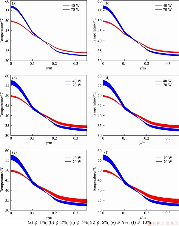
Figure 9 Sensitivity analysis of particle volume fraction in heat pipe used in Ref. [51]:
In both situations (DTMax and DTMin), there is no sign of an optimal particle volume fraction between 1% and 10%. However, a further analysis of this range could be evaluated by defining property sets (thermal conductivity and dynamic viscosity) between DTMax and DTMin.
Table 11 Thermal resistance of heat pipe containing CNT nanofluid with different particle volume fractions used in Ref. [51]
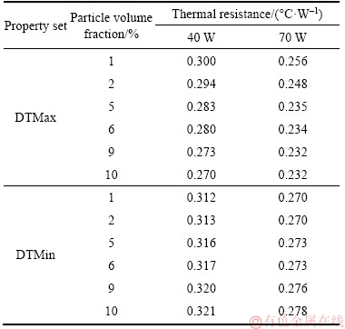
Figure 10 provides an analysis with 10 additional hypothetical situations situated linearly between DTMax and DTMin. This analysis reveals that some of these situations are curves containing a local minimum out of the ends, or in other words, containing a defined particle volume fraction in which the corresponding thermal resistance is minimal, as predicted by the literature. These situations are represented in Figure 21 as the linear approximations (LA) between 5 and 10.
Similarly, the temperature distributions associated with heat pipe evaporator [52] and adiabatic sections are presented in Figure 11.
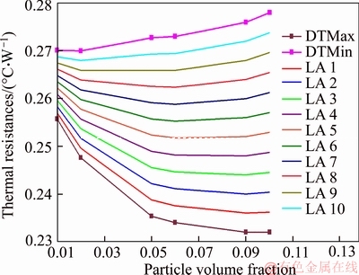
Figure 10 Thermal resistance of DTMax and DTMin situations for different particle volume fractions and = 70 W and ten additional hypothetical linear approximations
From Figure 11, heat pipe [52] is observed to behave similarly to that in Ref. [51] under 70 W, presenting a considerable range of temperatures in the evaporator section and in the 10% particle volume fraction.
Also, the thermal resistances obtained from Eq. (31) and the temperature distributions and presented in Table 12 partially agree with the behaviour obtained in Ref. [51] heat pipe, once the DTMax situation also presents a direct relation with the particle volume fraction of the nanofluid. However, it can be noticed that the DTMin situation also present a direct relation with the particle volume fraction of the nanofluid. By using this heat pipe-nanofluid combination and the properties correlations defined for these materials, no optimal particle volume fractions can thus be assumed to exist in the 1%�C10% particle volume fractions range. The differences between the physical properties of the nanofluids used in each heat pipe are assumed to play a significant role in the thermal performance of the heat pipe, providing or not a thermally optimal particle volume fraction for the nanofluid in the heat pipe.
5 Conclusions
The computational model proposed by MAHJOUB et al [11] and used by GAVTASH et al [12] for simulating the behaviour of a heat pipe can be assumed to consistently predict the thermal behaviour of a heat pipe containing a pure fluid and predicts the overall thermal behaviour of the condenser section of a heat pipe containing a nanofluid with significant accuracy. The results show agreement with the expected behaviour qualitatively and presented the maximum variations between 1.5% and 23.9% in comparison to the experimentally measured average temperatures.
However, the behaviour of the evaporator section of the heat pipe could not be correctly predicted using MAHJOUB et al [11] model as it is. This result was achieved by both the studied heat pipes so that it is possible to assume that there are effects occurring in the evaporation of the nanofluids into the heat pipe that were not taken into account by the model studied. According to literature, these effects must be directly related to the existing interactions between the nanoparticles in the nanofluids and the heating surface, which were not considered in Ref. [11] model. Also, the experimental works studied indicate direct consequences of these interactions and also pointed them out as the main causes for the heat transfer performance enhancement of the heat pipes. Hence, the introduction of new parameters in the boundary conditions of this model in order to take these effects into account is pointed out as a subject for future studies in this field of application.
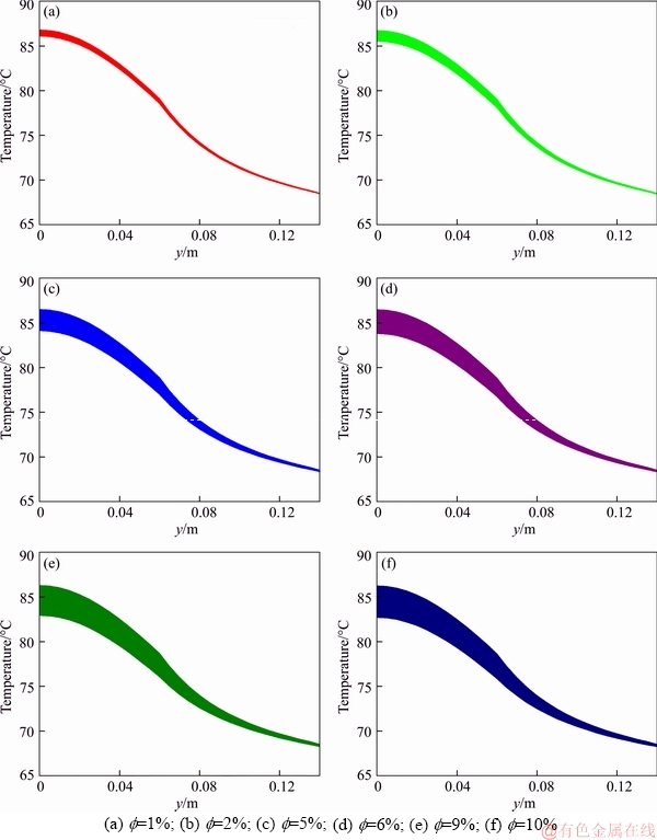
Figure 11 Sensitivity analysis of particle volume fraction in heat pipe used in Ref. [52]:
Concerning the analysis of the properties correlations of the nanofluids, the simple change in the correlations used in the simulation model is not enough to reproduce the change in the thermal performance of a heat pipe observed in the experimental studies. This affirmation is easily supported by observing the results in Ref. [52] for the thermal conductivity enhancement and the for heat pipe thermal resistance enhancement. Also, regarding these correlations, the present study succeeded in obtaining ranges of temperature distributions for the minimum and maximum performance cases, so that, once the correct behaviour of the evaporator section is reached, the current analysis could be used to validate the properties correlations.
Table 12 Thermal resistance of heat pipe containing EG-ZnO nanofluid with different particle volume fractions used by PUTRA et al [52]

From the sensitivity analysis of the thermal behaviour of the heat pipe to nanoparticles volume fraction change, it is observed as mentioned in the literature that the heat pipe can reach an optimum performance for a specific particle volume fraction, although this behaviour is limited to a very specific situation and cannot be extended to a wide range of applications. This analysis also allows observing that the properties correlations could be used to computationally represent situations in which the nanofluids deteriorate the thermal performance of the heat pipe, as shown by some experimental cases in the literature.
Finally, an additional subject for future studies is the development of a boundary condition to associate the heat conduction through the heat pipe automatically to avoid the need of the energy conservation analysis performed in this study.
Acknowledgements
The authors acknowledge CNPq (Conselho Nacional de Desenvolvimento Cient��fico e Tecnol��gico of Brazil) for the scholarship to Prof. Rodrigo Vidonscky Pinto.
References
[1] MAHMOODI M, KANDELOUSI S. Kerosene-alumina nanofluid flow and heat transfer for cooling application [J]. Journal of Central South University, 2016, 23: 983�C990.
[2] SARI M R, KEZZAR M, ADJABI, R. Heat transfer of copper/water nanofluid flow through converging-diverging channel [J]. Journal of Central South University, 2016, 23: 484�C496.
[3] SELIMEFENDIGIL F,  ZTOP H F. Mixed convection of nanofluids in a three dimensional cavity with two adiabatic inner rotating cylinders [J]. International Journal of Heat and Mass Transfer, 2018, 117: 331�C343.
[4] SIAVASHI M, BAHRAMI H R T, AMINIAN E. Optimization of heat transfer enhancement and pumping power of a heat exchanger tube using gradient and multi- layered porous foams [J]. Applied Thermal Engineering, 2018, 138: 465�C474.
[5] SELIMEFENDIGIL F, ZTOP H F. Corrugated conductive partition effects on MHD free convection of CNT-water nanofluid in a cavity [J]. International Journal of Heat and Mass Transfer, 2019, 129: 265�C277.
[6] SELIMEFENDIGIL F, ZTOP H F. Numerical analysis and ANFIS modeling for mixed convection of CNT-water nanofluid filled branching channel with an annulus and a rotating inner surface at the junction [J]. International Journal of Heat and Mass Transfer, 2018, 127: 583�C599.
[7] LIU Z H, LI Y Y. A new frontier of nanofluid research �C Application of nanofluids in heat pipes [J]. International Journal of Heat and Mass Transfer, 2012, 55(23, 24): 6786�C6797.
[8] BUSCHMANN M H. Nanofluids in thermosyphons and heat pipes: Overview of recent experiments and modelling approaches [J]. International Journal of Thermal Sciences, 2013, 72: 1�C17.
[9] SURESHKUMAR R, MOHIDEEN S T, NETHAJI N. Heat transfer characteristics of nanofluids in heat pipes: A review [J]. Renewable and Sustainable Energy Reviews, 2013, 20: 397�C410.
[10] MAHIAN O, KOLSI L, AMANI M, ESTELL P, AHMADI G, KLEINSTREUER C, MARSHALL J S, TAYLOR R A, ABU-NADA E, RASHIDI S, NIAZMAND H, WONGWISES S, HAYAT T, KASAEIAN A, POP I. Recent advances in modeling and simulation of nanofluid flows-Part II: Applications [J]. Physics Reports, 2019, 791: 1�C59.
[11] MAHJOUB S, MATABROSHAN A. Numerical simulation of a conventional heat pipe [J]. World Academy of Science, Engineering and Technology, 2008, 39: 117�C122.
[12] GAVTASH B, HUSSAIN K, LAYEGHI M, et al. Numerical simulation of the effects of nanofluid on a heat pipe thermal performance [J]. World Academy of Science, Engineering and Technology, 2012, 68: 549�C555.
[13] ZERBINI E J G J. Um estudo anal��tico-experimental de um ��heat pipe�� de temperatura moderada [D]. University of So Paulo, 1984. (in Portuguese)
[14] XUAN Y, ROETZEL W. Conceptions for heat transfer correlation of nanofluids [J]. International Journal of Heat and Mass Transfer, 2000, 43: 3701�C3707.
[15] AHMED A, NADEEM S. Biomathematical study of time-dependent flow of a Carreau nanofluid through inclined catheterized arteries with overlapping stenosis [J]. Journal of Central South University, 2017, 24: 2725�C2744.
[16] SIAVASHI M, JAMALI M. Optimal selection of annulus radius ratio to enhance heat transfer with minimum entropy generation in developing laminar forced convection of water-Al2O3 nanofluid flow [J]. Journal of Central South University, 2017, 24: 1850�C1865.
[17] SIAVASHI M, JAMALI M. Heat transfer and entropy generation analysis of turbulent flow of TiO2-water nanofluid inside annuli with different radius ratios using two-phase mixture model [J]. Applied Thermal Engineering, 2016, 100: 1149�C1160.
[18] SIAVASHI M, JOIBARY S M M. Numerical performance analysis of a counter-flow double-pipe heat exchanger with using nanofluid and both sides partly filled with porous media [J]. Journal of Thermal Analysis and Calorimetry, 2019, 135(2): 1595�C1610.
[19] BUONGIORNO J. Convective transport in nanofluids [J]. Journal of Heat Transfer, 2005, 128(3): 240�C250.
[20] MAHIAN O, KOLSI L, AMANI M, ESTELL P, AHMADI G, KLEINSTREUER C, MARSHALL J S, SIAVASHI M TAYLOR R A, NIAZMAND H, WONGWISES S, HAYAT T, KOLANJIYIL A, KASAEIAN A, POP I. Recent advances in modeling and simulation of nanofluid flows-Part I: Fundamental and theory [J]. Physics Reports, 2019, 790: 1�C48.
[21] PAK B C, CHO Y I. Hydrodynamic and heat transfer study of dispersed fluids with submicron metallic oxide particles [J]. Experimental Heat Transfer: A Journal of Thermal Energy Generation, Transport, Storage, and Conversion, 1998, 11(2): 151�C170.
[22] SHAFAHI M, BIANCO V, VAFAI K, MANCA O. An investigation of the thermal performance of cylindrical heat pipes using nanofluids [J]. International Journal of Heat and Mass Transfer, 2010, 53(1�C3): 376�C383.
[23] RASHIDI F, NEZAMABAD N, MOSAVARI. Experimental investigation of convective heat transfer coefficient of CNTs nanofluid under constant heat flux [C]// World Congress on Engineering. London: WCE, 2011.
[24] O'HANLEY H, BUONGIORNO J, MCKRELL T, HU LW. Measurement and model validation of nanofluid specific heat capacity with differential scanning calorimetry [J]. Advances in Mechanical Engineering, 2012, 4: 1�C6.
[25] MISHRA P C, MUKHERJEE S, NAYAK S K, PANDA A. A brief review on viscosity of nanofluids [J]. International Nano Letters, 2014, 4(4): 109�C120.
[26] HALELFADL S, ESTELL P, ALADAG B, DONER N, MAR T. Viscosity of carbon nanotubes water based nanofluids-Influence of concentration and temperature [J]. International Journal of Thermal Sciences, 2013, 71: 111�C117.
[27] EINSTEIN A. Eine neue bestimmung der molek��ldimensionen [J]. Annals of Physics, 906, 324(2): 289�C306.
[28] NIELSEN L E. Generalized equation for the elastic moduli of composite materials [J]. Journal of Applied Physics, 1970, 41(11): 4626�C4627.
[29] BATCHELOR G K. The effect of Brownian motion on the bulk stress in a suspensionofsphericalparticles [J]. Journal of Fluid Mechanics,1977,83(1):97�C117.
[30] BRINKMAN H C. The viscosity of concentrated suspensions and solutions [J]. The Journal of Chemical Physics, 1952, 20(4): 571�C581.
[31] NGUYEN C T, DESGRANGES F, ROY G, GALANIS N, MARE T, BOUCHER S, ANGUE MINTSA H. Temperature and particle-size dependent viscosity data for water-based nanofluids�Chysteresis phenomenon [J]. International Journal of Heat andFluidFlow, 2007, 28(6): 1492�C1506.
[32] CHOW T S. Viscosities of concentrated dispersions [J]. Physical Review E, 1993, 48(3): 1977�C1983.
[33] MARON S H, PIERCE P E. Application of Ree-Eyring generalized flow theory to suspensions of spherical particles [J]. Journal of Colloid Science, 1956, 11(1): 80�C95.
[34] BRENNER H, CONDIFF D W. Transport mechanics in systems of orientable particles. Part IV: Convective transport [J]. Journal of Colloid and Interface Science, 1974, 47(1): 199�C264.
[35] KRIEGER I M, DOUGHERTY T J. A mechanism for non-Newtonian flow in suspension of rigid spheres [J]. Transactions of theSocietyofRheology, 1959, 3(1): 137�C152.
[36] LAMAS B, ABREU B, FONSECA A, MARTINS N, OLIVEIRA M S A. Critical analysis of the thermal conductivity models for CNT based properties [J]. International JournalofThermalSciences, 2014, 78: 65�C76.
[37] SUNDAR L S, RAMANA E V, SINGH M K, SOUSA A C M. Thermal conductivity and viscosity of stabilized ethylene glycol and water mixture Al2O3 nanofluids for heat transfer applications: An experimental study [J]. International Communications in Heat andMassTransfer, 2014, 56: 86�C 95.
[38] PASTORIZA-GALLEGO M J, LUGO L, CABALEIRO D, LEGIDO J L, PI EIRO M M. Thermophysical profile of ethylene glycol-based ZnO nanofluids [J]. Applied Energy, 2014, 135: 548�C559.
[39] KWAK K, KIM C. Viscosity and thermal conductivity of copper oxide nanofluid dispersed in ethylene glycol [J]. Korea-Australia RheologyJournal, 2005, 17(2): 35�C40.
[40] LIU M S, LIN M C C, HUANG I T, WANG C C. Enhancement of thermal conductivity with carbon nanotube for nanofluids [J]. International Communications in Heat and Mass Transfer, 2005, 32(9): 1202�C1210.
[41] YU W, XIE H, CHEN L, LI Y. Investigation of thermal conductivity and viscosity of ethylene glycol based ZnO nanofluid [J]. Thermochimica Acta, 2009, 491(1, 2): 92�C96.
[42] HAMILTON R L, CROSSER O K. Thermal conductivity of heterogeneous two-component systems [J]. Industrial and Engineering Chemistry Fundamentals, 1962, 1(3): 187�C191.
[43] NAN C W, SHI Z, LIN Y. A simple model for thermal conductivity of carbon nanotube-based composites [J]. Chemical Physics Letters, 2003, 375(5, 6):666�C669.
[44] XUE Q Z. Model for thermal conductivity of carbon nanotube-based composites [J]. Physica B: Condensed Matter, 2005, 368(1�C4): 302�C307.
[45] WASP F J. Solid-liquid flow slurry pipeline transportation [M]. Berlin: TransTechPublications,1977.
[46] CHEN H S, DING Y L, HE Y R, TAN C Q. Rheological behaviour of ethylene glycol based titania nanofluids [J]. Chemical PhysicsLetters, 2007, 444(4�C6): 333�C337.
[47] JEFFREY D J. Conduction through a random suspension of spheres [J]. Proceedings of the Royal Society A: Mathematical, Physical and Engineering Science, 1973, 335(1602): 355�C367.
[48] YU W, CHOI S. The role of interfacial layers in the enhanced thermal conductivity of nanofluids: a renovated Maxwell model [J]. Journal of Nanoparticle Research, 2003, 5(1, 2): 167�C171.
[49] TURIAN R M, SUNG D J, HSU F L. Thermal conductivity of granular coals, coal-water mixtures and multi-solid quid suspensions [J]. Fuel, 1991, 70(10): 1157�C1172.
[50] MURSHED S M S, LEONG K C, YANG C. Enhanced thermal conductivity of TiO2-water based nanofluids [J]. International Journal of Thermal Sciences, 2005, 44(4): 367�C373.
[51] LIU Z H, LU L. Thermal performance of an axially microgrooved heat pipe using carbon nanotube suspensions [J]. Journal of Thermophysics and Heat Transfer, 2009, 23(1): 170�C175.
[52] PUTRA N, SEPTIADI W N, RAHMAN H, IRWANSYAH R. Thermal performance of screen mesh wick heat pipes with nanofluids [J]. Experimental Thermal and Fluid Science, 2012, 40: 10�C17.
[53] CHI S W. Heat pipe theory and practice: A sourcebook [M]. New York: Hemisphere Publishing Corporation, 1976.
[54] YANG D J, ZHANG Q, CHEN G, YOON S F, AHN J, WANG S G, ZHOU Q,WANG Q, LI J Q. Thermal conductivity of multiwalled carbon nanotubes [J]. Physical Review B, 2002, 66: 165440.
[55] The MEGlobal Group of Companies. Ethylene glycol- product guide [OL]. [2018-07-27]. http://www. meglobal.biz/media/product_guides/MEGlobal_MEG.pdf.
[56] MART NEZ I. Properties of gases [OL]. [2018-05-15]. http://webserver.dmt.upm.es/~isidoro/dat1/eGAS.pdf.
[57] GREEN D, PERRY R. Perry��s chemical engineers' handbook [M]. 8th ed McGraw-Hill Professional, 2007.
[58] MORKO H, ZGUR U. Zinc oxide: Fundamentals, materials and device technology [M]. Wiley-VCH, 2009.
[59] KEMPERS R, ROBINSON A J, EWING D, CHING C Y. Characterization of evaporator and condenser thermal resistances of a screen mesh wicked heat pipe [J]. International Journal of Heat and Mass Transfer, 2008, 51(25, 26): 6039�C6046.
[60] WONG S C. The evaporation mechanism in the wick of copper heat pipes [M]. Springer, 2014.
[61] ANSYS CFX-Solver theory guide [M]. Vol. 15.0. US: ANSYS Inc., 2013.
(Edited by YANG Hua)
���ĵ���
�����������ȹ����ܼ���ģ�͵ķ���
ժҪ������������Ӧ�����ȹ��н������轵��ʵ�飬���Եõ������ʵ������Ȼ����Ϊ�˱��������������ȹ��е���Ϊ��Ŀǰ���������ȹܺ�����������о�ģ����ȱ���������ۣ��ر��Ƕ��ڻ����������������̼���ܻ��Ҷ������о�����ˣ����о��Ƚ����ȹ�������������������̣������������ȹܵ����ݽ���ģ�⡣���������ʵ���õ�ƽ���¶���Ԥ�����ж��Ե�һ���ԣ������1.5%��23.9%֮�䡣���⣬ʵ��õ����ȹ��¶ȷֲ����ܽ�ͨ���ʵ�����������ֵ����õ�����Ҳ����������������е�Ӧ��ģ�����ӡ�ͨ����ϲ�ͬ������ģ�ͣ����Թ۲쵽���������ڴ�Ӧ���д������ŵĿ������������
�ؼ��ʣ��ȹܣ��������壻��������������������
Received date: 2018-10-25; Accepted date: 2019-04-08
Corresponding author: Fl��vio Augusto Sanzovo FIORELLI, PhD, Associate Professor; E-mail: fiorelli@usp.br; ORCID: 0000-0003- 2912-5424
Abstract: Application of nanofluids in heat pipes usually presents satisfactory experimental results regarding a thermal resistance reduction of the heat pipe. However, the existing computational studies connecting heat pipes and nanofluids lack a deeper discussion regarding the validity of the models currently used for representing the behaviour of a nanofluid in a heat pipe, particularly for unusual base fluids and nanoparticles such as carbon nanotubes or ethylene glycol. Thus, this comparative study presents the results of a set of computational simulations using pre-established equations for modelling a nanofluid in a heat pipe with experimental data from the literature. The results show agreement with the expected behaviour qualitatively and the presented maximum variations between 1.5% and 23.9% in comparison to the experimentally measured average temperatures. Also, the experimentally obtained temperature distribution of a heat pipe could not be reached numerically only with the use of adequate thermal properties, indicating that the boiling phenomenon is more complex than the current model used for computational simulations. Moreover, the existence of an optimal particle volume fraction for using nanofluids in this application could be observed by combining different properties models.
