

Effect of adding carbon nanotubes on stress of Fe3Al intermetallics
PANG Lai-xue(����ѧ)1, ZHANG Jin-sheng(�Ž���)1, XU Jing(�� ��)1, SUN Kang-ning(���)2
1. Department of Civil Engineering, Shandong Jiaotong University, Ji��nan 250023, China;
2. School of Materials Science and Engineering, Shandong University, Ji��nan 250061, China
Received 7 July 2008; accepted 29 October 2008
Abstract:
Analyses on the stress in the carbon nanotube/Fe3Al composites were performed. The biphase interface valence electron structure was established on the basis of Pauling��s nature of the chemical bond. The stress occurs by the huge interface electron density difference, which will block the Fe3Al grain agglomeration and growth. With the X-ray diffractions, the calculated magnitude of compressive stress existing in the CNT/Fe3Al interface is 0.38 GPa. The experimental result verifies that the stress has a positive effect on the enhancement of mechanical properties of composite.
Key words:
interface stress; CNT/Fe3Al composite; interface valence electron structure;
1 Introduction
Iron aluminide (Fe3Al) is a very important structural material, and has been applied in varied fields such as power plant, tribological and electrical components[1-3]. Recently, a few studies have been carried out to utilize carbides or borides as reinforcements in iron aluminides via a powder metallurgy process[4-5]. Ceramic particles can be utilized as reinforcement to improve the high-temperature strength of intermetallic alloys[6-7].
Carbon nanotubes(CNTs) are new allotropic carbon materials with excellent mechanical, electrical, thermal properties, and chemical stability. It is widely perceived that CNTs will allow the construction of composites with extraordinary mechanical properties. Incorporation of these one-dimensional nanostructured materials into ceramics[8-9], metal[10-11], polymer[12-13] has attracted interest of researchers in recent years. However, less study concerned the fabrication and properties of CNT-reinforced intermetallic matrix composites until our group recently suggested an spark plasma sintering method for the synthesis of CNT/Fe3Al nanocomposites with improved mechanical properties[14]. Herein, we introduce the effect of adding CNT into Fe3Al on the microstructure and stress of composites as well as their mechanical properties. Biphase interface valence electron structure was used to analyze the stress essence.
2 Experimental
2.1 Interface electron structure calculation
In order to understand the stress distribution on the CNT/Fe3Al interface, we carried out the interface electron structure calculation based on the Pauling��s nature of chemical bond. The interface electron structure method has been described elsewhere[15-16].
2.2 Composite synthesis
The multi-walled carbon nanotubes(MWNTs) used here have diameters ranging from 10 to 30 nm, and length ranging from 500 nm to 500 ��m. Fe3Al powder was fabricated by mechanical alloying[17]. The CNT/Fe3Al intermetallics matrix composite was sintered using spark plasma sintering(SPS) apparatus (Dr. Sinter 2080, Sumitomo Coal Mining Co., Tokyo, Japan). The composite powders with 5% (volume fraction) CNTs were prepared to fabricate intermetallics matrix composites. In addition, the specimen without nanotubes was also fabricated for comparison. The synthesis process of CNT/Fe3Al powders has been reported in our previous work[18]. The fracture toughness was tested by three-point method with a chevron notch on SANS universal testing machine.
3 Results and discussion
3.1 Relative electron density difference across interface
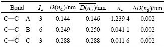
The carbon nanotubes can be visualized as a sheet of graphite that has been rolled into a tube and multi-walled nanotubes are simply composed of concentric single-walled nanotubes. Whether single-walled carbon nanotubes or multi-walled carbon nanotubes, hexagonal ring is the basic unit, so hexagonal ring is regarded as structural unit of CNT, as shown in Fig.1. The experimental covalent bonding distance ![]() and the identity bond number I�� in hexagonal carbon ring are listed in Table 1.
and the identity bond number I�� in hexagonal carbon ring are listed in Table 1. ![]() is the experimental covalent bond distance for an individual atom, which can be determined by solid geometry. The identity bond number I�� can be calculated using the formula in Ref.[19].
is the experimental covalent bond distance for an individual atom, which can be determined by solid geometry. The identity bond number I�� can be calculated using the formula in Ref.[19].
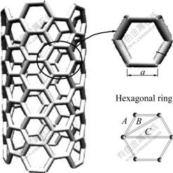
Fig.1 Hexagonal rings of carbon nanotube
Table 1 Valence electron structure parameters of carbon nanotube
Based on the Pauling��s nature of the chemical bond [20] for a crystal composed of different elements, theoretical bond length Du-v(n��) between atom u and v is represented as
Du-v(n��)=Ru(1)+Rv(1)-��log(n��) (1)
where Ru(1) and Rv(1) are single bond radii of atom u and v, respectively; n�� is pair number of bond covalent electron; ��=0.071 nm, is the empirical constant for carbon. So, the theoretical bond length can be represented as
DC��C(nA)=RC(1)+RC(1)-��lg(nA) (2a)
DC��C(nB)=RC(1)+RC(1)-��lg(nB) (2b)
DC��C(nC)=RC(1)+RC(1)-��lg(nC) (2c)
Eq.(1) substracts Eqs.(2a)-(2c), respectively, and we can get
lg ��A=[DC��C(nA)-DC��C(nA)]/�� (3a)
lg ��B=[DC��C(nA)-DC��C(nB)]/�� (3b)
lg ��C=[DC��C(nA)-DC��C(nC)]/�� (3c)
where ����=n��/nA (��=B, C) is the ratio of pair number of covalent electron distributed on �� bond to that distributed on A bond.
For a carbon ring, the total covalent electron number is
![]() (4)
(4)
where ![]() is covalent electron number contributed by carbon atom. On the other hand, these covalent electrons are distributed on the every covalent bond, so that
is covalent electron number contributed by carbon atom. On the other hand, these covalent electrons are distributed on the every covalent bond, so that
![]() (5)
(5)
![]() (6)
(6)
![]() (7)
(7)
Inserting the value of n��, which is calculated by inserting the covalent electron number nc, experimental bond lengths D(n��) and equivalent bond number I�� (��=A, B, C) into Eqs.(3a)-(3c), into Eqs.(4)-(7), we can get the values of empirical theoretical bond lengths, ![]() , and the bond length differences(BLD), ?D(n��), between experimental bond lengths D(n��) and theoretical bond lengths
, and the bond length differences(BLD), ?D(n��), between experimental bond lengths D(n��) and theoretical bond lengths ![]() . The calculated minimal bond length differences are also listed in Table 1.
. The calculated minimal bond length differences are also listed in Table 1.
The DO3 cell structure of Fe3Al is shown in Fig.2, ![]() (m3m) type of space group. One DO3 cell consists of four A2 (bcc) cells and four B2 cells, belonging to face centered cubic structure. Its lattice constant a is 0.578 nm. The Fe atoms located in the center of cell interior, in the center of cell edge and the top of the cell are expressed as Fe��; the Fe and Al atoms at the diagonal 1/4 and 3/4 of the cell interior are expressed as Fe�� and Al, respetively. Therefore, the structure formula of Fe3Al can be written as Fe��Fe2��Al.
(m3m) type of space group. One DO3 cell consists of four A2 (bcc) cells and four B2 cells, belonging to face centered cubic structure. Its lattice constant a is 0.578 nm. The Fe atoms located in the center of cell interior, in the center of cell edge and the top of the cell are expressed as Fe��; the Fe and Al atoms at the diagonal 1/4 and 3/4 of the cell interior are expressed as Fe�� and Al, respetively. Therefore, the structure formula of Fe3Al can be written as Fe��Fe2��Al.
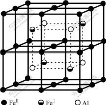
Fig.2 Unit cell of DO3 structure of Fe3Al
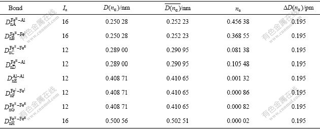
While performing calculation for Fe3Al, ��=0.060 nm is substituted for that of carbon, and we can get the values of empirical theoretical bond lengths ![]() and the bond length differences(BLD) ?D(n��) between experimental bond lengths D(n��) and experimental theoretical bond lengths
and the bond length differences(BLD) ?D(n��) between experimental bond lengths D(n��) and experimental theoretical bond lengths ![]() by taking a similar calculation as above. The calculated minimal BLD results are listed in Table 2[21].
by taking a similar calculation as above. The calculated minimal BLD results are listed in Table 2[21].
Table 2 Valence electron structure parameters of Fe3Al
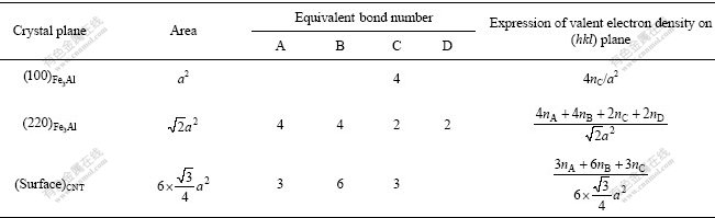
If the orientation of a covalent bond in a structure unit is determined by the line of two bonding atoms, the covalent electron number on a crystal plane should be that of all bonds on the plane. So, average covalent electron density on the (hkl) plane is defined as
![]() (8)
(8)
where S(hkl) is the area of the reference unit of the considered (hkl) plane, and ![]() is covalent electron number on the area of the reference unit.
is covalent electron number on the area of the reference unit.
![]() (��=A, B, ��) (9)
(��=A, B, ��) (9)
where ![]() is the equivalent bond numbers of �� bond distributed on (hkl) plane, and can be calculated by
is the equivalent bond numbers of �� bond distributed on (hkl) plane, and can be calculated by
![]() =IMISIK (10)
=IMISIK (10)
where IM is the reference atom number in the reference area unit; IS is the number of congenetic atoms with the reference atom at the same distance to it on (hkl) plane; IK is a parameter, whose value is one when the atoms to form the bond are of the same kind, or two when they are of different kinds. According to crystal symmetry and using Eq.(10), we have made a calculation of the equivalent bond numbers ![]() of �� bond distributed on various (hkl) planes.
of �� bond distributed on various (hkl) planes.
Based on the expression of valent electron density on various plane as listed in Table 3, we can get ��CNT=68.019 3-74.240 3 nm-2, ![]() 0.783 8- 1.814 8 nm-2,
0.783 8- 1.814 8 nm-2, ![]() 6.475 8-8.969 8 nm-2.
6.475 8-8.969 8 nm-2.
Table 3 Electron density of low-index crystal planes for Fe3Al and CNT
The relative electron density difference (REDD) across the CNT/Fe3Al composite interfaces is defined as
 (11)
(11)
From the minimization of the electron density differences across interface that is continuity principle of electric charge in quantum mechanics, the interface electron density is defined as continuity in first-class approximately, namely, ?�ѣ�10% is regarded as continuity. These definitions are significant in material fields[22].
From the results of CNT/Fe3Al, it can be found that the REDD deviates from continuity under the condition of the first order approximation. The larger the ?�� is, the greater the change of the atom size on interfaces is, and the larger the stress is, the higher the interface energy will be. The great driving force of increasing the interface area will be needed, so the growth of the second phase particle will be more difficult. Meanwhile, the larger ?�� also indicates that the changes of atom state on interface are stronger than those within phase. When the interface moves, the atom state on interface will need more adjustment, which will make the increase of the interface area more difficult. So, the large ?�� will block the grain agglomeration and growth, then Fe3Al will become fine and dispersive at high temperature, as illustrated in Fig.3.
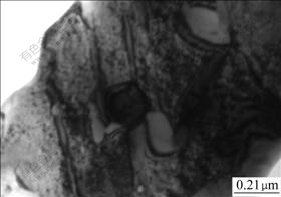
Fig.3 TEM image of CNT interlocking grains of Fe3Al
3.2 Stress calculation and effect on mechanical property
ZHOU et al[23] studied the compressibility of multi-walled carbon nanotubes(MWNT) through an in situ high-pressure X-ray diffraction technique, and obtained a radial compressibility (��lna/��P, a is C��C bond length) of 3.1��10-2 GPa-1 in pressure range from 0.1 to 1 GPa. This pressure-induced deformation can also be reflected by the change of interlayer spacing d(002) according to the following equation:
![]() (12)
(12)
In the XRD spectrum of composite with 5% (volume fraction) CNTS (Fig.4), we have observed the shift of d(002) peak from 25.96? to 26.28?. Thus, the calculated compressive pressure on the CNTs can be determined to be 0.38 GPa.
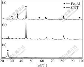
Fig.4 XRD patterns of pure Fe3Al (a), CNTs/Fe3Al composites (b) and pure CNTs (c)
The high compressive stress at CNT/Fe3Al interface is expected to block the crack propagation, ultimately enhancing the toughness. Our measurement positively observed this enhancement in Fig.5. A toughness value of 38 MPa��m1/2 is obtained, which increases by 52% compared with the toughness of 25 MPa?m1/2 for the carbon-free Fe3Al intermetallics. This toughness enhancement shows the important effect of high interface strength on the mechanical properties of a composite, and shed light on the other toughened carbon nanotubes/ceramic composite by using multi-walled carbon nanotubes instead of single-walled carbon nanotubes, which is expected to scale up in industry owing to its reasonable price and facile synthesis of MWNTs. Additionally, the crack bridging effect of carbon nanotubes also has a positive role to improve material toughness. The carbon nanotubes, bridging the two crack surfaces as shown in Fig.6, strongly supports the crack bridging effect during the crack propagation. Some wrapped CNT aligns perpendicular to the crack direction and bridges a matrix crack, meaning that they carry tensile load.
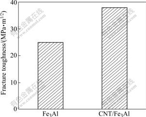
Fig.5 Fracture toughness of Fe3Al and CNT/Fe3Al composites
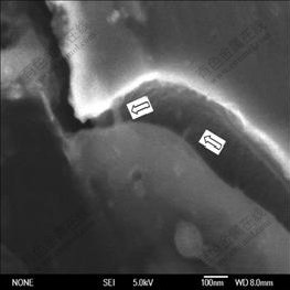
Fig.6 SEM micrograph of Fe3Al/CNT composites (Surface crack bridged by nanotubes)
4 Conclusions
In this communication, we report on stress analysis in the Fe3Al/CNT composites. High compressive stress in the Fe3Al/CNT interface is predicted with the interface electron density. The stress is estimated and calculated through XRD spectra. Moreover, this high stress positively enhanced the toughness of composites.
Appendix
�� value can be selected as
��= 0.71 ? when ![]() ��0.250 ? or
��0.250 ? or ![]() ��0.750 ?
��0.750 ?
��=0.600 ? when 0.300 ?��![]() ��0.700 ?
��0.700 ?
��=0.710-2.2 ? when ![]() =0.25+�� or
=0.25+�� or
![]() =0.750-�� (0���ţ�0.05)
=0.750-�� (0���ţ�0.05)
where ![]() indicates the largest n�� among nA, nB, ��, nN.
indicates the largest n�� among nA, nB, ��, nN.
References
[1] DEEVI S C, SIKKA V K, LIU C T. Processing, properties, and applications of nickel and iron aluminides [J]. Prog Mater Sci, 1997, 42: 177-192.
[2] LIU C T, MAZIASZ E P, SCHNEIBEL J H. Recent advances in B2 iron aluminide alloys: Deformation, fracture and alloy design [J]. Mater Sci Eng A, 1998, 258: 84-98.
[3] FROES F H, SURYANARAYAN C, ELIEZER D. Review synthesis properties and applications of titanium aluminides [J]. J Mater Sci, 1992, 27: 5113-5140.
[4] SURYANARAYAN R, SCHNEIBEL J H. Processing iron aluminide composites containing carbides or borides [J]. JOM, 1997, 49: 50-53.
[5] SCHNEIBEL J H, CAMICHAEL C A, SPECHT E D, SUBRAMANIAN R. Liquid-phase sintered iron aluminide-ceramic composites [J]. Intermetallics, 1997, 5: 61-67.
[6] PENG L M, LI H, WANG J H, GONG M. High strength and high fracture toughness ceramic-iron aluminide (Fe3Al) composites [J]. Mater Lett, 2006, 60: 883-887.
[7] PARK B G, KO S H, PARK Y H, LEE J H. Mechanical properties of in situ Fe3Al matrix composites fabricated by MA�CPDS process [J]. Intermetallics, 2006, 14: 660-665.
[8] ZHAN G D, KUNTZ J D, WAN J L, MUKERJEE A K. Single-wall carbon nanotubes as attractive toughening agents in alumina-based nanocomposites [J]. Nat Mater, 2003, 2: 38-42.
[9] MA R Z, WU J, WEI B Q. Processing and properties of carbon nanotubes�Cnano-SiC ceramic [J]. J Mater Sci, 1998, 33(21): 5243- 5246.
[10] GEORGE R, KASHYAP K T, RAHUL R, YAMDAGNI S. Strengthening in carbon nanotube/aluminium (CNT/Al) composites [J]. Scripta Mater, 2005, 53(10): 1159-1163.
[11] SEUNG I C, KYUNG T K, SALMAN N A. Extraordinary strengthening effect of carbon nanotubes in metal-matrix nanocomposites processed by molecular-level mixing [J]. Adv Mater, 2005, 17: 1377-1381.
[12] MAMEDO A A, KOTOV N A, PRATO M, GULDI D M, WICKSTED J P, HIRSCH A. Molecular design of strong single-wall carbon nanotube/polyelectrolyte multilayer composites [J]. Nat Mater, 2002, 1: 190-196.
[13] PULICKEL M A, LINDA S S, CINDY G, ANGEL R. Single-walled carbon nanotube-polymer composites: Strength and weakness [J]. Adv Mater, 2000, 12(10): 750-753.
[14] PANG L X, SUN K N, REN S, SUN C, BI J Q. Microstructure, hardness, and bending strength of carbon nanotube�Ciron aluminide composites [J]. J Composite Mater, 2007, 41(16): 2025-2031.
[15] GUO Yong-quan, Y? Rui-huang, ZHANG Rui-lin, ZHANG Xin-hui, TAO Kun. Calculation of magnetic properties and analysis of valence electronic structures of LaT13-xAlx (T=Fe, Co) compounds [J]. J Phys Chem B, 1998, 102: 9-16.
[16] ZHANG Xiao-jun, ZHANG Jian-min, XU Ke-wei. Valence electron structure analysis of epitaxial growth of diamond (100) film on Si and c-BN substrate [J]. J Cryst Growth, 2006, 290: 229-234.
[17] FAN R H, SUN J T, GONG H Y, SUN K N,WANG W M. Structural evolution of mechanically alloyed nanocrystalline Fe-28Al powders [J]. Powder Technol, 2005, 149: 121-126.
[18] PANG Lai-xue, SUN Kang-ning, REN Shuai, SUN Chang, FAN Run-hua, LU Zhi-hua. Fabrication and microstructure of Fe3Al matrix composite reinforced by carbon nanotube [J]. Mater Sci Eng A, 2007, 447: 146-149.
[19] ZHANG R L. Empirical electron theory of solid and molecules [M]. Changchun: Jilin Science and Technology Publishing House, 1993. (in Chinese)
[20] PAULING L. The nature of the chemical bond [M]. Ithaca, NY: Cornell University Press, 1960.
[21] PANG Lai-xue, SUN Kang-ning, SUN Jia-tao, FAN Run-hua, REN Shuai. Interface electron structure of Fe3Al/TiC composites [J]. Trans Nonferrous Met Soc China, 2006, 16(2): 294-298.
[22] LIU Yan, LIU Zhi-lin, ZHANG Cheng-wei. Calculation and analysis of valence electron structure of Mo2C and V4C3 in hot working die steel [J]. Journal of Iron and Steel Research International, 2006, 13(1): 50-56.
[23] ZHOU O, FLEMING R M, MURPHY D W, CHEN C H, HADDON R C, RAMIREZ A P, GLARUM S H. Defects in carbon nanotubes [J]. Science, 1994, 263: 1744-1747.
Foundation item: Project(Z200816) supported by Research Initial Foundation for Doctor of Shandong Jiaotong University, China
Corresponding author: PANG Lai-xue; Tel: +86-531-80683155; E-mail: lxpang@sdjtu.edu.cn
DOI: 10.1016/S1003-6326(08)60429-X
