

J. Cent. South Univ. (2018) 25: 1717-1731
DOI: https://doi.org/10.1007/s11771-018-3863-z

Mesh stiffness calculation of cycloid-pin gear pair with tooth profile modification and eccentricity error
LI Xuan(����)1, 2, CHEN Bing-kui(�±���)2, WANG Ya-wen(������)3, LIM Teik Chin3
1. School of Mechanical and Electric Engineering, Soochow University, Suzhou 215021, China;
2. State Key Laboratory of Mechanical Transmission, Chongqing University, Chongqing 400030, China;
3. Department of Mechanical and Aerospace Engineering, University of Texas at Arlington,Arlington, TX, 76019, USA
 Central South University Press and Springer-Verlag GmbH Germany, part of Springer Nature 2018
Abstract:
Cycloid speed reducers are widely used in many industrial areas due to the advantages of compact size, high reduction ratio and high stiffness. However, currently, there are not many analytical models for the mesh stiffness calculation, which is a crucial parameter for the high-fidelity gear dynamic model. This is partially due to the difficulty of backlash determination and the complexity of multi-tooth contact deformation during the meshing process. In this paper, a new method to calculate the mesh stiffness is proposed including the effects of tooth profile modification and eccentricity error. The time-varying mesh parameters and load distribution of cycloid-pin gear pair are determined based on the unloaded tooth contact analysis (TCA) and the nonlinear Hertzian contact theory, allowing accurate calculations of the contact stiffness of single tooth pair and the torsional stiffness of multi-tooth pairs. A detailed parametric study is presented to demonstrate the influences of tooth profile modification, applied torque and eccentricity error on the torsional mesh stiffness, loaded transmission error, Hertzian contact stiffness and load sharing factor. This model can be applied to further study the lost motion and dynamic characteristics of cycloid speed reducer and assist the optimization of its precision, vibration and noise levels.
Key words:
cycloid speed reducer; mesh stiffness; tooth contact analysis; load distribution; modification��
Cite this article as:
LI Xuan, CHEN Bing-kui, WANG Ya-wen, LIM Teik Chin. Mesh stiffness calculation of cycloid-pin gear pair with tooth profile modification and eccentricity error [J]. Journal of Central South University, 2018, 25(7): 1717�C1731.
DOI:https://dx.doi.org/https://doi.org/10.1007/s11771-018-3863-z1 Introduction
Cycloid speed reducers are becoming prominent for precision transmission due to the advantages of small backlash, compact size, large reduction ratio, high torsional rigidity and high load capacity [1, 2]. A two-stage speed reducer (see Figure 1), known as the 2KV type cycloid speed reducer, is widely used as the industrial robot joints where precision output motion and repeatability are vital [3]. Its first reduction is the involute planetary gear drive with the cycloid-pin gear drive as the second reduction. Despite the increasing popularity, currently there are no available design standards for cycloid speed reducer [4].

Figure 1 Typical structure of two-stage 2KV type cycloid speed reducer
Gearbox noise and vibration are considered to be one of the major engineering problems nowadays, which are usually caused by external excitations such as fluctuation of applied torque and operating speed, and internal excitations such as time-varying mesh stiffness and transmission errors [5]. However, for the cycloid speed reducer, review of literature reveals that many research works focus on its geometrical design [6�C8], kinematic and force analyses [9�C12] and lubrication [13�C15], very few studies in the open literature are found to address the dynamic characteristics of cycloid speed reducer. In order to comprehensively understand the vibration properties, it is necessary to evaluate the mesh stiffness and transmission error of the cycloid-pin gear pair effectively. There has been ongoing research performed using the finite element method (FEM). XU et al [16] proposed a multi-body dynamic model of the KHV type cycloid speed reducer for analyzing the contact dynamics considering the turning-arm cylindrical roller bearing effects. HSIEH [17] investigated the dynamic contact and collision conditions of the transmission components in cycloid drives with pinwheel and non-pinwheel components. KIM et al [18] performed contact force and torsional rigidity analyses of a cycloid speed reducer considering finite bearing stiffness as well as nonlinear Hertzian contact stiffness based on the FEM and Hertzian contact theory. KUMAR et al [4] presented a new method for the effective determination of the elastic torsional compliance of a single-stage cycloid drive based on static experimental results. TRAN et al [3] investigated the lost motion of a cycloid reducer combining finite element and kinematic analyses. The finite element method can automatically consider the effect of the tooth deviations. However, the finite element models are computationally expensive, especially with refined element mesh.
On the other hand, analytical methods, as alternative tools, have shown good agreements with the finite element models but require much less computation time for the involute gearing [5]. However, for the cycloid drive, there is no accurate analytical model for calculating the mesh stiffness and transmission errors. This is partially due to the difficulty of backlash determination and the complexity of multi-tooth contact deformations. Some researchers calculated the stiffness based on the oversimplified and inaccurately assumed analytical model or considered the gear pair with ideal tooth profile [19, 20]. In practice, the tooth profile usually deviates from the theoretical position, which is usually generated by unintentional manufacturing and assembly errors as well as the intentional tooth profile modifications [21]. Unlike the tooth profile modification of involute gearing for vibration and noise reduction, the tooth profile modification of cycloid gear is to accommodate the interferences caused by tooth deformations, manufacturing errors and thermal influence, to provide better lubrication conditions, and to accomplish easier assembling and disassembling [7, 22]. The cycloid gear tooth profile is usually modified to guarantee a reasonable mesh clearance between tooth pairs [23]. As a result, the theoretical tooth contact becomes more complicated, and the number of tooth pairs in simultaneous contact will decrease. Gear tooth deviations caused by the tooth profile modification and assembly error are considered to have significant effects on the mesh stiffness of cycloid gear pair, which will further cause the noise, vibration and lost motion of cycloid speed reducers. However, the current analytical models cannot include these effects.
Therefore, the main objective of this paper is to develop a generic analytical mesh stiffness model and to study the influence of the tooth profile modification and eccentricity error on the mesh stiffness, loaded transmission error and load sharing factor. These parameters are the basis for the gear static and dynamic analyses and provide a convenient way for the investigation on gear vibration and noise reduction.
The rest of this paper is structured as follows: Section 2 introduces the cycloid gear tooth profile modification methods and gives the equations of tooth profile and its curvature radius. Section 3 presents a new analytical mesh stiffness model of cycloid-pin gear pair considering the tooth profile modification and eccentricity error. The torsional stiffness of the multi-tooth pairs is estimated considering the number of tooth pairs in contact and total elastic angular rotation of the cycloid gear. With this, loaded transmission error and load sharing factor can be calculated. Then, based on the proposed model, the parametric studies on the effects of the tooth profile modification, applied torque levels and eccentricity error is investigated with an example cycloid-pin gear pair in Section 4, Finally, a conclusion discussion is given in Section 5.
2 Tooth profile modification
As shown in Figure 2, there are three coordinate systems being defined for tooth profile modification (TPM) use. Two movable coordinate systems S1(x1, y1), S2(x2, y2) and a fixed coordinate system Sf (xf, yf) are rigidly connected to the pin, the cycloid gear and the frame respectively. The eccentricity e is the distance between o1 and o2. The radius of pin position a is the distance between the center of a pin and o1. The radius of pins is ��. The angular parameter at contact point M is ��. The rotation angles f2 and f1 have the relationship f2/f1=n1/n2. The numbers of pins and cycloid gear teeth are n1 and n2. The modified tooth profiles of the cycloid gear can be obtained by modifying two tooth profile parameters �� and �� in individual and combined conditions [23]. The general equation of the modified tooth profiles and corresponding angular parameters for single tooth can be represented as follows:
 (1)
(1)
 (2)
(2)
where  and ���� and ���� are the modification amounts of pin position and pin radius, respectively. Based on the theory of gearing [24, 25], the curvature radius of the whole modified cycloid tooth profile ��c can be represented as:

 (3)
(3)
where is the angular parameter of cycloid gear tooth profile.

Figure 2 Coordinate system for modified cycloid gear tooth profile
3 Analytical mesh stiffness model
The overall methodology used to develop the analytical mesh stiffness model of cycloid drives can be summarized in Figure 3 by the following steps:
Step 1: Inputting design parameters describe the standard or modified tooth profile of the cycloid gear.
Step 2: Preforming the unloaded tooth contact analysis (TCA). By transferring the tooth profiles into the global coordinate system, the mesh information can be obtained by satisfying the contact conditions.
Step 3: Conducting the load distribution analysis. A set of compatibility and equilibrium conditions are defined and solved simultaneously by an iterative numerical algorithm. The Hertzian contact stiffness that depends on the load and contact geometry is considered to establish the relationship between the load and deformation.
Then, the contact stiffness of single tooth pair, the torsional stiffness of multi-tooth pair, load sharing factor and loaded transmission error can be calculated. Following sections describe the key features of these main steps shown in Figure 3.
3.1 Unloaded tooth contact analysis
The unloaded tooth contact analysis (TCA) has been successfully applied for a cycloidal pump [26]. It can provide time-varying mesh parameters such as contact points, backlash angle and unloaded transmission error. In this study, it is first applied as a preprocessor for the load distribution analysis of cycloid drives with the tooth profile modification and eccentricity error.
A pair of cycloid gear and pins is shown in Figure 4, where S1(x1, y1) and S2(x2, y2) are rigidly connected with pins and the cycloid gear, and the fixed coordinate system Sf (xf, yf) coinciding with S1 is fixed to the frame. Therefore, the position vector  and normal vector
  of all the pin profiles can be represented directly in Sf:
 (4)
(4)
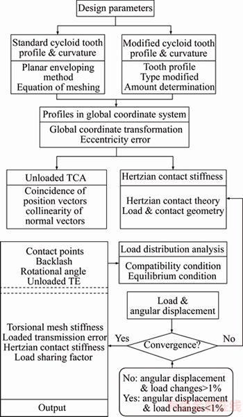
Figure 3 Flowchart of analytical mesh stiffness model

Figure 4 Coordinate systems for unloaded TCA model
 (5)
(5)
where i stands for the pin number; ��r is the angle between two adjacent pins; k is the unit vector in the z direction and ��ri is the angular parameter of pin profile at the contact point.
The position vector  and its normal vector
  can be rewritten in S2:
 (6)
(6)
 (7)
(7)
where ��ci is the angular parameter of contact point on the cycloid tooth profile. Then, the position vector  and its unit normal vector
  can be represented in Sf by the following coordinate transformation:
 (8)
(8)
 (9)
(9)
where fci is the rotational angle corresponding to the cycloid gear tooth, and the coordinate transformation matrix is represented as follows:
 (10)
(10)
 (11)
(11)
where ��e is the eccentricity error, which refers to the center distance error during the assembly or manufacturing process. It can be a positive or negative value wherein the center distance of the cycloid gear and the ring gear is increased or decreased respectively. Note that the absolute value of ��e must be controlled to be less than the radial clearance between tooth pairs to avoid the interference.
Two contact conditions should be satisfied for performing the unloaded TCA. The first condition is the coincidence of position vectors of modified cycloid gear tooth and pin profiles at contact points in two-dimensional plane. The second condition is the collinearity of normal vectors of both profiles at contact points. These equations can be represented as follows:
 (12)
(12)
 (13)
(13)
The above equations yield a system of three independent nonlinear equations in four unknowns ��ri, ��ci, fci and fin, since the normal vectors  . For a given input crankshaft angle fin, the remaining three unknowns can be solved.
The backlash fbli between the cycloid gear tooth and its mating pin is defined as the angular difference between the rotational angle fc of cycloid gear disc and calculated rotational angle fci of corresponding cycloid gear tooth:
 (14)
(14)
where  is the maximum value of fci. This definition can be used for the following load distribution analysis as it directly describes the relation between number of contacting tooth pairs and relative motion of the cycloid gear disc. The backlash is one of main causes to the lost motion of speed reducers, which will lead to position uncertainty in a motion system.
3.2 Load distribution analysis
Conditions of compatibility and equilibrium must be satisfied simultaneously during the meshing process. As shown in Figure 5, the number of tooth pairs in contact can be determined by the following compatibility condition:
 (15)
(15)
where ��fc is the elastic angular rotation of cycloid gear, and ��i is a small angular displacement of the corresponding cycloid gear tooth.
Considering each contact point as a small spring associated with a Hertzian contact stiffness Kn along the line of action, the mechanics model used for load distribution analysis is shown in Figure 6. The number of springs is equal to that of contacting tooth pairs. Therefore, the load and moment static equilibrium equations assure that the torque caused by loads acting on tooth pairs must be equal to the external torque applied on the cycloid gear:
 (16)
(16)
Fci=Kni��ci (17)
where Fci is the load distributed on the corresponding cycloid gear tooth, ��ci=��ili is the elastic deformation along the line of action, as shown in Figure 6. The arm of force li is equal to the distance from the rotational center o2 of cycloid gear to the line of action:

 (18)
(18)
Once the instantaneous contact points are determined at a given input crankshaft angle fin by the unloaded TCA, the unknowns ��c, li and fbli can be calculated. Then, an iterative technique is used to obtain the solutions, as shown in Figure 3. The iterative procedure is continued until the changes of the load and angular displacement will successfully converge within 1%.

Figure 5 Deformation compatibility model

Figure 6 Load and moment equilibrium mechanics model
3.3 Hertzian contact stiffness
As mentioned above, the last step before the load distribution analysis can be performed is determining the contact stiffness of tooth pairs to establish the relationship between the load and deformation. Based on the Hertzian contact theory [27], a pair of cycloid tooth and pin contact can be approximated by the contact of two parallel cylinders with equivalent radius of curvature at the contact point. The elastic deformation is very small compared to the size of tooth pairs such that the radii of curvatures over the contact zone remain unchanged. Therefore, the Hertzian contact stiffness Kn can be represented as:
 (19)
(19)
 (20)
(20)
 (21)
(21)
 (22)
(22)
where b is the contact width, E* is the equivalent elasticity modulus and ��* is the equivalent radius of curvature. Symbol B is the width of cycloid gear, E and v are the elasticity modulus and Poisson��s ratio. Subscripts r and c refer to the pin and cycloid gear, respectively. The stiffness Kn is a nonlinear function of the load, material property and contact geometry.
3.4 Torsional mesh stiffness
The torsional mesh stiffness (TMS) of cycloid gear pair is defined as the ratio between the applied torque and the total elastic angular rotation of the cycloid gear due to the tooth contact deformation, which can be represented as:
 (23)
(23)
This definition directly describes the relation between applied torque and relative motion of the cycloid gear, which can be used for the torsional dynamic model of cycloid speed reducers.
3.5 Loaded transmission error
The loaded transmission error (LTE) of cycloid gear pair is defined as the difference between the theoretical output angular displacement ft of the cycloid gear and its actual output angular displacement fa. It is caused by the geometry error due to the tooth profile modification and by the teeth contact deformation, which can be expressed as:
 (24)
(24)
where and
and The negative sign results from the fact that the cycloid gear rotates in the opposite direction from that of the input crankshaft. The actual gear ratio
  is defined as the ratio of output and input angular velocity, where ��fa and ��fin are the increments of actual output and input angular displacements.
3.6 Load sharing factor
The vital feature of the cycloid speed reducer is the multi-tooth contact that provides a high contact ratio. Theoretically, for the one tooth difference, all tooth pairs remain in contact and half of them are considered participating in torque transmission at any instance. The total transmitted load is shared among the contacting tooth pairs, and this is quantified by means of a non-dimensional factor termed ��load sharing factor�� given by the equation:
 (25)
(25)
where Fi is the load on one tooth pair, and Ftotal is the total load on all the tooth pairs in contact.
4 Parametric studies
The proposed analytical mesh stiffness model is demonstrated by an example cycloid-pin gear pair whose prototype speed reducer is manufactured as shown in Figure 7. Its basic design parameters are listed in Table 1. With this prototype speed reducer, further experimental studies will be conducted to measure the lost motion and vibration of this speed reducer.
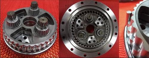
Figure 7 Components of 2KV type cycloid speed reducer
Table 1 Basic design parameters of cycloid-pin gear pair

According to Eq. (14), the backlash between the cycloid gear teeth and their mating pins that potentially share the applied torque is calculated at 45��and 120��crankshaft angles, as shown in Figure 8. Under the unloaded condition, there is only one tooth pair in rigid contact due to the tooth profile modification where the backlash is zero arc second on pin No.17 and No.25 for 45��and 120��crankshaft angles, respectively. The rest of tooth pairs show different degrees of backlash angles.
Figures 9 and 10 show the Hertzian contact stiffness and loads distributed among contacting tooth pairs at 45�� and 120�� crankshaft angles. It can be seen that the stiffness among contacting tooth pairs are different due to their different loads and relative curvature radii at contact points. For this case, there are 10 tooth pairs transferring the applied torque, and different tooth pairs will come into contact as the crankshaft rotates.
Figure 11 shows that the number of tooth pairs in contact and gear ratio vary periodically as the crankshaft rotates due to the tooth profile modification and contact deformation. It can be seen that tooth pairs are in contact between 10 and 11 alternately, and the peak-to-peak value of gear ratio is 0.55. This variation of gear ratio will cause the torque ripple, which should be avoided in practical applications.

Figure 8 Backlash at 45�� (a) and 120�� (b) crankshaft angles

Figure 9 Hertzian contact stiffness among contacting tooth pairs:

Figure 10 Loads distributed among contacting tooth pairs:

Figure 11 Number of tooth pairs in contact (a) and gear ratio (b)
As shown in Figures 12 and 13, with a constant torque, the TMS and LTE vary periodically as the crankshaft rotates with the mean values of 1.86��106 N��m/rad and �C23.34 (��), respectively. They are periodic with the angle between two adjacent pins, which is 9�� in this case. Their peak-to-peak values are 1.79��105 N��m/rad and 1.08 (��) respectively due to the changes of tooth contact number and contact position. Based on the fast Fourier transform (FFT) analysis, it is observed that the first harmonic order is predominant for both TMS and LTE.
4.1 Effects of tooth profile modifications
To investigate the effects of pin radius and pin position modifications, their absolute values of modification amounts are varied from 0 to 20 ��m with an increment of 2.5 ��m, as shown in Figure 14. For both modifications, the mean values of TMS decrease rapidly and then gradually as their absolute values increase, while the mean values of LTE increase exactly proportional to the modification amounts, meaning the increasing lost motion of the speed reducer. It also indicates that under the same modification amount, the pin radius modification is beneficial to obtain higher torsional stiffness but in the cost of the positioning accuracy of the cycloid speed reducer, compared with the pin position modification.
Figure 15 shows the variations of Hertzian contact stiffness and load sharing factor along half tooth profile with the absolute values of modification amounts from 0 (no modification) to 20 ��m with an increment of 5 ��m for both modifications, respectively. For the case without tooth profile modification, the range of crankshaft angle from 0�� to 180�� stands for the half tooth profile in contact with the mating pins. It is observed that a small variation in Hertzian contact stiffness appears due to the variation of relative curvature radii of the tooth pair. The load sharing factor of one tooth pair varies smoothly since there is no abrupt change of the number of contacting tooth pair. However, in presence of tooth profile modifications, the area of tooth profile in contact decreases significantly as the modification amounts increase. As a result, sharper changes of Hertzian contact stiffness happen to the changeover regions of the relative curvature radii of tooth pairs. The load sharing factor along half tooth profile increases and fluctuates, which can be explained by the fact that a larger profile modification causes more reduction and abrupt change of the number of contacting tooth pairs. By comparing the two modifications, their influences on Hertzian contact stiffness are similar. While the load sharing factor for pin radius modification shows slightly smaller than that for pin position modification due to its larger area of tooth profile in contact.
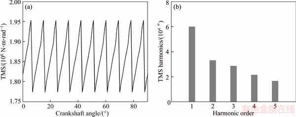
Figure 12 Time-varying torsional mesh stiffness (a) and its harmonics (b)

Figure 13 Time-varying loaded transmission error (a) and its harmonics (b)
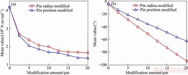
Figure 14 Effect of tooth profile modification on mean values of torsional mesh stiffness (a) and loaded transmission error (b)
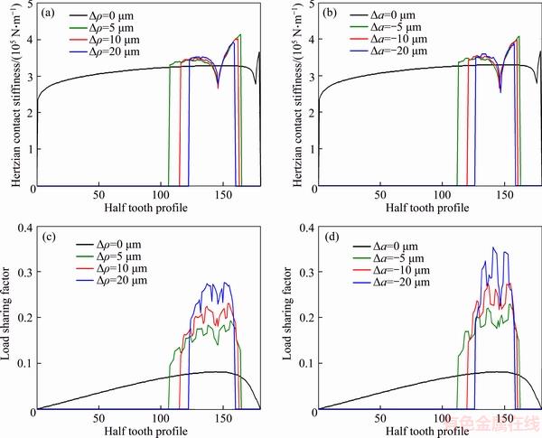
Figure 15 Variations of Hertzian contact stiffness (a, b) and load sharing factor (c, d) along half tooth profile with modification amounts
4.2 Effects of applied torque levels
The applied torque can cause the overall meshing characteristics to change, especially altering the load distribution. For both modifications, the mean values of TMS and LTE are directly related to the levels of applied torque, as shown in Figure 16. They increase dramatically as the increase of applied torque. Similar to previous cases, under the same applied torque level, the pin radius modification shows larger torsional mesh stiffness and higher loaded transmission error than that of pin position modification.
Figure 17 shows the variations of Hertzian contact stiffness and load sharing factor along half tooth profile with four applied torque levels between 40 and 280 N��m. It can be seen that the areas of tooth profile in contact and the Hertzian contact stiffness increase as the increase of applied torque. While the load sharing factor tends to decrease. This can be explained by the fact that more numbers of tooth pairs and larger areas of tooth profile are in contact due to the tooth contact deformation as the torque increases. It is of benefit to reduce the load on one tooth and improve the contact strength of gear pairs. This is also the reason why the cycloid drive has the high overload capability. It is also observed that the load sharing factor for pin radius modification is slightly smaller than that for pin position modification due to its larger tooth profile areas in contact.

Figure 16 Effect of applied torque on mean values of torsional mesh stiffness (a) and loaded transmission error (b)

Figure 17 Variations of Hertzian contact stiffness (a, b) and load sharing factor (c, d) along half tooth profile with applied torque levels:
4.3 Effects of eccentricity errors
The eccentricity error is an important parameter to be controlled during the manufacturing and assembly processes. It can change the contact condition of the cycloid-pin gear pair due to the translation of cycloid gear in the eccentric direction. Figure 18 shows the variations of mean values of TMS and LTE with eccentricity errors from �C4 to 4 ��m with an increment of 2 ��m. It is observed that the eccentricity error has significant effects on the TMS, which will be increased or decreased by the negative and positive eccentricity errors. This indicates that eccentricity errors should be significantly considered during the design and analysis of cycloid speed reducer. For both modifications, the LTE tends to increase as the eccentricity error varies from negative error to positive error. Similar to previous cases, under the same eccentricity error, the LTE for pin radius modification is larger than that for pin position modification.
Figure 19 shows the variations of Hertzian contact stiffness and load sharing factor along half tooth profile with eccentricity errors. In the presence of eccentricity errors, the areas of tooth profile in contact change dramatically and the discontinuous tooth contact is observed at ��e=4 ��m, which leads to larger Hertzian contact stiffness and load sharing factor for both tooth profile modifications, which will deteriorate the load capability of the gear pair. It can be seen that the negative eccentricity error that reduces the central distance between the cycloid gear and ring gear shows a better load distribution characteristic in this case.
5 Conclusions
A new analytical mesh stiffness model of cycloid-pin gear pair is proposed with considering the tooth profile modification and eccentricity error. The unloaded tooth contact analysis is applied to determining the time-varying mesh parameters. An iterative numerical algorithm is proposed based on the nonlinear Hertzian contact theory where the contact stiffness of single tooth pair depends on the contact force and geometry. Then, the analytical model is used to perform a detailed parametric study on the influence of tooth profile modifications, applied torque levels and eccentricity errors. According to the analysis, some conclusions can be drawn:
1) Pin radius and pin position modifications were both found to reduce the mean value of torsional mesh stiffness and increase the loaded transmission error, and thus should be included for accurate mesh stiffness prediction.
2) The torsional mesh stiffness and the loaded transmission errors can be optimized with proper selection of tooth profile modifications.

Figure 18 Effect of eccentricity error on mean values of torsional mesh stiffness (a) and loaded transmission error (b)

Figure 19 Variations of Hertzian contact stiffness (a, b) and load sharing factor (c, d) along half tooth profile with eccentricity errors:
3) Increasing the applied torque increases the number of tooth pairs and the tooth profile areas in contact, which provides a better load distribution characteristic. As a result, the mean values of torsional mesh stiffness and loaded transmission error tend to increase.
4) The presence of the eccentricity errors can influence the areas of tooth profile in contact, leading to the discontinuous tooth contact and increase the load sharing factor, which will deteriorate the load capability of the gear pair.
Further experimental studies will be performed to investigate the lost motion and dynamic characteristic of the prototype cycloid speed reducer in order to tune the analytical model and to assist the optimization of its precision, vibration and noise levels.
References
[1] LI S T. Design and strength analysis methods of the trochoidal gear reducers [J]. Mechanism and Machine Theory, 2014, 81: 140�C154. DOI: 10.1016/j.mechmachtheory. 2014.07.001.
[2] CHEN Bing-kui, ZHONG Hui, LIU Jing-ya, LI Chao-yang, FANG Ting-ting. Generation and investigation of a new cycloid drive with double contact [J]. Mechanism and Machine Theory, 2012, 49: 270�C283. DOI: 10.1016/ j.mechmachtheory.2011.10.001.
[3] TRAN T L, PHAM A D, AHN H J. Lost motion analysis of one stage cycloid reducer considering tolerances [J]. International Journal of Precision Engineering and Manufacturing, 2016, 17: 1009�C1016. DOI: 10.1007/s12541- 016-0123-8.
[4] KUMAR N, KOSSE V, OLOYEDE A. A new method to estimate effective elastic torsional compliance of single-stage cycloidal drives [J]. Mechanism and Machine Theory, 2016, 105: 185�C198. DOI: 10.1016/j.mechmachtheory.2016.06. 023.
[5] CHEN Zai-gang, SHAO Yi-min. Mesh stiffness calculation of a spur gear pair with tooth profile modification and tooth root crack [J]. Mechanism and Machine Theory, 2013, 62: 63�C74. DOI: 10.1016/j.mechmachtheory.2012.10. 012.
[6] CHEN Bing-Kui, FANG Ting-ting, LI Chao-Yang, WANG Shu-yan. Gear geometry of cycloid drives [J]. Science in China Series E: Technological Sciences, 2008, 51: 598�C610. DOI: 10.1007/s11431-008-0055-3.
[7] BLAGOJEVIC M, MARJANOVIC N, DJORDJEVIC Z, STOJANOVIC B, DISIC A. A new design of a two-stage cycloidal speed reducer [J]. Journal of Mechanical Design, 2011, 133: 085001. DOI: 10.1115/1.4004540.
[8] SHIN J H, KWON S M. On the lobe profile design in a cycloid reducer using instant velocity center [J]. Mechanism and Machine Theory, 2006, 41: 596�C616. DOI: 10.1016/ j.mechmachtheory.2005.08.001.
[9] LI Xuan, LI Chao-yang, WANG Ya-wen, CHEN Bing-kui, LIM T C. Analysis of a cycloid speed reducer considering tooth profile modification and clearance-fit output mechanism [J]. Journal of Mechanical Design, 2017, 139: 033303. DOI: 10.1115/1.4035541.
[10] BLANCHE J G��YANG D C H. Cycloid drives with machining tolerances [J]. Journal of Mechanisms, Transmissions, and Automation in Design, 1989, 111: 337�C 344. DOI: 10.1115/1.3259004.
[11] IVANOVI L, DEVED
 I G, UKOVI S, MIRI N. Modeling of the meshing of trochoidal profiles with clearances [J]. Journal of Mechanical Design, 2012, 134: 041003. DOI: 10.1115/1.4005621.
[12] SENSINGER J W. Unified approach to cycloid drive profile, stress, and efficiency optimization [J]. Journal of Mechanical Design, 2010, 132: 024503. DOI: 10.1115/1.4000832.
[13] ZHU Cai-chao, SUN Zhang-dong, LIU Huai-ju, SONG Chao-sheng, GU Zong-lin. Effect of tooth profile modification on lubrication performance of a cycloid drive [J]. Proceedings of the Institution of Mechanical Engineers, Part J: Journal of Engineering Tribology, 2015, 229: 785�C794. DOI: 10.1177/1350650115570402.
[14] MIHAILIDIS A, ATHANASOPOULOS E, AGOURIDAS K. EHL film thickness and load dependent power loss of cycloid reducers [J]. Proceedings of the Institution of Mechanical Engineers, Part C: Journal of Mechanical Engineering Science, 2015, 230: 1303�C1317. DOI: 10.1177/ 0954406215612815.
[15] WEI Bo, WANG Jia-xu, ZHOU Guang-wu, YANG Rong-song, ZHOU Hong-jun, HE Tao. Mixed lubrication analysis of modified cycloidal gear used in the RV reducer [J]. Proceedings of the Institution of Mechanical Engineers, Part J: Journal of Engineering Tribology, 2015, 230: 121�C134. DOI: 10.1177/1350650115593301.
[16] XU Li-xin, YANG Yu-hu. Dynamic modeling and contact analysis of a cycloid-pin gear mechanism with a turning arm cylindrical roller bearing [J]. Mechanism and Machine Theory, 2016, 104: 327�C349. DOI: 10.1016/ j.mechmachtheory.2016.06.018.
[17] HSIEH C F. Dynamics analysis of cycloidal speed reducers with pinwheel and nonpinwheel designs [J]. Journal of Mechanical Design, 2014, 136: 091008. DOI: 10.1115/ 1.4027850.
[18] KIM K H, LEE C S, AHN H J. Torsional rigidity of a cycloid drive considering finite bearing and hertz contact stiffness [C]// Proceedings of the ASME 2009 International Design Engineering Technical Conferences & Computers and Information in Engineering Conference. San Diego: American Society of Mechanical Engineers, 2009: 125�C130. DOI: 10.1115/detc2009-87092.
[19] ZHANG Da-wei, WANG Gang, HUANG Tian. Dynamic formulation of RV reducer and analysis of structural parameters [J]. Journal of Mechanical Engineering, 2001, 37: 69�C74. DOI: 10.3901/jme.2001.01.069. (in Chinese)
[20] LIU Jing-ya, MATSUMURA S, CHEN Bing-kui, HOUJOH H. Torsional stiffness calculation of double-enveloping cycloid drive [J]. Journal of Advanced Mechanical Design, Systems, and Manufacturing, 2012(6): 2�C14. DOI: 10.1299/ jamdsm.6.2.
[21] HE Wei-dong, LI Li-xing, LI Xin. New optimized tooth-profile of cycloidal gear of high precision rv reducer used in robot [J]. Journal of Mechanical Engineering, 2000, 36: 51�C55. DOI: 10.3901/jme.2000.03.051. (in Chinese)
[22] GORLA C, DAVOLI P, ROSA F, LONGONI C, CHIOZZI F, SAMARANI A. Theoretical and experimental analysis of a cycloidal speed reducer [J]. Journal of Mechanical Design, 2008, 130: 112604. DOI: 10.1115/detc2007-34098.
[23] LIN W S, SHIH Y P, LEE J J. Design of a two-stage cycloidal gear reducer with tooth modifications [J]. Mechanism and Machine Theory, 2014, 79: 184�C197. DOI: 10.1016/j.mechmachtheory.2014.04.009.
[24] LITVIN F L, FUENTES A. Gear geometry and applied theory (second edition) [M]. New York: Cambridge University Press, 2004: 68-77. DOI: 10.1017/ cbo9780511547126.015.
[25] LITVIN F L, FENG P H. Computerized design and generation of cycloidal gearings [J]. Mechanism and Machine Theory, 1996, 31: 891�C911. DOI: 10.1016/0094- 114x(95)00115-f.
[26] DEMENEGO A, VECCHIATO D, LITVIN F L, NERVEGNA N, MANC S. Design and simulation of meshing of a cycloidal pump [J]. Mechanism and Machine Theory, 2002, 37: 311�C332. DOI: 10.1016/s0094- 114x(01)00074-x.
[27] JOHNSON K L. Contact mechanics [M]. Cambridge: Cambridge University Press, 1987: 84�C104.
(Edited by HE Yun-bin)
���ĵ���
���dz���������ƫ�ľ����İ������ֳ��ָ����ϸնȼ���
ժҪ���������ּ�����������ṹ���ա������ȴ�߸��Ե��ŵ㣬���㷺Ӧ���ڹ�ҵ�����ֵ����ϸն��Ǹ�ȷ�Գ��ֶ���ѧģ�͵Ĺؼ�������Ȼ��������û�м���������ֳ��ָ����ϸնȵķ���ģ�͡�������������ָ���϶ȷ�����������Լ����Ϲ����ж�ݽӴ����εĸ����ԡ����Ŀ��dz���������ƫ�ľ�����Ӱ�죬����˼���������ֳ��ָ����ϸնȵ��·����������ֳݽӴ�����������Ժ��ȽӴ����ۣ��ֱ�ȷ���˰������ֳ��ָ���ʱ�����ϲ������غɷֲ��������ڵ��ݶԵĽӴ��ն��Լ���ݶԵ�Ťת�նȵ�ȷ���㡣ͨ����ϸ�IJ�����������ʾ�˳������Ρ�Ӧ��ת�غ�ƫ�ľ��Ťת���ϸնȡ����ش��������ȽӴ�Ӧ�����غɷֲ����ӵ�Ӱ�졣��ģ�Ϳ����ڶ������ּ������Ļز��붯̬���ԵĽ�һ���о����������Ż��䴫�����ȡ����������ȼ���
�ؼ��ʣ��������ּ����������ϸնȣ��ֳݽӴ��������غɷֲ�������
Foundation item: Project(51575062) supported by the National Natural Science Foundation of China; Project(51605049) supported by the National Natural Science Foundation for Young Scholar of China; Project(BA2015177) supported by the Science and Technology Achievements Transformation Program of Jiangsu Province of China
Received date: 2017-02-21; Accepted date: 2017-04-03
Corresponding author: CHEN Bing-kui, PhD, Professor; Tel: +86�C23�C65106247; E-mail: bkchen@cqu.edu.cn; ORCID: 0000-0002- 5790-0670
Abstract: Cycloid speed reducers are widely used in many industrial areas due to the advantages of compact size, high reduction ratio and high stiffness. However, currently, there are not many analytical models for the mesh stiffness calculation, which is a crucial parameter for the high-fidelity gear dynamic model. This is partially due to the difficulty of backlash determination and the complexity of multi-tooth contact deformation during the meshing process. In this paper, a new method to calculate the mesh stiffness is proposed including the effects of tooth profile modification and eccentricity error. The time-varying mesh parameters and load distribution of cycloid-pin gear pair are determined based on the unloaded tooth contact analysis (TCA) and the nonlinear Hertzian contact theory, allowing accurate calculations of the contact stiffness of single tooth pair and the torsional stiffness of multi-tooth pairs. A detailed parametric study is presented to demonstrate the influences of tooth profile modification, applied torque and eccentricity error on the torsional mesh stiffness, loaded transmission error, Hertzian contact stiffness and load sharing factor. This model can be applied to further study the lost motion and dynamic characteristics of cycloid speed reducer and assist the optimization of its precision, vibration and noise levels.
