
Trans. Nonferrous Met. Soc. China 24(2014) 806-815
Fracture evolution around pre-existing cylindrical cavities in brittle rocks under uniaxial compression
Xing-dong ZHAO1,2, Hong-xun ZHANG1, Wan-cheng ZHU1
1. College of Resources and Civil Engineering, Northeastern University, Shenyang 110819, China;
2. State Key Laboratory for Geomechanics and Deep Underground Engineering, China University of Mining and Technology, Beijing 100083, China
Received 4 July 2013; accepted 21 November 2013
Abstract:
The development of fracture around pre-existing cylindrical cavities in brittle rocks was examined using physical models and acoustic emission technique. The experimental results indicate that when granite blocks containing one pre-existing cylindrical cavity are loaded in uniaxial compression condition, the profiles of cracks around the cavity can be characterized by tensile cracking (splitting parallel to the axial compression direction) at the roof-floor, compressive crack at two side walls, and remote or secondary cracks at the perimeter of the cavity. Moreover, fracture around cavity is size-dependent. In granite blocks containing pre-existing half-length cylindrical cavities, compressive stress concentration is found to initiate at the two sidewalls and induce shear crack propagation and coalescence. In granite blocks containing multiple parallel cylindrical cavities, the adjacent cylindrical cavities can influence each other and the eventual failure mode is determined by the interaction of tensile, compressive and shear stresses. Experimental results show that both tensile and compressive stresses play an important role in fracture evolution process around cavities in brittle rocks.
Key words:
cylindrical cavity; fracture evolution; uniaxial compression; acoustic emission event location; slabbing;
1 Introduction
As underground excavations progress into deeper and more complex geological environments, the eventual and ultimate limitation in all mining is depth [1]. Excavation-induced macroscale fractures, such as roof fall, side wall slab and rock burst [2-5], can be often observed in the deep high-stressed hard-rock mines, occurring extensively in the side walls of underground working face. Understanding of the failure modes around cavities in brittle rocks under compressive loading conditions becomes more and more important in searching solutions to the problem that mining activity meets [6].
In laboratory loading uniaxial compressive stress conditions, the fracture patterns of rock specimens containing a circular cavity may involve three different failure processes: primary fracture at the tensile stress concentration, secondary fracture at positions inside the rock abutments, and side wall slabbing at the concentration of compressive stress [7,8]. HOEK and BROWN [2] used photoelastic film to demonstrate the presence of remote areas of tension about a circular opening. LAJTAI et al [9] used plaster models to demonstrate the combination fracture of slabbing- crushing and the shear fracture with the failure process in the compression zone causing the collapse of the cavity. LAJTAI et al [10] employed the physical method to study the development of fractures around cavities. MARTIN et al [11] carried out a similar test in Lac du Bonnet granite and found three types of fractures around a 60 mm diameter circular opening. The breakout occurred in the maximum shear stress region around the boundary of the circular opening, which, for plane-strain conditions, was given by JAEGER and COOK [12]. However, like other classic physical models, the fracture patterns in the rock samples were incapable of characterizing the entire fracture process, which involved the initiation, propagation, and coalescence of micro-cracks through the formation of a full-scale macro-crack.
Some numerical solutions have been developed to illustrate the evolution process of fractures from the micro-cracks existing around openings. ZHU et al [13,14] and TANG et al [15] applied the rock failure process analysis (RFPA) code to model the progressive fracturing around a circular opening under uniaxial compression and the acoustic emission (AE) distributions, where fracturing patterns and the maximum shear stress distributions were presented. FAKHIMI et al [16] used the particle flow code (PFC) based on the distinct element method, to simulate the localization behavior of rock samples within a circular cavity and to reproduce the damage zone. These numerical results could be used with more confidence to examine the nature of damage and failure in rocks. However, these codes have rarely been reported to simulate the fracture evolution of rock samples with half-length cylindrical excavations or with three cylindrical cavities.
To enable good comparison between the previous studies, 15 granite specimens with cylindrical cavities of different diameters were examined to study crack initiation, propagation and coalescence of cylindrical cavities on the failure patterns of rock specimens. Two other groups of granite samples in the panel, containing a half-length cylindrical cavity or three cylindrical cavities, were also used to study their failure patterns. The aim of this study is to identify the evolution, interaction and development of fractures around cavities subjected to uniaxial compression and to interpret their failure patterns.
2 Experimental
2.1 Physical specimen model test
Twenty five medium-grained brittle hard granite blocks with dimensions 100 mm��100 mm��200 mm were cut and ground to accurate size based on the recommendation of the ISRM [17]. All the specimens have a height-to-width ratio of 2. Parallelism between top and bottom faces of each specimen is within an error of 0.02 mm. The fracture evolution in granite samples with pre-existing single cylindrical cavities was experimentally modeled to examine the influence of cavity diameter on crack evolution behavior. Fifteen blocks of granite, divided into 3 groups of 5 blocks each, were prepared with cylindrical cavities with diameters of 20, 28 and 38 mm. This was the uniform of the fifteen rock samples. The compressive strength averaged 112 MPa while the tensile strength averaged 12 MPa. All of the specimens with cylindrical cavities were loaded under uniaxial compression. Each cuboid granite specimen was equipped with four axial and lateral strain gauges attached on the surface of the specimens and positioned directly in direction of tensile/ compressive stress concentration areas (Fig. 1).
2.2 Testing apparatus
The uniaxial compression tests were carried out with a 3000 kN capacity testing machine (Fig. 2), which used displacement control featuring electromechanical controllers with three control channels. The loading system recorded the values of the load and displacement and drew the curve of load-displacement instantaneously. The specimens were loaded to fail at a minimum loading speed of 0.05 mm/min. Eight acoustic emission (AE) transducers were glued to different points along the outer surface of specimens.
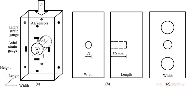
Fig. 1 Specimen with different cylindrical cavities in diameters of 20, 28 and 38 mm, strain gauges, acoustic emission monitoring system and loading conditions (a), cuboid granite samples consisting of half-length cylindrical cavity with 20 mm in diameter and 50 mm in length (b), and cuboid granite samples containing three cylindrical cavities with diameters of 28 mm (top and bottom) and 20 mm (center) (c)
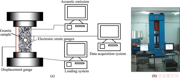
Fig. 2 Schematic of strain gauge, acoustic emission instrumentation and data collection systems (a) and photograph of testing apparatus (b)
2.3 Acoustic emission monitoring equipment
An 8-channel, high-speed AE signal acquisition and analyzing system, with a sampling rate of 10 MHz, a 40 dB pre-amplification (1220A-AST) and a 20 dB gain, acquired and recorded the characteristics of AE and demonstrated their temporal and spatial distribution during the rupture-brewing process. The threshold was set at 100 dB to eliminate a high signal-to-noise ratio. The AE signals were acquired by 8 transducers with frequency sensitivities from 125 Hz to 750 kHz. Using a Geiger location algorithm [18-21], AE event location was tested from the first arrival time of p-waves detected using the AE sensors. The AE monitoring system not only digitized the signal waveform, but also stored features of each signal.
3 Results and analysis
Three types of models containing cylindrical cavities were tested to observe the development of fracture patterns and to collect quantitative data on the total crack length as a function of the increasing uniaxial load. The following three sections depict the crack initiation, propagation and coalescence of granite specimens containing cylindrical cavities: increasing compressive stress, development of primary shear, and remote cracking. The fracture evolution was studied for three groups of granite samples containing cylindrical cavities under the uniaxial compressive conditions.
3.1 Crack evolution in granite specimens with different diameters of cylindrical cavities
Three cases of experiments were carried out. For case 1, the cuboid specimen has a cylindrical cavity of 20 mm diameter located in the middle height of the specimen; case 2, the cuboid specimen has a cylindrical cavity of 28 mm diameter located in the middle height of the specimen; case 3, the cuboid specimen has a cylindrical cavity of 38 mm diameter located in the middle height of the specimen.
The AE events locations during the failure process are presented in Fig. 3. Only the AE events that could be located with an error less than 5 mm were selected for the source characterization. In case 1, it can be clearly seen that many AE events were concentrated around the potential tensile damage zones. Therefore, the compliant behavior of the rock was responsible for the initiation of the cracks that developed in the roof-floor of the cavity. The tensile fracture zones eventually reached the vertical upper and lower boundaries. In case 2, it can be clearly seen that the AE events were mainly concentrated around the perimeter of the cylindrical cavity when the vertical stress reached 35 MPa. The AE events, mainly concentrated at the roof-floor, gradually formed clusters, thereby initiating the tensile fracture and slabbing. Although many AE events were recorded outside the zone of rock mass surrounding the cavity, these AE events were not the active micro-cracks, which were significant because of their effect on the mechanical properties of the rock. At initial stage, it was difficult to predict where the macro-crack would begin in the loading process, because the AE events were discrete in the specimen. When the vertical stress reached 81 MPa, the AE events occurred around certain clusters, and were in a distinct AE active zone that developed in the roof- floor of the cylindrical cavity and the nucleation zone in the specimen. In case 3, the AE active zones were connected to form a large active AE zone that was consistent with the site of the macro-cracks. In contrast, very few localized AE events occurred in the region near the vicinity of cavity wall during the total loading process. With the influence of strong interaction between isolated micro-cracks, these isolated micro-cracks progressively propagated in an unstable manner, and eventually coalesced to form a splitting macro-crack failure.
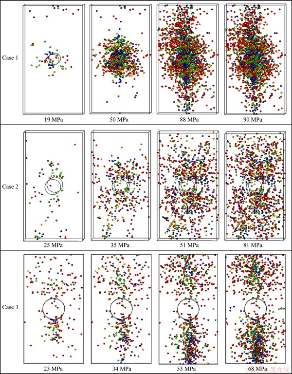
Fig. 3 Distribution of acoustic emission location in granite specimens with pre-existing cylindrical cavities
Figure 4 presents the failure patterns of the specimen containing the smaller pre-existing cylindrical cavity, which failed in a splitting mode (Fig. 4(a)), and its cleavage paralleled the direction of the maximum axial stress [22], whereas the other two specimens failed because of cracks initiated in a shear stress zone. When the diameter of the cylindrical cavity was 28 mm, the failure pattern (Fig. 4(b)) was the remote or secondary fracture at the rock abutment and the side wall slabbing at the compressive stress concentration due to the tensile fracture initiation at the roof-floor [23]. In contrast to the failure pattern of the specimens with a cylindrical cavity of 28 mm in diameter, the specimens with a cylindrical cavity of 38 mm in diameter had failure patterns (Fig. 4(c)) that occurred as tensile cracking in the roof-floor and the V-shaped notch in the side wall. However, their similarity was not perfect. In general, the slabbing occurring in the periphery of the 38 mm diameter cylindrical cavity was much more serious than in the cavity with 28 mm in diameter, and no crack-remote damaged zone in a compressive area can be seen in Fig. 4(c). Whether the deformation induced instability problem in the cylindrical cavity is dependent upon the ratio of the diameter of the cylindrical cavity to the width of the cuboid granite sample, it was demonstrated in the previous detailed description. The fracture nucleation stress and fracture types for all three granite types were size-dependent with size sensitivity being most prominent in the different size ranges.
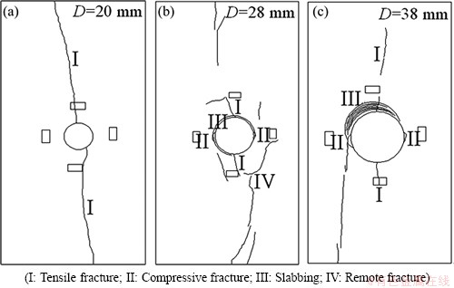
Fig. 4 Fracture distribution of cuboid granite samples containing cylindrical cavities with different diameters
Figure 5 shows the stress-strain curves of granite specimens with cylindrical cavities of different diameters. Tensile stress concentration and the damage initiation were measured by the strain gauges attached along the direction of the fracture with the increasing uniaxial load. The lateral strain was increased with the increase of the cavity size. For specimens with cavity diameter of 20 mm, the tensile stress concentrated at the roof-floor and the compressive stress concentrated at the two sidewalls (Fig. 5). When the axial stress was 50 MPa (with a maximum axial strain of 0.17%), the tensile crack initiated in the roof-floor of the cylindrical cavity. With the increase of axial loading, the tensile crack gradually propagated, nucleated and coalesced, thus leading to instability of the granite samples. The failure pattern was slightly different from previous experimental results [6], which showed no compressive damage at the sidewalls and remote cracks (case 1 in Fig. 3). The pattern of the macroscopic fracture observed at the roof-floor was generally parallel to the direction of the uniaxial compressive load.
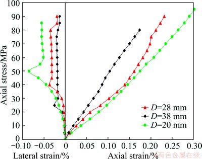
Fig. 5 Axial stress vs axial/lateral strain behavior of specimens with cylindrical cavities
For specimens with cavity diameter of 28 mm and 38 mm, when the axial stresses were 40 MPa and 25 MPa with the maximum axial strains of 0.14% and 0.058%, respectively, the tensile cracks initiated and developed from the roof and floor. With the increase of compressive stress, cracks were initiated approximately adjacent to the termination of the tensile fractures and at some distance from the cylindrical cavity at the roof and floor and the propagation of cracks paralleled to the direction of axial stress. However, the crack did not fulfill the coalescence criterion in the tensile stress concentration. During the propagation of the tensile crack, when axial stress exceeded the compressive strength of the granite specimens, compressive damage was initiated and grew; the damage was also observed at the sidewalls. The resulting damage zone occurring [24] is commonly referred to as a breakout or V-shaped notch (Figs. 4(b) and (c)). The failure around the cavity observed in the granite samples is depicted in Figs. 4(b) and (c), which reveals that the V-shaped notch occurred in a manner similar to that observed in previous studies [25,26]. As the distance from the cavity face increased, the failure zone became wider and deeper. As the axial stress increased, slabbing was first observed in the periphery near the cylindrical cavities with diameters of 28 mm and 38 mm under high stress conditions [27] and then collapsed, leaving dust and small particles (see Figs. 4(b) and (c)) [10,23]. However, the slabbing failure in the case of a cavity diameter of 28 mm at these compressive stress concentrations was no more obvious than that in a 38 mm-diameter cavity. The specimens lost their loading capacity. The remote failure, either tensile or primary, and the sidewalls fractures around a cylindrical cavity of 28 mm in diameter are shown in Fig. 4(b), whereas no remote failure was observed, as shown in Fig. 4(c). Fracture development beyond the stages of the primary tension and normal shear fracture was usually responsible for the eventual collapse of the cylindrical cavities in the specimens.
3.2 Crack evolution in granite samples with half- length cylindrical cavities
To investigate workplace failure behavior of an underground cavity under uniaxial compression, another group of five granite specimens containing pre-existing half-length cylindrical cavities were considered. In this case, the diameter and length of cavities were 20 mm and 50 mm, respectively, as shown in Fig. 1(b). The vertical load was applied at a rate of 20 kN/min and showed a uniaxial compressive strength of 98 MPa, a P-wave velocity of 3850 m/s and a Poisson ratio of 0.24. The AE system was used to monitor the failure process during the total testing process.
The AE events location distributions are presented in Fig. 6. It can be seen that before the vertical stress reached 16 MPa, the AE events were mainly distributed in the upper and bottom boundaries. With loading increasing, the tensile and compressive stress concentrations were located in the roof-floor and two sides of cylindrical cavity. After the axial stress reached 90 MPa, a distinct AE active zone developed in the specimen. Although a few of AE events occurred through the whole specimen, most AE events were clustered near the nucleation zone on the left-hand side of the specimen. The final AE events showed that the AE active zones were connected to form the macro-cracks of the V-shaped notches in the two sidewalls and the shear fracture in the panel. It is likely the damage in the notches and, therefore, the compliant behavior of the rock in this region was responsible for the initiation of the cracks. These rupture zones eventually reached the vertical boundaries [16].
The primary crack and shear fracture of the granite specimens with half-length cylindrical cavities are illustrated in Fig. 7. The most prominent failure zone observed around the cylindrical cavities in the brittle rocks was the region of breakout. This zone formed as a V-shaped notch and was caused by microcracking. The compressive stress damage zone was larger in the area of the side walls than in the roof-floor area of the cylindrical cavities. Under tangential stress conditions, the breakouts occurred in the region of maximum tangential stress around the boundary of the cylindrical opening. One important characteristic of the shear fracture was that it was not a single fracture, but a fracture zone caused by shear damage. In addition to the failure patterns on the surface, the shear fracture at the two side walls could also be observed ahead of the face of the half-length cylindrical cavities.
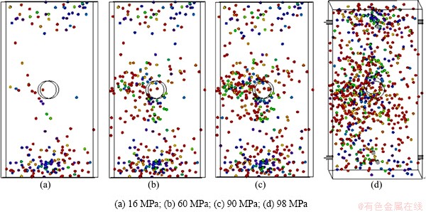
Fig. 6 Distribution of acoustic emission location in cuboid granite sample containing half-length cylindrical cavity with 20 mm in diameter and 50 mm in length
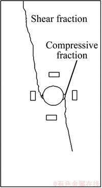
Fig. 7 Fracture distribution of cuboid granite sample containing half-length cylindrical cavity with 20 mm in diameter and 50 mm in length
The axial stress vs axial/lateral strain and the accumulative AE events curves are shown in Fig. 8. Before the axial stress reached 16 MPa, the stress (tensile in the roof-floor; compressive in the side walls) was concentrated on the periphery of the cylindrical cavity [28,29], and observed through the data provided by the strain gauges. The lateral strain began to increase more rapidly than the axial strain. Existing micro-cracks closed to the point where nearly all the strains could not be recovered upon unloading (Stage I). Tensile failure was first noticed in the roof-floor region, whereas compressive damage was first initiated in the side walls of the five testing granite specimens when the axial stress exceeded the uniaxial compressive strength of the specimens. Subsequently, more compressive damage was observed in the two side walls, which eventually led to the primary (compressive) failure in two sides of the cylindrical cavity (Stage II). The increase in axial stress and the high compressive stress were concentrated at the side walls when the axial stress reached 90 MPa. V-shaped (in echelon) fractures caused by micro- cracking (Stage III) resulted in localized failure and occurred extensively in the side walls. After the propagation of the primary compressive fracture, any increase in the axial stress led to continuous initiation and propagation of shear fractures. Shear fracture was observed in locations remote from the perimeter of the cylindrical cavity. These shear fractures were associated with the redistribution of tensile stress towards the side walls of the cavity. The axial and lateral strains caused unstable changes. Shear fractures propagated from the V-shaped notch to the macroscopic fracture and they propagated away from the cylindrical cavity (Stage IV). From Fig. 8, it can be inferred that the remote fracture was also caused by the tensile fracture. The granite specimen lost its strength, and the main crack broke. The eventual collapse of the circular cavities in the specimens was caused by the concentration, initiation, propagation and coalescence of the shear stress.
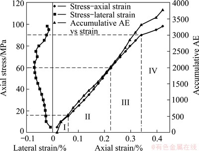
Fig. 8 Axial stress vs strain, accumulative acoustic emission and lateral strain behaviors of cuboid granite samples containing half-length cylindrical cavity with 20 mm in diameter and 50 mm in length
3.3 Crack evolution in granite specimens with multiple cylindrical cavities
To study the influence of the interaction between cavities close to each other, the specimens containing an array of three circular cavities arranged in vertical lines were tested. Five granite specimens with three circular cavities (the diameters of two pre-existing cylindrical cavities were 28 mm at the top and bottom of the specimens and one pre-existing cylindrical cavity was 20 mm in diameter in the center (Fig. 1(c)) were loaded under uniaxial compression. Sixteen electric strain gauges with serial numbers A-H were instrumented on the specimens to measure the axial and lateral strains (Fig. 9).
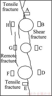
Fig. 9 Axial stress vs axial/lateral strain behavior of granite samples with three pre-existing cylindrical cavities
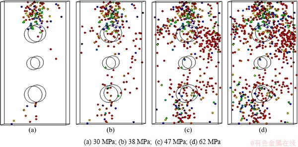
Fig. 10 Distribution of acoustic emission location in granite specimens with pre-existing cylindrical cavities
Figure 10 shows the AE events location distribution during the total loading process. From Fig. 10, it is clear that very few localized AE events occurred at the upper edge of the granite specimens during the early stage of loading when the vertical stress reached 30 MPa. The results showed that the tensile crack initiated in the roof of the pre-existing cylindrical cavity. With load increasing, more of the AE occurred, and the AE active zones were connected to form a larger AE active zone. It was found to be consistent with the occurrence of macro-cracks.
Figure 9 shows the ultimate failure patterns and fracture distribution for the granite specimens containing multiple pre-existing cylindrical cavities. The coalescence stress was 96 MPa. At first, the cracks grew quickly. When the tips of the cracks were near the ends of the specimen, the propagation then slowed down, or sometimes stopped, because of the boundary effect. When the shear stress in the area between the cavity and the free boundary of the specimen was sufficiently high, shear failure occurred between the cavity and the free boundary (Fig. 9). It is interesting to note that no cracks nucleated from the central cylindrical cavity arranged in the vertical line. The tensile stress decreased around the central cavity, which may have been caused by the presence of the free specimen boundaries. The crack growth can be seen more clearly in the following loading stage in the specimens containing multiple cylindrical cavities. The interaction between cavities and their coalescence was more complicated than that discussed above, and the central, smaller cavity became the direction of the splitting failure.
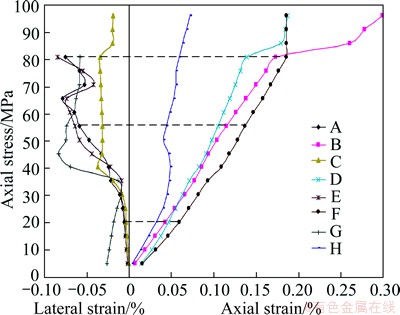
Fig. 11 Axial stress vs axial/lateral strain behavior of granite samples with three pre-existing cylindrical cavities
Figure 11 shows the curves of axial stress vs axial/lateral strain of granite specimens with pre-existing cylindrical cavities. As shown in Fig. 11, when the specimens were subjected to a uniaxial compressive stress, the axial strain contracted and the lateral strain extended. At low stresses (less than 32 MPa), the axial and lateral strain steadily propagated, but the axial strain increased more rapidly than the lateral strain. As a result of the changing axial/lateral strain, the tensile stress was concentrated in the roof-floor and the compressive stress was concentrated at the side walls. With the axial stress increasing, the lateral strain changed more than the axial strain ratio. When the tensile stress exceeded the tensile strength of specimens, tensile cracks initiated in the roof- floor. These cracks were usually manifested by small changes in the position and orientation of fracture surfaces at the roof of the top cavity and the floor of the bottom cavity; however, no damage initiation could be observed surrounding the central smaller cavity. When specimens were subjected to a higher stress (��=66.5 MPa), the lateral strain at the roof-floor of the pre-existing cylindrical cavity attained the maximum value, and the propagation of the tensile crack started to stabilize. Meanwhile, high compressive stresses were concentrated at the sidewalls, where some small flakings could be observed at the sidewalls of the upper and central cavities. After the axial stress reached 82 MPa, the slight compressive stress increased the number of tensile fracture ��breakthrough�� from the upper and lower cavity to the top and bottom faces, and the shear fractures closed at the sidewalls and floor of the central cavity. Although the compressive failure was initiated purely by local fracture, the cracks still appeared to propagate, yet the compressive cracks could not affect the failure patterns of the specimens. The remote cracks appeared in the compressive stress zones and were parallel to the axial stress direction. The failure was not localized in the circular cavity, but was instead within finite regions determined by the geometry. The fracture evolution was influenced more and more by the presence of the adjacent cylindrical cavities and the orientation of their crack propagations relatively to another. The eventual failure patterns were created by the interaction of tensile and shear stress.
4 Conclusions
1) A critical axial stress is required to initiate crack growth, which depends on the initial pre-existing cylindrical diameter. Cracks nucleate more readily from larger cavities than from smaller cavities; the uniaxial maximum stress in the specimens decreases with the increasing cavity size.
2) V-shaped cracks are observed to initiate from two sides of the specimen containing a half-length cylindrical cavity, and the nucleated shear cracks propagate away from the cavity.
3) In a specimen that containing multiple cylindrical cavities with different diameters, cracks initiate, propagate and coalesce in more complicated patterns, which indicates the existing of interaction between the crack and the free surface of specimen.
4) The locations of the AE events, determined in the test experiment, clearly show the evolution of damage and failure process. It is found that the acoustic emission is not completely in the area of the rupture zone, denoting the damage zone distribution near the observed fractures.
References
[1] KUIJPERS J. Fracturing around highly stressed excavations in brittle rock [J]. The Journal of the South African Institute of Mining and Metallurgy, 2000, 10: 325-331.
[2] HOEK E, BROWN E T. Underground excavations in rock [M]. London: Institute of Mining and Metallurgy, 1980: 527.
[3] WHITE B G. Shear mechanism for mining-induced fractures applied to rock mechanics of coal mines [C]//Proceedings of the 21st International Conference on Ground Control in Mining. Morgantown, WV: West Virginia University, 1999: 328-334.
[4] EWY R T, COOK N G W. Deformation and fracture around cylindrical openings in rock. I. Observations and analysis of deformations [J]. International Journal of Rock Mechanics and Mining Sciences, 1990, 27(5): 387-407.
[5] EWY R T, COOK N G W. Deformation and fracture around cylindrical openings in rock. II. Initiation, growth and interaction of fractures [J]. International Journal of Rock Mechanics and Mining Sciences, 1990, 27(5): 409-427.
[6] DZIK E J, LAJTAI E Z. Primary fracture propagation from circular cavities loaded in compression [J]. International Journal of Fracture, 1996, 79: 49-64.
[7] CARTER B J, LAJTAI E Z, YUAN Y. Tensile fracture from circular cavities loaded in compression [J]. International Journal of Fracture, 1992, 57: 221-236.
[8] CARTER B J, LAJTAI E Z, PETUKHOV A. Primary and remote fracture around underground cavities [J]. International Journal Numerical and Analytical Methods in Geomechanics, 1991, 15(1): 21-40.
[9] LAJTAI E Z, LAJTAI V N. The collapse of cavities [J]. International Journal of Rock Mechanics and Mining Sciences, 1975, 12: 81-86.
[10] LAJTAI E Z, CARTER J, DUNCAN E J S. Mapping the state of fracture around cavities [J]. Engineering Geology, 1991, 31: 277-289.
[11] MARTIN C D, READ R S, MARTINO J B. Observations of brittle failure around a circular test tunnel [J]. International Journal of Rock Mechanics and Mining Sciences, 1997, 34(7): 1065-1073.
[12] JAEGER J C, COOK N G W. Fundamentals of rock mechanics [M]. 3rd edition. London: Chapman and Hall, 1979.
[13] ZHU Wan-cheng, LIU Ji-shan, TANG Chun-an, ZHAO Xing-dong, BRADY B H. Simulation of progressive fracturing processes around underground excavations under biaxial compression [J]. Tunneling and Underground Space Technology, 2005, 20: 231-247.
[14] ZHU Wan-cheng, BRUHNS O T. Simulating excavation damaged zone around a circular opening under hydromechanical conditions [J]. International Journal of Rock Mechanics and Mining Sciences, 2008, 45: 815-830.
[15] TANG Chun-an, WONG R H C, CHAU K T, LIN Peng. Modeling of compression-induced splitting failure in heterogeneous brittle porous solids [J]. Engineering Fracture Mechanics, 2005, 72: 597-615.
[16] FAKHIMI A, CARVALHO F, ISHIDA T, LABUZ J F. Simulation of failure around a circular opening in rock [J]. International Journal of Rock Mechanics and Mining Sciences, 2002, 39: 507-515.
[17] BROWN E T. Rock characterization testing and monitoring [C]// ISRM Suggested Methods, ISRM. London: Pergamon Press, 1981: 107-127.
[18] LOCKNER D A. The role of acoustic emission in the study of rock failure [J]. International Journal of Rock Mechanics and Mining Sciences and Geomechanics Abstract, 1993, 30(7): 883-899.
[19] LOCKNER D A, BYERLEE J D, KUKSENKO V, PONOMREV A, SIDORIN A. Quasi-static fault growth and shear fracture energy in granite [J]. Nature, 1991, 350(7): 39-42.
[20] ZHAO Xing-dong, LI Yuan-hui, YUAN Rui-fu, YANG Tian-hong, ZHANG Jian-yong, LIU Jian-po. Study on crack dynamic propagation process of rock samples based on acoustic emission location [J]. Chinese Journal of Rock Mechanics and Engineering, 2007, 26(5): 944-950. (in Chinese)
[21] XU Shuai, LIU Jian-po, XU Shi-da, WEI Jiong, HUANG Wen-bo, DONG Long-bin. Experimental studies on pillar failure characteristics based on acoustic emission location technique [J]. Transactions of Nonferrous Metals Society of China, 2012, 22(11): 2792-2798.
[22] FAIRHURST C, COOK N G W. The phenomenon of rock splitting parallel to the direction of maximum compression in the neighborhood of a surface [C]//Proceeding 1st Congress ISRM. Lisbon: A.A. Balkema, 1996, 1: 687-692.
[23] LAJTAI E Z, CATER B J, DUNCAN E J S. En echelon crack-arrays in potash salt rock [J]. Rock Mechanics Rock Engineering, 1994, 27(2): 89-111.
[24] KAISER P K, GUENOT A, MORGENSTERN N R. Deformation of small tunnels��IV. Behavior during failure [J]. International Journal of Rock Mechanics and Mining Sciences and Geomechanics Abstract, 1985, 22(3): 141-152.
[25] KAISER P K, DIEDERICHS M S, MARTIN C D, STEINER W. Underground works in hard rock tunnelling and mining [C]// Proceedings of Geology Engineering 2000. Melbourne, Australia, Technomic Publishing Co, 2000: 841-926.
[26] MARTIN C D, KAISER P K, MCCREATH D R. Hoek-Brown parameters for predicting the depth of brittle failure around tunnels [J]. Canadian Geotechnique Journal, 1996, 36: 136-151.
[27] STACEY T R. A simple extension strain criterion for fracture of brittle rock [J]. International Journal of Rock Mechanics and Mining Sciences and Geomechanics Abstract, 1981, 18: 469-474.
[28] GOLSHANI A, OKUI Y, ODA M, SUZUKI K. Simulation of damage around a circular opening in rock [C]//11th International Conference of IACMAG. Turin, Italy: Politecnico di Torino & AGI, 2005.
[29] BLAIR S C, COOK N G W. Analysis of compressive fracture in rock statistical techniques: Part I: A non-linear role-based model [J]. International Journal of Rock Mechanics and Mining Sciences, 1998, 35: 837-848.
����ѹ�������º�Բ�ο�������ʯ�Ķ����ݻ�
���˶�1,2���ź�ѵ1�������1
1. ������ѧ ��Դ����ľ����ѧԺ������ 110819��
2. �й���ҵ��ѧ(����) �������ѧ����¹��̹����ص�ʵ���ң����� 100083
ժ Ҫ��Ӧ������ģ�ͺ������似�����о�Ԥ��Բ�ο�������ʯ�Ķ����ݻ����̡�����������ڵ���ѹ�������£�����Բ�ο��������ƻ���Ҫ����Ϊ�ڿ��ײ���ƽ���ڼ��ط���������������ƣ��ڿ��������ѹ�����ƣ��ڿ��ܱ߲���Զ�����ƣ�����������ƻ����гߴ�ЧӦ���Ժ��а볤Բ�Ŀ��ڻ���������������Բ������ڲ���ѹӦ�����У��շ������������Ƶij�ʼ����չ��ͨ���Ժ��ж��ƽ�п������������ƻ���Ҫ������Բ�ο��ڲ���������ѹ������ͬ���õĽ�����������������ѹӦ������ɺ�Բ�ο��������ѵĹؼ����ء�
�ؼ��ʣ�Բ�ο��������ݻ�������ѹ���������䶨λ������
(Edited by Xiang-qun LI)
Foundation item: Projects (51004025, 51174044) supported by the National Natural Science Foundation of China; Project (2011AA060400) supported by the National High-tech Research and Development Program of China; Project (N120501003) supported by Ministry of Education of the People��s Republic of China; Project (LJQ2012024) supported by Department of Education of Liaoning Province, China
Corresponding author: Xing-dong ZHAO; Tel: +86-24-83691093; E-mail: zhaoxingdong@mail.neu.edu.cn
DOI: 10.1016/S1003-6326(14)63129-0
Abstract: The development of fracture around pre-existing cylindrical cavities in brittle rocks was examined using physical models and acoustic emission technique. The experimental results indicate that when granite blocks containing one pre-existing cylindrical cavity are loaded in uniaxial compression condition, the profiles of cracks around the cavity can be characterized by tensile cracking (splitting parallel to the axial compression direction) at the roof-floor, compressive crack at two side walls, and remote or secondary cracks at the perimeter of the cavity. Moreover, fracture around cavity is size-dependent. In granite blocks containing pre-existing half-length cylindrical cavities, compressive stress concentration is found to initiate at the two sidewalls and induce shear crack propagation and coalescence. In granite blocks containing multiple parallel cylindrical cavities, the adjacent cylindrical cavities can influence each other and the eventual failure mode is determined by the interaction of tensile, compressive and shear stresses. Experimental results show that both tensile and compressive stresses play an important role in fracture evolution process around cavities in brittle rocks.
