

Numerical simulation and experimental investigation of two filling methods in vertical centrifugal casting
WU Shi-ping(��ʿƽ)1, LI Chang-yun(������)1, GUO Jing-jie(������)1,
SU Yan-qing (������)1��LEI Xiu-qiao(������)2, FU Heng-zhi(����־)1
1. School of Materials Science and Engineering, Harbin Institute of Technology, Harbin 150001, China;
2. Foundry Co Ltd, First Automobile Group Corporation, Changchun 130011, China
Received 9 November 2005; accepted 5 April 20
Abstract:
A mathematical model of the centrifugal filling process was established. The calculated results show that the centrifugal field has an important influence on the filling process. Moreover, the process of liquid flow and the location of free surface in sprue were simulated based on the Solution Algorithm-Volume of Fraction (SOLA-VOF) technique. In order to verify the mathematical model and computational results, hydraulic simulation experiment was carried out. The results of experiments and numerical simulation indicate the accuracy of mathematical model. Two kinds of filling methods were investigated and the results show that the bottom filling is better than the top filling that can achieve stable filling and reduce defects.
Key words:
titanium alloy; vertical centrifugal casting; hydraulic simulation; numerical simulation; top filling; bottom filling;
1 Introduction
Titanium alloys possesses a high potential for production of work pieces with high strength, mechani- cal properties and high corrosion resistance, which makes them widely applied in aviation, astronavigation and civil fields[1-5]. However, it is well known that titanium alloys are inherently difficult to cast, mainly due to the high activity in molten state and poor fluidity. There are many methods[6-8] to produce titanium alloys, such as gravity casting, pressure casting, centrifugal casting. Only centrifugal casting in vacuum can be used widely. Centrifugal casting can improve the flow rate of alloy melt, save raw material, reduce production cost and can also increase casting precision, and simultaneously the fluidity of titanium alloy is enhanced with increasing the rotational velocity of mold. Now many researchers have devoted to study the cast process of titanium alloy in centrifugal casting. LIU et al[9] pointed out that the superheat of molten metal plays an important role in the full filling of titanium alloy. SHIMIZU and HABU[10] discussed that the surface tension, kinematic viscosity and the temperature difference between the fusion temperature and the mold temperature affect the filling process of titanium alloy significantly. GUO et al[11] have given the analysis of overflow critical value for TiAl based alloy during the process of centrifugal casting. WATANABE et al[12] have indicated that the castings produced by the centrifugal casting machine are significantly better than that produced by the pressure-difference casting. WU et al[13-15] have investigated the casting process and porosity of titanium dental castings with numerical simulation method. LI[16] has pointed out that the path line of liquid in centrifugal conditions is involute. However, few documents report the filling state of titanium alloy in centrifugal field, because the melting and casting of titanium alloy are often carried out in vacuum condition. So, till now there is no complete picture of the filling process of titanium alloys. However, the filling process plays an important role in the casting of such alloys, which will affect the solidification and the formation of defects.
The aim of this paper is to investigate the mold filling process in vertical centrifugal casting. Based on the forces analysis of mold filling in vertical centrifugal casting, the mathematical model for numerical simulation is established and the experiment of hydraulic simulation is investigated. The comparison between the experimental and the numerical results is carried out.2 Mathematical model
2.1 Forces analysis of fluid in vertical centrifugal casting
The flowing of liquid metal can be considered group movement of mass particles. Three kinds of force act on the liquid metal in centrifugal field, including gravity, centrifugal force and Coriolis force. In a rotating system with an angular velocity �� and the distance r between the moving particle and rotating center, the Coriolis acceleration is 2���ء�vr, and the centrifugal acceleration is (r����)����, the gravity acceleration is g. It can be seen from Fig.1 that the mold filling process of centrifugal casting is a composite motion process of fluid under three forces. According to the force analysis and the principle of force composition, the composite force of liquid particle is Fn.
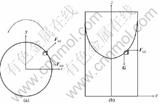
Fig.1 Schematic diagram for forces analysis of liquid
Fce, Fco, G and Fn terms express the forces acting on it and the following relation should be satisfied:
Fce+Fco+G+Fn=0 (1)
where Fco is the coriolis force; Fce is the centrifugal force; G is the gravity; and Fn is the resultant force of above three forces acting on mi.
Therefore, the expression of Fn is obtained:
Fn=Mi(�ء�(�ء�r)-2�ء�vr-g) (2)
2.2 Mathematical model for mold filling of verticalentrifugal casting
A self-developed casting simulation software was used to simulate the mold filling and solidification by solving the Navier-Stokes (fluid flow) and Fourier (heat transfer) equations numerically. Because it was about the hydraulic simulation and the experiment was carried out at room temperature, it doesn��t need to consider the heat transfer during the mold filling process.
Consider the stationary volume element within a fluid moves with a velocity having the components vx, vy, vz and the density of fluid in the engineering is often constant, then the continuity equation[17] reduces to
![]() (3)
(3)
Eqn.(4) is often referred to the Navier-Stokes��s equation. In the form of Eqn.(4), we can recognize it as a statement of Newtonian law in the form of mass (��) ![]() acceleration (dv/dt) equal to the sum of forces, namely, the pressure force (
acceleration (dv/dt) equal to the sum of forces, namely, the pressure force (![]() ), the viscous force (
), the viscous force (![]() ), and the gravity or body force ��g:
), and the gravity or body force ��g:
![]() (4)
(4)
In the rectangular coordinate system, Eqn.(4) can be written as


(5)
In the process of vertical centrifugal casting, gx is x- component accelerated velocity, gy is y-component accelerated velocity and gz is z-component of gravity acceleration.
The mold filling process in vertical centrifugal casting is a transient flow process of fluid with free surface. VOF method is used to calculate the free surface in this paper. The equation of volume of fluid-function is
![]() (6)
(6)
where F is the volume function. The value is unity for cells fully occupied by fluid, zero for empty cells, and between 0 and 1 for surface cells.
3 Results and discussion3.1 Experimental results
The rotational speed range of centrifugal machine used in the experiment is 0-1 200 r/min, so different rotational speeds can be selected in the experiment to find which one is the best for filling. The high-speed camera used in the study can take 1000 pictures (320��320) per second, which can meet the requirement of the experiment. In order to study the mechanism of mold filling during vertical centrifugal casting, some factors should be considered such as filling methods, rotary speeds. Two kinds of gating systems (top gating and bottom gating) were adopted in the experiment and each pouring procedure ran three rotational velocities (163, 245 and 375 r/min). The liquid used in the experiment was water. The rotational direction was anti-clockwise. The photographs of bottom filling and top filling taken in the experiment are shown in Fig.2 and Fig.3.
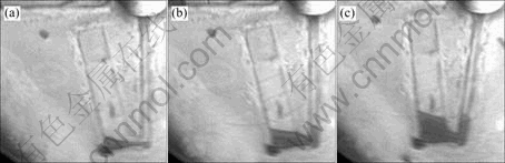
Fig.2 Photographs of bottom gating at different times with rotational speed of 163 r/min: (a) 0.5 s; (b) 1.2 s; (c) 2.0 s
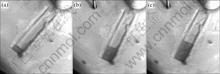
Fig.3 Photographs of top gating at different times with rotational speed of 163 r/min: (a) 0.5 s; (b) 1.2 s; (c) 2.0 s
3.2 Simulation results
The mold applied in simulation is the same as the experimental one that can be used to verify the accuracy of the software. Firstly, use Pore or AutoCAD to build mold and output STL file, then use self-developed software to split the mesh and output SGN file. The mesh spacing is 2 mm, the total number of mesh is 180��47��32=270 720 and the computational grid is shown in Fig.4.
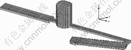
Fig.4 Computational grid
The simulation results in sprue at different rotational speeds are shown in Fig.5 and Fig.6. It is shown that the free surface and the velocity field are changeable with rotary velocity. The free surface is parabola-like, and with increasing the rotary velocity, the free surface radian and the velocity of liquid in sprue increase too.
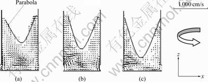
Fig.5 Free surface in sprue at different rotational speeds: (a) 163 r/min; (b) 245 r/min; (c) 375 r/min
The velocity field simulations of bottom filling and top filling at 163 r/min are shown in Fig.7 and Fig.8. Owing to the low rotational velocity, thin wall cavity and big back pressure, it needs more time to fill the cavity. It can be seen from the simulation results that the whole filling process includes two processes: forward filling and back filling. The filling velocity becomes faster and faster in forward filling owing to the increasing centrifugal force. Back filling is a uniform velocity process in which the flow Q equals the cross-sectional area S multiplied by the filling velocity v. The flow of the same time at random position is unchangeable and the cross-sectional area is a constant, so the filling velocity is a fixed value in back filling in cavity.
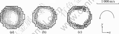
Fig.6 Velocity field of same section in sprue at different rotational speeds: (a) 163 r/min; (b) 245 r/min; (c) 375 r/min
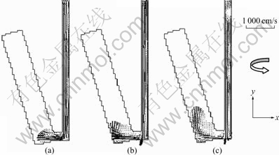
Fig.7 Velocity fields of bottom filling at x-y planes at different times with rotational speed of 163 r/min: (a) 0.5 s; (b) 1.2 s; (c) 2.0 s
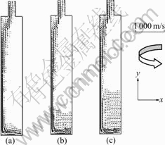
Fig.8 Velocity fields of top filling at x-y planes at different times with rotational speed of 163 r/min: (a) 0.5 s; (b) 1.2 s; (c) 2.0 s
The pressure distribution in centrifugal condition is different from that in gravity condition. In the sprue, the pressure is the largest when ri equals D0/2 and it becomes smaller and smaller with the decrease of rotary radius. When the liquid enters into the runner or cavity, the pressure decreases with increasing filling length. However the pressure increases immediately after the liquid reaches the ingate wall, and the farther from the rotary center, the bigger the pressure, which can be seen from Fig.9 and Fig.10.

Fig.9 Pressure fields in mold at x-z planes at rotational speed of 245 r/min
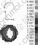
Fig.10 Pressure fields in sprue at x-y planes at rorational speed of 245 r/min
3.3 Discussion
It is hard to study the filling characters of TiAl alloys in vertical centrifugal casting. However the filling process plays an important role in the whole casting process, so hydraulic simulation is explored in this paper to solve the problem. In addition, back pressure should be considered in the experiment that does not employ in the vacuum, which influences the filling state obviously. Depending on the pressure conservation law, the back pressure function for hydraulic simulation is
![]() (7)
(7)
where pA is the pressure of air, which exhausts from coating pore during experiment, pC is the initial pressure inside cavity, VC is the volume of mold cavity, and VA is the volume of remaining void.
In the numerical simulation the pouring time is divided into small time steps and it can be considered that there is a steady state condition within each time step. Therefore, Darcy��s law can be used to calculate the pressure inside the void cavity [18]:
![]() (8)
(8)
where e is the coating thickness, Q0 is the volume of flux passing through the unit of coating area, Kp is the permeability of the coating, �� is the viscosity of the air.
Back pressure will lead to slow the filling rate, which can be solved by increasing the rotary velocity. Fig.2 and Fig.3 show that top filling is faster than bottom filling, and the long runner in bottom filling is the main reason that causes the phenomena. However the bottom filling is better than top filling, which can achieve stable filling. Photos and simulation results (Fig.3 and Fig.8) show that the filling process in centrifugal casting includes forward filling and back filling, and forward filling is an accelerated process, while back filling is a uniform velocity filling process. The cavity filling in bottom gating is more stable than that in top gating, in which the two filling processes both occur in cavity in top filling, resulting in the melts to crash each other seriously. However the melts crash in bottom filling occurs in runner and the cavity filling is a uniform velocity process which can realize the stable filling. Titanium alloys often be produced in vacuum condition and the back pressure has a little effect on the filling process, so bottom gating can realize stable filling and reduce the defects.
The data picked in the experiments and the simulation results are shown in Fig.11 and Fig.12. It can be found that with the increase of filling time, the filling length linearly increase. It can also be seen from Fig.11 and Fig.12 that the simulation results match well with the experiments results.
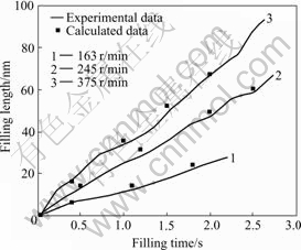
Fig.11 Filling length as function of filling time at different rotational velocities for bottom gating
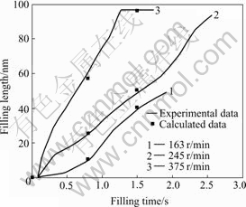
Fig.12 Filling length as function of filling time at different rotational velocities for top gating
The simulation results show that the free surface of melts in sprue during vertical centrifugal casting is parabolic and the radian increases with the rise of rotational speed, which matches with the theoretical analysis of SHENG[19].
The pressure field in centrifugal casting has been analyzed. With increasing the rotational velocity, the pressure increase too. And because of the bigger pressure, the gas in cavity will be driven away and the defects will be reduced as well as the alloy texture will become better.
The experiment results and simulation results show that the filling length will increase with increasing rotary speed in a given range, but over this range, some other cases may occur.
4 Conclusions1) Based on the forces analysis, the mathematical model of liquid filling in vertical centrifugal casting for numerical simulation is obtained. In addition, the comparison between the experimental and the numerical results shows good agreement.
2) Both the numerical simulation results and the experimental results show that the filling length and filling speed increase with the increasing of rotational speed in a given rotary range, and the back pressure plays an important role in filling process under anti- vacuum conditions.
3) Bottom filling is better than top filling, which can realize stable filling.
4) The theoretical analysis and numerical simulation results indicate that the free surface of melts in sprue is parabolic, which is changeable with rotary velocity. Moreover, the pressure in sprue is the largest at wall and smaller at center, when liquid enters into runner or cavity, the pressure decreases gradually, but it increases immediately after the liquid reaches ingate wall.
References
[1] BOYER R R. An overview on the use of titanium in the aerospace industry [J]. Materials Science and Engineering A, 1996, A213: 103-114.
[2] SCHUTZ R W, WATKINS H B. Recent developments in titanium alloy application in the energy industry [J]. Materials Science and Engineering A, 1998, A243: 305-315.
[3] GORYNIN I V. Titanium alloys for marine application [J]. Materials Science and Engineering A, 1999, A263: 112-116.
[4] ZHOU Yan-bang. Titanium Alloy [M]. Beijing: Aviation Industry Press, 2000. (in Chinese).
[5] ZHANG Yan-sheng. The application of titanium and titanium alloy in automotive industry [J]. Progress of Titanium Industry, 2004, 21(1): 16-18. (in Chinese)
[6] SHENG Wen-bin, GUO Jing-jie, SU Yan-qing, DING Hong-sheng, JIA Jun. Forming mechanism of gaseous defect in Ti-48Al-2Cr-2Nb exhaust valves formed with permanent mold centrifugal casting method [J]. Journal of Materials Science and Technology, 2001, 17(5): 569-571.
[7] LI Xi-nian. The technology and application of special shaped casting in vertical centrifugal casing [J]. Special Casting and Nonferrous Alloys, 2000(5): 30-32. (in Chinese)
[8] AUSTIN C M, KELLY T J. Progress in implementation of cast gamma titanium aluminde [J]. Gamma Titanium Aluminides, 1995: 21-32.
[9] LIU K, MA Y C, GAO M, RAO G B, LI Y Y, WEI K, WU X H, LORETTO M H. Single step centrifugal casting TiAl automotive valves [J]. Inermetallics, 2005, 13: 925-928.
[10] SHIMIZU H, HABU T. Mold filling of titanium alloys in two different wedge-shaped molds [J]. Biomaterials, 2002, 23: 2275-2281.
[11] GUO Jing-jie, SHENG Wen-bin, SU Yan-qing, DING Hong-sheng, JIA Jun. Analysis of overflow critical value for TiAl based alloy during the process of centrifugal casting [J]. Trans Nonferrous Met Soc China, 1999, 9(2): 207-212.
[12] WATANABE, WOLDU M, WATANABE K, OKABE T. Effect of casting method on castability of titanium and dental alloys [J]. Journal of Materials Science: Materials in Medicine, 2000, 11: 547-553.
[13] WU M, AUGTHUN M. Numerical simulation of the casting process of titanium tooth crowns and bridges [J]. Journal of Materials Science: Materials in Medicine, 2001, 12: 485-490.
[14] WU M, AUGTHUN M. Numerical simulation of the casting process of titanium removable partial denture frameworks [J]. Journal of Materials Science: Materials in Medicine, 2002, 13: 301-306.
[15] WU M, SAHM P R. Numerical study of porosity in titanium dental castings [J]. Journal of Materials Science: Materials in Medicine, 1999, 10: 519-525.
[16] LI Yuan-dong. Research on influencing factors for filling mould of vertical centrifugal casting [J]. Transactions of Ganshu University of Technology, 1999, 25(1): 22-25. (in Chinese)
[17] GOLDSTEIN R J. Fluid Mechanics Measurements [M]. Washington: Hemisphere, 1983.
[18] MIRBAGHERI S M H, DAVAMI P. Mould Filling Simulation for Casting Process [D]. Tehran, Iran: Sharif University of Technology, 1995.
[19] SHENG Wen-bin. Study on Centrifugal Casting Process of Permanent Mold for TiAl Based Alloy Exhaust Valves [D]. Harbin: Harbin Institute of Technology, 2000.
Foundation item: Project(LHK-04025) supported by the Postdoctoral Startup Fund of Heilongjiang Province, China; Project(50434030) supported by the National Natural Science Foundation of China
Corresponding author: WU Shi-ping; Tel: +86-451-86418816; E-mail: spwu@hit.edu.cn
(Edited by YUAN Sai-qian)
Abstract: A mathematical model of the centrifugal filling process was established. The calculated results show that the centrifugal field has an important influence on the filling process. Moreover, the process of liquid flow and the location of free surface in sprue were simulated based on the Solution Algorithm-Volume of Fraction (SOLA-VOF) technique. In order to verify the mathematical model and computational results, hydraulic simulation experiment was carried out. The results of experiments and numerical simulation indicate the accuracy of mathematical model. Two kinds of filling methods were investigated and the results show that the bottom filling is better than the top filling that can achieve stable filling and reduce defects.
