

Distribution of electric field for carbon nanotube assembly: Experiments (II)
Soongeun KWON 1, Soo-Hyun KIM 1, Kwang-ho KIM 2, Myung-chang KANG 2, Hyung-woo LEE 2
1. Department of Mechanical Engineering, Korea Advanced Institute of Science and Technology (KAIST),
Daejeon 305-701, Korea;
2. National Core Research Center for Hybrid Materials Solution,
Pusan National University, Busan 609-735, Korea
Received 21 April 2010; accepted 10 September 2010
Abstract:
The distribution effect of electric field on the alignment and attachment of carbon nanotubes (CNTs) were investigated. The experimental results were compared with the simulation results according to three different shaped electrodes. In previous simulation, the round shaped electrodes were expected to be more effective for aligning and attaching a single CNT between two electrodes than conical or rectangular shaped electrodes. To verify the simulation results, three different shaped electrodes were introduced and a single multi-walled carbon nanotube (MWNT) was attached. The optimal conditions for aligning and attaching MWNTs such as the frequency, applied voltage and concentration of MWNTs solution were investigated. Through repeated experiments, frequency of 100 kHz-10 MHz, applied voltage of 0.3-1.3 Vrms/��m, concentration of 5 ��g/mL in MWNTs solution were obtained as a possible condition range to attach MWNTs. Under these conditions, the yield of MWNTs attachment between two electrodes was up to 70%. In previous simulation, furthermore, it was verified that the size of the stable or quasi-stable region made CNTs aligned and attached on different shaped electrodes from the comparison of the experimental and simulation results. Most single MWNT attachment was accomplished on the round shaped electrodes.
Key words:
carbon nanotubes; dielectrophoresis; round shaped electrode; simulation;
1 Introduction
Since being discovered in 1991, carbon nanotubes (CNTs) have been studied for many applications in science and engineering fields[1]. This material has attractive properties such as nano size, high aspect ratio and large surface volume as geometrical characteristics. Using CNTs, many nano electronic devices such as memory, logic circuit and sensor have been investigated because CNTs have many superior properties than other materials[2-4]. Aligning and assembling CNTs are very difficult, so many researchers face great obstacles to use CNTs in their devices.
Many methods to align CNTs have been developed. Growth method by chemical vapor deposition (CVD) is very popular to align and assemble CNTs, but it has problems in spacing control between nanotubes, chirality control and optimizing high temperature growth conditions[5-6]. Manual attachment using nano manipulator in SEM is an alternative method to handle an individual carbon nanotube, but there are several disadvantages such as time consuming work and expensive apparatus[7].
In this study, it is suggested that in electric field aligning and assembling CNTs should be on a desired place. To assemble a single CNT, the electrical conditions were optimized and the effect of the shape of electrode was verified in comparison with the simulation result.
2 Background theory and experimental setup
2.1 Dielectrophoresis
In order to align and attach CNTs on a desired place the dielectrophoresis (DEP) was used as a driving force. DEP which causes the translation motion of neutral matter by the polarization effect arised in a nonuniform electric field. A neural particle such as a CNT polarized in an electric field moved to the region with a highest electric field intensity in a nonuniform electric field. Detailed formula and explanation of DEP were mentioned in the simulation paper[8-9].
2.2 Multi-walled nanotubes solution
Fig.1 shows a field emission scanning electron microscope (FESEM) image of multi-walled nanotubes (MWNTs) powder which was obtained from Iljin Nanotech. These MWNTs have a diameter of 15-20 nm and an average length of 10 ��m. In order to drop a droplet of MWNTs solution, a diluted solution of 5 ��g/mL was used in this work. Figs.2(a) and (b) show the MWNTs solution before and after dilution.

Fig.1 FESEM image of MWNTs powder

Fig.2 MWNTs solutions before (a) and after (b) diluting
2.3 Electrode design and apparatus
Fig.3 shows three different shaped electrodes (conical, round and rectangular shaped) made by micro- electro-mechanical system (MEMS) process. The gap distance between two electrodes was 4 ��m. The various electrical conditions such as frequency and the root mean sqnake voltage were applied by the manipulator with micro working resolution, as shown in Fig.4.
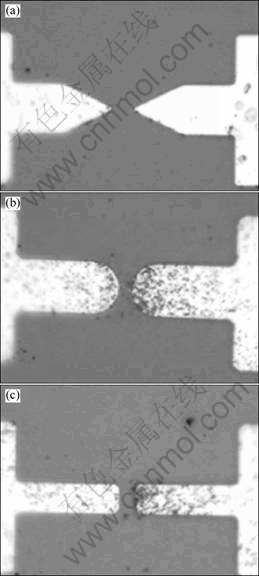
Fig.3 Fabricated electrodes by MEMS process with different shapes: (a) Conical; (b) Round; (c) Rectangular

Fig.4 Probe station having 3-axis manipulator with micro working resolution
3 Results and discussion
3.1 Electrical conditions
Frequency is one of the most important parameters in dielectrophoresis. According to the applied frequency, the dielectrophoretic force is decided as a positive or negative force[8-9]. A positive force attracts the particles and negative force repulses the particles.
In Fig.5, 10 Hz-20 MHz ranged frequency was applied to find the optimal frequency as a positive force. A droplet of MWNTs solution of 1.0-1.5 ��L was dropped and the voltage of 0.8 Vrms/��m was applied. As shown in Fig.5, there were no MWNTs up to 100 Hz.
From 1 kHz, MWNTs were attracted to the electrodes. We can expect that the range of 100 kHz-10 MHz is a possible frequency to align and attract MWNTs.
To obtain an optimal voltage condition, the same quantity of a droplet was dropped and a frequency of 5 MHz was applied. Fig.6 shows the change of the voltage range. Up to 0.1 Vrms/��m, as shown in Fig.6, rare MWNTs were attracted to the electrodes. From the voltage range of 0.3 Vrms/��m, MWNTs were attracted and aligned between electrodes. Over 1.3 Vrms/��m, however, the impurities such as the graphite and surfactants were attracted and attached with MWNTs together. From this result, a proper voltage range to attract MWNTs but no impurities is expected to be 0.3-1.3 Vrms/��m.
3.2 Different shaped electrodes
In order to evaluate the effect of the shape of electrode on aligning and attaching MWNTs, three different shaped electrodes were used in this work. The optimal ranged electrical conditions which have been obtained in the previous experiments have been applied. In this experiment, 0.7 Vrms/��m at 5 MHz was applied between the different shaped electrodes.
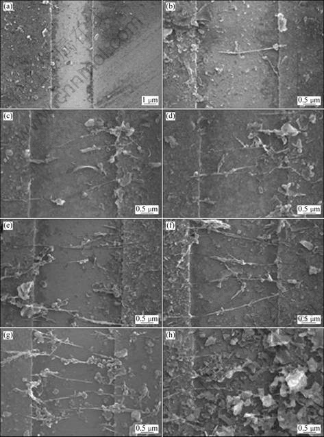
Fig.5 MWNTs alignment and attachment according to frequency of 10 Hz (a), 100 Hz (b), 1 kHz (c), 10 kHz (d), 100 kHz (e), 1 MHz (f), 10 MHz (g) and 20 MHz (h)

Fig.6 MWNTs alignment and attachment according to voltage of 0 Vrms/��m (a), 0.1 Vrms/��m (b), 0.3 Vrms/��m (c), 0.5 Vrms/��m (d), 0.7 Vrms/��m (e), 0.9 Vrms/��m (f), 1.3 Vrms/��m (g) and 1.6 Vrms/��m (h)
Fig.7 shows the experimental results from conical, round and rectangular shaped electrodes. MWNTs were not well attracted to the conical shaped electrodes, as shown in Fig.7(a). In the round shaped electrodes, however, just single MWNTs attachment is obtained with 70% yield. In the case of the rectangular shaped electrodes, several MWNTs were attracted and attached between electrodes (Fig.7(c)).
As mentioned in the previous paper[9], CNTs were expected to stay in the stable or quasi-stable region where the change of the electric field was minimized. From the simulation results, the round shaped electrodes was expected to be more effective shaped electrode with proper sized quasi-stable region. Through these experiments, it was verified that the round shaped electrode was much more effective to attach a single MWNT than conical or rectangular shaped electrode. This result accords with the simulation result considerably.
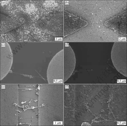
Fig.7 FESEM images of MWNTs aligned and attached on conical (a, b), round (c, d), and rectangular (e, f) shaped electrodes
4 Conclusions
1) The distribution effect of electric field for the alignment and attachment of CNTs was investigated. In addition, the experimental results were compared with the simulation results for three different shaped electrodes.
2) The optimal conditions for aligning and attaching MWNTs such as frequency, applied voltage and concentration of MWNTs solution were investigated.
3) Through repeated experiments, frequency of 100 kHz-10 MHz, applied voltage of 0.3-1.3 Vrms/��m, MWNTs solution concentration of 5 ��g/mL were obtained as a possible range of conditions to attach MWNTs. Under these conditions, the yield of MWNTs attachment between two electrodes was up to 70 %.
4) The round shaped electrode was much more effective to attach a single MWNT than conical or rectangular shaped electrode, which was definitely in accordance with the expectation from the simulation. Most of a single MWNT attachment was accomplished on the round shaped electrodes.
5) In future work, it is needed to expand this control and assembly technique of the nano material into the micro/nano devices.
References
[1] DAI H. Nanotube growth and characterization [J]. Topics Applied Physics, 2001, 80: 29-53.
[2] MCEUEN P L. Single-walled carbon nanotubes electronics [J]. IEEE Transaction on Nanotechnology, 2001, 1(1): 78-85.
[3] BAUGHMAN R H, ZAKHIDOV A A, de HEER W A. Carbon nanotube��The route toward application [J]. Science, 2002, 297(5582): 787-792.
[4] COLLINS P G, AVOURIS P. Nanotube for electronics [J]. Scientific American, 2000: 62-69.
[5] FRANKLIN N R, LI Y. CHEN R J, JAVEY A, DAI H. Patterned growth of single-walled carbon nanotubes on full 4-inch wafers [J]. Applied Physics Letters, 2002, 79(27): 4571-4573.
[6] DELZEIT L, NGUYE C V, STEVENS R M, HAN J, MEYYAPPAN M. Growth of carbon nanotubes by thermal and plasma chemical vapor deposition processes and applications in microscopy [J]. Nanotechnology, 2002, 13(3): 280-284.
[7] YU M F, LOURIE O, DYER M J, MOLONI K, KELLY T F, RUOFF R S. Strength and breaking mechanism of multiwalled carbon nanotubes under tensile load [J]. Science, 2000, 287(5453): 637-640.
[8] POHL H A. Dielectrophoresis: The behavior of neutral matter in nonuniform electric field [M]. Cambridge University Press, 1978: 171-210.
[9] KWON S, KIM S H, KIM K H, KANG M C, LEE H W. The distribution effects of electric field for carbon nanotube assembly: Simulation (I) [J]. Transaction of Nonferrous Metals Society of China, 2011, 21(s1): s117-s120.
(Edited by FANG Jing-hua)
Foundation item: Project supported by Pusan National University Research Grant, Korea; Project(2010-0008-276) supported by NCRC (National Core Research Center) through the National Research Foundation of Korea funded by the Ministry of Education, Science and Technology
Corresponding author: Hyung-Woo LEE; Tel: +82-51-5103160; E-mail: LHW2010@pusan.ac.kr; Myung-Chang KANG; Tel: +82-51-510-2361; E-mail: kangmc@pusan.ac.kr
