
J. Cent. South Univ. (2012) 19: 2115-2124
DOI: 10.1007/s11771-012-1253-5![]()
Stress distributions on crown-luting cement-substrate system with finite element method
S. SEN1, M. S. GULER1, C. GULER2
1. Department of Mechanical Engineering, Ataturk University, Erzurum 25240, Turkey;
2. Department of Pediatric Dentistry, Inonu University, Faculty of Dentistry, Malatya 44280, Turkey
? Central South University Press and Springer-Verlag Berlin Heidelberg 2012
Abstract:
The aim of this work is to analyze the stress distributions on a crown-luting cement-substrate system with a finite-element method in order to predict the likelihood of interfacial micro cracks, radial or circumferential cracks, delamination, fracture and delamination with torsion. The contact and layer interface stresses in elastic layered half-space indented by an elastic sphere were examined using finite element method. The model consists of crown, luting cement and substrate. The solutions were carried out for three different elastic moduli of luting cement. It was placed between the cement and the substrate as a middle layer and its elastic module was chosen lower than the elastic module of crown and higher than the elastic module of dentin. An axisymmetric finite element mesh was set up for the stress analysis. Stress distributions on the contact surface and the interfaces of crown-luting cement and luting cement-dentin have been investigated for three different values of luting cement by using ANSYS. The effects of the luting cement which has three different elastic moduli on the pressure distribution and the location of interfacial stresses of the multi-layer model have been examined. The mechanism of crack initiation in the interfaces and interfacial delamination was also studied quantitatively. For each luting cement, the pressure distribution is similar at the contact zone. Stress discontinuities occur at the perfect bonding interfaces of the crown-luting cement and the substrate-luting cement. The maximum stress jumps are obtained for the highest and the lowest elastic module of the luting cement. In the crown-luting cement-substrate system, failures may initiate at crown-luting cement region for luting cement with the lowest elastic module value. In addition, failures at luting cement-substrate region may occur for luting cement with the highest elastic module. In the luting cement, the medium elastic module value is more suitable for stress distribution in crown-luting cement-substrate interfaces.
Key words:
1 Introduction
Generally, layered material systems are either hard or stiff layers on a soft/compliant substrate, or soft/compliant layers on a hard substrate. The problem has technological importance because such crown-luting cement-substrate systems, i.e. typically a ceramic crown-different luting cements-dentin substrate, are being used widely to treat the patients, including other engineering and dentistry materials. It is well-known that the useful layer life depends on either detachment of the coating, adhesive failure, or fracture of the layer, cohesive failure, rather than conventional wear [1]. Cohesive failure results from stresses within the layers and at the surface, while adhesive failure occurs due to interface stresses. When designing such contacting layered material system, it is important to have comprehensive knowledge about the nature and the origin of these stresses for minimizing the strain fields of layered materials. Furthermore, the magnitude and distribution of the interfacial stresses, the mechanical reliability and the analysis of contact failures are also necessary to be assessed.
There are a series of works related with analytical and numerical solutions in this area. KRAL et al [2] studied the repeated indentation of a half-space with a rigid sphere, performing up to four complete loads and unload cycles on half-space possessing different elastic and plastic properties. It was found that the surface stresses depended primarily on the strain-hardening parameters and only secondarily on the elastic properties, and that re-yielding occurred upon unloading in a small surface region near the edge of contact at the contact at maximum load. KRAL et al [3-4] presented a finite-element analysis of repeated indentation of an elastic-plastic layered medium with a rigid sphere for surface [3] and subsurface [4]. Their model had a perfectly adhering layer with using two different thicknesses, and elastic module and yield stress are two and four times greater than those of the substrate. They showed that the tensile radial and hoop stresses are critical to the susceptibility of the layer surface to ring and radial cracking. In their work, it was illustrated that the surface stresses showed very slight changes with subsequent load cycles for the non-hardening materials and virtually no change for the hardening materials. It was also shown that the stresses at the layer/substrate and on the axis of symmetry showed only slight changes with subsequent load cycles for the non-hardening materials and virtually no change for the hardening materials.
Finite-element analyses for multi-layer contact under axisymmetric loading have been performed by TANGENA and WIJINHOVEN [5]. They investigated the correlation between mechanical stresses and wear in a layered system. TIAN and SAKA [6] analyzed the contact problem of a rigid cylinder indenting an elastic-plastic two-layer half-space used in electrical contacts using finite-element analysis. They quantitatively addressed the mechanism of crack initiation at the interfaces and interfacial delamination.
de JAGER et al [7] explained that knowledge of factors, which influences stress and its distribution, is the key importance for the successful production of durable all-ceramic restorations. They concluded that a non-uniform cement layer might result in stresses exceeding the bond strength.
LI et al [8] analyzed the stress distribution in weakened roots restored with different cements in combination with titanium alloy posts using finite element analysis. They demonstrated that elastic module was indeed one of the important parameters to evaluate property of the cements. In addition, they also found that the cement with elastic module similar to that of dentin could reinforce weakened root and reduced the stress in dentin.
REKOW et al [9] investigated the relative contribution of variables in the crown-cement-tooth system that can influence magnitude of maximum principal stress in all-ceramic crowns. They found that crown material and thickness had the primary importance in stress magnitude but other variables (cement module, load position, and supporting tooth core) also contributed to the stress magnitude. Interactions between these variables can have an important influence, particularly, the stress in the crown is not necessarily sensitive to the same factors for all crown material systems.
OZEL et al [10] applied the adhesively bonded single lap joint (SLJ) in bending load using nonlinear finite element analysis. They showed that adherent thickness played an important part in the joint performance, while the stiff adhesive gave stronger joint strength when using thick adherents; the opposite was the case for the flexible adhesive when using thin adherents. They concluded that these results were related to the mechanical behaviors of the used adhesives.
SEN et al [11-12] investigated that an elastic- plastic contact problem in elastic-work hardening layered half-space indented and removed with a rigid sphere is solved numerically by using the finite element method. They found that the stresses and strains were obtained depending on the ratio of the film thickness to the substrate thickness.
FAULKNER et al [13] assessed the influence of a deformable indenter by comparing the finite element results for a deformable indenter with those of a rigid indenter. They found that when the indenter was assumed to be rigid, the contact pressures in the elastic regime were higher than those given by the deformable indenters. However, as deformation proceeded and plasticity became dominant, the differences between the three sets of results reduced. The rigid indenter results were also shown to give the lowest peak radial tensile stress which was responsible for cracking of the film normal to the surface. Finally, comparison of the von Mises stress contours revealed that varying indenter properties affected the point at which yielding commenced. The results showed that the rigid indenter caused the coating and substrate to yield prematurely at a lower load than the deformable indenters.
TANG et al [14] investigated the normal indentation problem of a deformable indenter in contact with a strain hardening substrate coated with an elastic-perfectly plastic layer using the finite element method. The comparison showed that, when the indenter was assumed to be rigid, the contact pressures were significantly higher than those for the deformable indenter during elastic deformation. When plasticity was more pronounced, the peak pressures just inside the contact edge were also higher for the rigid indenter. Similarly, the results assuming a rigid indenter gave a lower value of maximum radial tensile stress along the coating surface when compared with those using a deformable indenter, which was responsible for the cracking of the film. In order to examine the effects of strain hardening, the above solutions were compared with a system having an elastic-perfectly plastic substrate. Comparison between the two sets of results showed that the strain hardening medium developed a smaller contact area and higher central and peak contact pressures inside the contact edge during plastic deformation. It was also shown that the use of a strain hardening substrate alleviated the maximum radial tensile stress just outside the contact edge.
In this work, the contact, layer interface and side stresses caused by indenting a brittle and thin elastic layer with high elastic module on luting cement have been examined. An axisymmetric finite element mesh was set up for the stress analysis. The contact stress arising on the free surface, within the crown and the luting cement at both sides of the crown layer-luting cement layer and the luting cement layer-substrate layer (dentin) interfaces were examined by using ANSYS. The effects of the luting cement which has three different elastic modulus values on the pressure distribution and the location of interfacial stresses of the multi-layer have been examined. The mechanism of crack initiation on the interfaces and interfacial delamination was also studied quantitatively.
2 Materials and methods
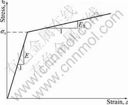
A rigid sphere indenting an elastic layer on luting cement on which the elastic-plastic work-hardening substrate for an axisymmetric half-space under normal contact was considered is modeled using a finite- element model. The boundary conditions and mesh are given in Fig. 1, and the boundary conditions may be expressed as follows:
��y(r,0)=0, |r|>a (1)
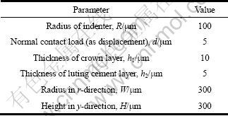
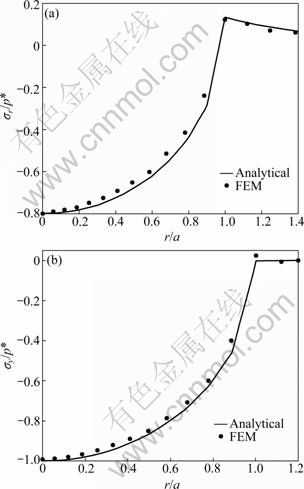
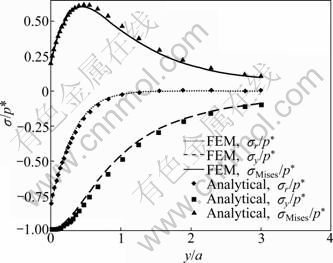
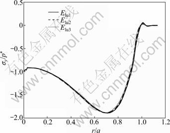
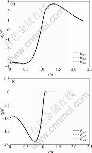
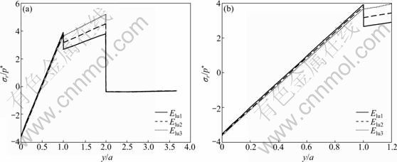
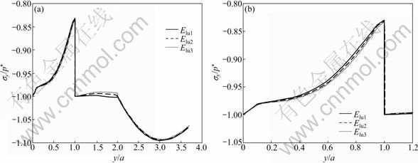
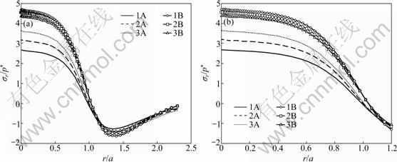
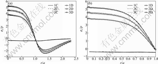
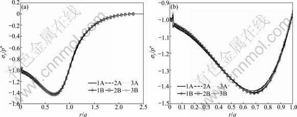
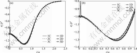
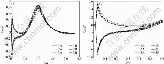
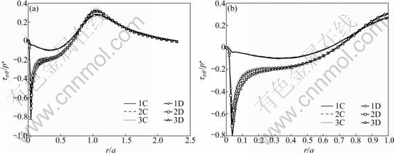
��r?(r,0)=0, -�� where a is the radius of the contact area. Perfect bonding is assumed at the interfaces between crown-luting cement and luting cement-substrate, i.e. displacements across the interfaces are continuous: u(1)(r, h1)=u(2)(r, h1) (3) u(2)(r, h1+h2)=u(3)(r, h1+h2) (4) v(1)(r, h1)=v(2)(r, h1) (5) v(2)(r, h1+h2)=v(3)(r, h1+h2) (6) u=v=0 (r, y����) (7) where the superscripts ��1��, ��2�� and ��3�� represent the crown layer, luting cement layer and substrate, respectively; h1 and h2 are the layer thicknesses of the crown and the luting cement, respectively. The materials for the layer and the substrate are assumed to possess linearly elastic and bilinearly elastic-plastic behavior, respectively, and the material curve of the substrate is given in Fig. 2. All the material properties are listed in Tables 1 and 2. Elastic modulus (E) for the substrate is chosen as 220 GPa, similar to that for dentin, and the luting cement layer moduli vary among 1.25, 1.50 and 1.75 times that of the substrate. The range of 275- 385 GPa covers the moduli of luting cements which are likely to be of interest for tribological application. The moduli of luting cements were symbolized as Elu1, Elu2 and Elu3 for 275, 330 and 385 GPa, respectively (Table 1). In all cases, the penetration of spherical indenter with a radius of 100 ��m was modeled, providing three different elastic moduli of the luting cement. Fig. 1 Finite-element model and boundary conditions (a) and solution mesh (b) Fig. 2 Bilinearly elastic-plastic behavior of substrate material (ET=��E) 3 Finite element model To conduct the finite-element analysis for the indentation of a spherical indenter on the layered half- space, the axisymmetric dimensions in the half-space are modeled using the axes of r and y, respectively. Figure 1(a) shows the finite-element model and the boundary conditions. Because of the symmetry and the axisymmetric geometry, only half of the layered media is considered. The mid-plane (OA) is restricted to move only along the y-direction. The displacement at the bottom plane of the block (AB) is far away from the contact area and is assumed to be zero in the vertical and horizontal directions. Figure 1(b) shows the whole finite-element mesh. The whole mesh contains an arrangement of 11 400 quadrilaterals and four nodes axisymmetric isoparametric elements, and the total number nodes are 11 819. A total of 2 400 elements are in the layered media system, and the remainder is in the substrate. The horizontal and vertical dimensions of the model are both 300 ��m, which are large enough to allow the stresses and the displacements to be insignificant at the boundaries. The interfaces between the multi-layer and the substrate were assumed to be perfectly bonded, i.e. the displacements at the interface were continuous (Eqs. (3) and (4)). The interface constraints were satisfied with using common nodes which belong to the elements on both sides. The normal contact between the rigid sphere and layered half-space was modeled as the three-noded axisymmetric interface (gap) elements. The initial nodal gaps between the rigid sphere and the surface of the layered half-space were prescribed by the circumference of the rigid sphere. The ANSYS finite-element software detects the gap changes and indicates the gap closure in the y-direction. Whenever the closure distance becomes zero at any node, the contact is assumed to occur and an external reaction force is exerted on that node, otherwise no force is transferred. The parameter associated with the interface elements, the ��friction coefficient��, is assumed to be zero. Table 1 Mechanical properties of materials Table 2 Load and geometrical parameters used in stress analysis To verify the boundary conditions and the finite- element mesh for an axisymmetric solid material, firstly, the finite element results for an uncoated substrate model were compared with the analytical solutions of the Hertzian stresses field. The difference between the computed results and the corresponding analytical solutions were found to be negligible and the comparisons of the results of those two solutions are given in Figs. 3 and 4. It can be seen from Fig. 3(a) that ��r at the edge of the contacts is tensile, which for the uncoated substrate has a maximum value of 0.13p* (p* is the center pressure, p*=-��y) and for a Poisson ratio of 0.30. Analytical and finite-element solutions of the elastic ratio of ��y/p* on the contact surface (r/a=0) is given in Fig. 3(b). From the comparison of these results, it can be seen that there is fairly good agreement between the solutions. Figure 4 indicates that the nonzero stress components ��r, ��y, ���� and von Mises equivalent stresses obtained from the finite-element analysis are also in reasonably good agreement with those predicted by the analytical method [15]. In addition, as shown in Fig. 4, the agreement appears to be reasonably good for the stress distributions in the vertical direction beneath the surface. Fig. 3 Normalized ��r (a) and ��y (b) at contact surface of single material (y/a=0) Fig. 4 Normalized stress distribution along axes of symmetry of single material (r/a=0) The results of the present model were compared with those of Refs. [11,13-14], and very close results were observed. According to this comparison, at the first contact point O in Fig. 1(a), the ratio of the maximum ��y of ELASTICA to the maximum ��y of the present work was calculated as 0.964 5 in elastic solution, and the ratio of ��r (=����) was obtained as 1.026. The material properties of the layer were taken as the same with the properties of the substrate. It may be concluded, therefore, that the finite- element mesh used in this work is an acceptable representation of an elastic semi-infinite solid. 4 Results and discussion In the elastic stress analysis of the homogeneous media, the stresses are usually normalized by the maximum Hertzian pressure of the contact, and here all the calculated stresses have been presented in a normalized form. In this work, the stresses were normalized with respect to the corresponding center pressure p*(=-��y ) on the appropriateness, where positive values indicate tensile stresses while negative values denote compressive stresses. The solutions presented here assume that plastic deformation occurs in the substrate and the layers deform elastically. The radius of a rigid sphere R is 100 ��m, which is much larger than the expected contact radius a, and the constant indentation depth is, d=5 ��m. The first contact point ��O�� between the indenter and the crown-luting cement-substrate media is shown in Fig. 1. In Figs. 5-9, the elastic moduli of these luting cements are 275, 330 and 385 GPa for luting cement 1, 2 and 3 in Table 1, respectively. In addition, in Figs. 8 and 9, symbol A and B indicate the stresses at the sides of luting cement and crown in the crown-luting cement interface line, while symbol C and D in Fig. 10 indicate stresses at the sides of substrate and luting cement in the luting cement-substrate interface line, respectively. Fig. 5 Normalized ��y distribution (��y/p*) at contact zone between indenter and substrate Fig. 6 Normalized stress distribution at contact zone between indenter and the substrate: (a) ��r/p*; (b) ����/p* Fig. 7 Normalized ��r distribution along axis of symmetry: (a) For y/a=0-3.5; (b) For y/a=0-1.2 Fig. 8 Normalized ��y distribution along axis of symmetry: (a) For y/a=0-3.5; (b) For y/a=0-1.2 Fig. 9 Normalized ��r distribution along crown-luting cement interface (Symbols 1, 2 and 3 for Elu1, Elu2 and Elu3, and symbols A and B for luting cement side and crown side along crown-luting cement interface, respectively): (a) For r/a=0-2.5; (b) For r/a=0-1.2 4.1 Pressure distribution and stress at contact surface In contact stress analysis, obtaining an accurate pressure distribution is necessarily the first step in determining the subsurface stress. A parabolic pressure distribution (Hertzian distribution) is produced when a homogeneous elastic half-space is indented by an elastic or rigid sphere. The contact pressure distribution, p, and the radius of the contact zone, a, are also given in Ref. [16]. In the present work, an elastic layer and a bilinear elastic-plastic substrate are indented by a rigid sphere, and the contact pressure distribution is expected to be more complicated. The pressure, p (=-��y), is normalized by the center pressure, p*, and the distance from the contact center r is normalized by the corresponding contact radius, a. Figure 5 shows the normalized contact stress distribution ratio of ��y /p* for the considered luting cement with three different elastic moduli. From Fig. 5, it is seen that the normalized contact stress distributions, ��y/p*, have similar trends for luting cement with three different elastic moduli. The contact stress ��y is compressive for r/a<1 and becomes nearly zero at about r/a=1. As seen in Fig. 5, ��y is compressive at the contact zone, and first it increases gradually, after that it reduces down quickly and finally goes to zero at the edge of the contact as expected. Thus, it can be concluded that ��y /p* is not influenced by the elastic module. In Fig. 6(a), it has been shown that the radial stress, ��r, is compressive in the contact zone, and then becomes tensile at the edge and outside contact. As given in Fig. 6(b), ���� is compressive at the contact zone, and first it increases gradually, after that it reduces down quickly and finally goes to zero at the edge of the contact. It can be seen from Fig. 6(a) that ��r increases up to a ratio of about r/a=1.4, then reduces gradually for higher values of r/a. It can be seen from Fig. 6(b) that ���� increases up to a ratio of about r/a=1.1, then remains constant for higher values of r/a. The stress locations of practical interest are those at the surface of the layered substrate and at the crown-luting cement-substrate interfaces. The stress components relevant to the analysis are ��r and ����, which can cause brittle failure of the film at its surface and interface [1] or layer detachment. High compressive in-plane stresses can cause buckling of the film in the presence of interfacial cracks and local areas of poor adhesion, and in-plane shear stresses ��r�� can contribute to either shear or mixed mode failures. In the system under cyclic loading, the crown-luting cement-substrate interface failure or interfacial delamination can be caused by plastic deformation if the bonding forces along the interface between the crown-luting cement-substrate are not high enough. 4.2 Stresses along loading axis The stresses along the loading axis (y-direction) are presented in Figs. 7 and 8 for luting cements with three different elastic moduli. The shear stresses ��r�� are zero along the loading axis because of the loading symmetry. Thus, the stresses, ��r, ��y and ���� are the principal stresses along the loading axis. The vertical distance y below the contact is normalized by the radius of the contact, and the stresses are normalized by the center contact pressure p*. The test run of the elastic analysis of a homogeneous elastic half-space indented by a rigid sphere shows that ��r is equal to ���� along the loading axis. It is well known that in the axisymmetric contact of solids, maximum value of |��y-��r|, for ��=0.3, is 0.62p* at a depth of 0.48a, and according to the Mises criterion, ��Mises=0.625p* for uncoated elastic-plastic material [6]. The current result for ��r is obtained as compressive at y/a=0-0.5 and then as tensile at y/a= 0.5-1.0 (Fig. 7). The results for stresses in luting cement layer, ��r, are obtained as tensile. The results are similar for the different elastic moduli of luting cement. The results for stress in substrate (dentin) layer, ��r, are obtained as compressive and near zero. The differences for values between crown-luting cement layer and luting cement layer-substrate (dentin) are discontinuous across the interface, because of different elastic moduli and displacement continuity constant at the interface. Thus, all these discontinuities in Fig. 7 indicate the location of the interface. As a result, the risk of delamination increases in luting cement-substrate (dentin) layer interface of luting cement with higher elastic module, but the risk of delamination reduces in crown-luting cement layer of luting cement with higher elastic module. The result of present work for stress, ��y, is obtained as compressive for all layers. All results are similar for luting cement with different elastic modulus values (Fig. 8). The risk of subsidence increases in crown-luting cement layer for different elastic moduli. Thus, this layer may have hoop cracks. In addition, Fig. 8 shows that magnitudes of the stress ��y on the contact surface (y/a=0) are higher than those of the normal stress. 4.3 Stresses at interface 4.3.1 Stresses in crown-luting cement interface line The magnitude and the distribution of subsurface stresses along the interface line have great importance in layered media. Adhesive forces on the crown-luting cement-substrate interfaces should resist tensile or shear stresses for the luting cement layer to remain bonded to the substrate and the crown. The shear stresses are normalized by the ��y in order to present the effect of discontinuity at the interface, and the variations of stresses are given by two lines for all the values of three different elastic moduli of luting cement. Each of the lines shows the stress in the layer near the interfaces and the other is in the substrate near the interface. As the axial stress ��y and the radial stress ��r�� in-plane must be the same, the radial and Hoop stresses ��r and ���� would be discontinuous across the interface. These properties are clearly seen in Fig. 9 and Fig. 10 for ��r, Fig. 11 and Fig. 12 for ��y, Fig. 13 and Fig. 14 for ��r��. The radial stress, ��r, is tensile below the contact zone (r/a=0) and becomes compressive at about r/a>1 (Fig. 9), and the magnitude of ��r, is nearly the same for both the crown and luting cement. This result is similar for three different elastic modulus values of luting cement. Luting cement with the highest elastic module is suitable for the radial stress. However, in the crown- luting cement interface radial or circumferential, cracks and delamination may be seen due to different radial stresses. Fig. 10 Normalized ��r distribution along luting cement-substrate interface (Symbols 1, 2 and 3 for Elu1, Elu2 and Elu3, and symbols C and D for substrate side and luting cement side along luting cement-substrate interface, respectively): (a) For r/a=0-2.0; (b) For r/a= 0-1.0 Fig. 11 Normalized ��y distribution along crown-luting cement interface (Symbols 1, 2 and 3 for Elu1, Elu2 and Elu3, and symbols A and B for luting cement side and crown side along crown-luting cement interface, respectively): (a) For r/a=0-2.5; (b) For r/a=0-10 Fig. 12 Normalized ��y distribution along luting cement-substrate interface (Symbols 1, 2 and 3 for Elu1, Elu2 and Elu3, and symbols C and D for substrate side and luting cement side along luting cement-substrate interface, respectively): (a) For r/a=0-2.3; (b) For r/a= 0-1.0 Fig. 13 Normalized ��r�� distribution along crown-luting cement interface (Symbols 1, 2 and 3 for Elu1, Elu2 and Elu3, and symbols A and B for luting cement side and crown side along crown-luting cement interface, respectively): (a) For r/a=0-2.5; (b) For r/a=0-0.6 Fig. 14 Normalized ��r�� distribution along luting cement-substrate interface (Symbols 1, 2 and 3 for Elu1, Elu2 and Elu3, and symbols C and D for substrate side and luting cement side along luting cement-substrate interface, respectively): (a) For r/a=0-2.30; (b) For r/a =0-1.0 Stresses ��y in crown-luting cement interface line are seen compressive for three different elastic modulus values of luting cement. The magnitudes of stresses are higher than the stresses in contact zone (Fig. 11). ��y becomes zero at r/a=2.3. Thus, in crown-luting cement interface line (r/a=0-2.3), subsidence may be seen. In addition, circumferential crack and delamination may be seen. Shear stresses, ��r��, for the side of the luting cement at the interface (r/a=0-0.2) are tensile, and become compressive with increasing values of r/a (Fig. 13). Shear stresses, ��r��, for the side of the crown at the interface (r/a=0-0.55) are compressive, and become zero at r/a=0.55, then become tensile with increasing values of r/a by parabolic (Fig. 13). Thus, at r/a=0.5 and r/a=1.8, cracks and fracture may be seen because of different signs of the stresses. Specially, at r/a=0-0.5, delamination with torsion may be seen. 4.3.2 Stresses in luting cement-substrate interface line The radial stresses, ��r, for the side of the luting cement at the interface are in tensile characteristics at the bottom of the contact zone, and become compressive after r/a=1. This result is similar for three different elastic modulus values of luting cement (Fig. 10). The radial stresses, ��r, for the side of the substrate at the interface are compressive and stationary values do not change significantly (Fig. 10). Below the contact zone, the stresses are different sign values between the side of the luting cement and the side of the substrate. As a result, circumferential cracks and delamination may be seen in this region. The stresses in the luting cement-substrate interface line, ��y, are similar with stresses in crown-luting cement interface line (Fig. 12). All of the shear stresses, ��r��, for the side of the luting cement and substrate at the interface are compressive (r/a=0-0.7), and become tensile after r/a=0.7 (Fig. 14). As a result, delamination with torsion may be seen in this region (Fig. 14). 4.4 Failure of layered media In the present finite-element analysis, it is assumed that at the sharp interfaces of three dissimilar materials, crown-luting cement and substrate are perfectly bonded together. But in reality this assumption is unlikely to be the case since residual stresses, porosity and other micro structural defects may develop in the layer and/or at the interface during the process. In the literature, there are a few criteria for initiation of interfacial cracks. These criteria may be grouped into three types: the energy criterion, the local strain criterion and local stress criterion. According to all these criteria, it is necessary that material compatibility should be considered in designing system and the tensile and shear stresses are kept as small as possible. As shown in Figs. 7-14, an interfacial micro crack, radial or circumferential cracks, delamination, fracture and delamination with torsion may initiate. The bonding strength of the interfaces exceeds the maximum shear stresses at the interface. 5 Conclusions 1) For each luting cement, the pressure distribution is found similar at the contact zone. 2) Stress discontinuities occur at the interfaces since perfect bonding along the crown-luting cement-substrate interfaces is assumed and the maximum stress jumps are obtained for the highest and the lowest elastic modulus value. Thus, we consider that luting cement with medium elastic module value is more suitable. 3) In the crown-luting cement-substrate system, failures might initiate at crown-luting cement region for luting cement with the lowest elastic modulus value. In addition, failures occur at luting cement-substrate region for luting cement with the highest elastic modulus value. References [1] ARNELL R D. The mechanism underlying the cracking and spalling of thin hard coating [C]// Ion and Plasma Assisted Techniques. Geneva, 1989: 226-231. [2] KRAL E R, KOMVOPOULOS K, BOGY D B. Elastic-plastic finite element analysis of repeated indentation of a half-space by a rigid sphere [J]. Journal of Applied Mechanics, ASME Transactions, 1993, 60: 829-841. [3] KRAL E R, KOMVOPOULOS K, BOGY D B. Finite element analysis of repeated indentation of an elastic-plastic layered medium by a rigid sphere. Part 1: Surface result [J]. Journal of Applied Mechanics, ASME Transactions, 1995, 62: 20-28. [4] KRAL E R, KOMVOPOULOS K, BOGY D B. Finite element analysis of repeated indentation of an elastic-plastic layered medium by a rigid sphere. Part 2: Subsurface results [J]. Journal of Applied Mechanics, ASME Transactions, 1995, 62: 29-42. [5] TANGENA A G, WIJNHOVEN P J M. The correlation between mechanical stresses and wear in a layered system [J]. Wear, 1988, 121: 27-35. [6] TIAN H, SAKA N. Finite element analysis of an elastic-plastic two-layer half-space: Normal contact [J]. Wear, 1991, 148: 47. [7] de JAGER N, PALLAV P, FEILZER A J. The influence of design parameters on the FEA-determined stress distribution in CAD-CAM produced all-ceramic dental crowns [J]. Dent Mater, 2005, 21(3): 242-251. [8] LI L L, WANG Z Y, BAI Z C, MAO Y, GAO B, XIN H T, ZHOU B, ZHANG Y, LIU B. Three-dimensional finite element analysis of weakened roots restored with different cements in combination with titanium alloy posts [J]. Chinese Medical Journal, 2006, 119(4): 305-311. [9] REKOW E D, HARSONO M, JANAL M, THOMPSON V P, ZHANG G. Factorial analysis of variables influencing stress in all-ceramic crowns [J]. Dent Mater, 2006, 22(2): 125-132. [10] OZEL A, KADIOGLU F, SEN S, SADELER R. Finite element analysis of adhesive joints in four-point bending load [J]. The Journal of Adhesion, 2003, 79: 683-697. [11] SEN S, AKSAKAL B, OZEL A. A finite-element analysis of the indentation of an elastic-work hardening layered half-space by an elastic sphere [J]. Int J Mech Sci, 1998, 40(12): 1281-1293. [12] SEN S, GUN B. A finite-element analysis of residual stress at the unloaded stage of the indentation of an elastic-work hardening layered half-space by a rigid sphere [J]. Surface & Coatings Technology, 2006, 200: 2841-2851. [13] FAULKNER A, TANG K C, SEN S, ARNELL R D. Finite element solutions comparing the normal contact of an elastic-plastic layered medium under loading by (a) a rigid and (b) a deformable indenter [J]. The Journal of Strain Analysis for Engineering Design, 1998, 33(6): 411-418. [14] TANG K C, FAULKNER A, SEN S, ARNELL R D. The finite element analysis of a strain hardening layered medium under normal loading by (a) a rigid and (b) a deformable indenter [J]. The Journal of Strain Analysis for Engineering Design, 1998, 33(6): 401-410. [15] JOHNSON K L. Contact mechanics [M]. Cambridge: Cambridge University Press, 1985: 62. [16] JOHNSON K L. Contact Mechanics [M]. Cambridge: Cambridge University Press, 1985: 155-184. (Edited by HE Yun-bin) Received date: 2011-08-08; Accepted date: 2011-12-26 Corresponding author: S. SEN, Professor; Tel: +90-442-2314852; Fax: +90-442-2360957; E-mail: sadrisen@yahoo.com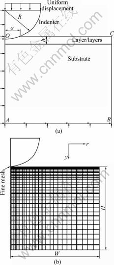

Abstract: The aim of this work is to analyze the stress distributions on a crown-luting cement-substrate system with a finite-element method in order to predict the likelihood of interfacial micro cracks, radial or circumferential cracks, delamination, fracture and delamination with torsion. The contact and layer interface stresses in elastic layered half-space indented by an elastic sphere were examined using finite element method. The model consists of crown, luting cement and substrate. The solutions were carried out for three different elastic moduli of luting cement. It was placed between the cement and the substrate as a middle layer and its elastic module was chosen lower than the elastic module of crown and higher than the elastic module of dentin. An axisymmetric finite element mesh was set up for the stress analysis. Stress distributions on the contact surface and the interfaces of crown-luting cement and luting cement-dentin have been investigated for three different values of luting cement by using ANSYS. The effects of the luting cement which has three different elastic moduli on the pressure distribution and the location of interfacial stresses of the multi-layer model have been examined. The mechanism of crack initiation in the interfaces and interfacial delamination was also studied quantitatively. For each luting cement, the pressure distribution is similar at the contact zone. Stress discontinuities occur at the perfect bonding interfaces of the crown-luting cement and the substrate-luting cement. The maximum stress jumps are obtained for the highest and the lowest elastic module of the luting cement. In the crown-luting cement-substrate system, failures may initiate at crown-luting cement region for luting cement with the lowest elastic module value. In addition, failures at luting cement-substrate region may occur for luting cement with the highest elastic module. In the luting cement, the medium elastic module value is more suitable for stress distribution in crown-luting cement-substrate interfaces.
