

J. Cent. South Univ. (2018) 25: 2512-2522
DOI: https://doi.org/10.1007/s11771-018-3932-3

Theoretical and numerical study on reinforcing effect of rock-bolt through composite soft rock-mass
ZHAO Zeng-hui(������)1, 2, GAO Xiao-jie(������)1, 2, TAN Yun-liang(̷����)1, 2, MA Qing(����)1, 2
1. State Key Laboratory of Mining Disaster Prevention and Control Co-founded by Shandong Province and
the Ministry of Science and Technology, Shandong University of Science and Technology,Qingdao 266590, China;
2. College of Mining and Safety Engineering, Shandong University of Science and Technology,Qingdao 266590, China
 Central South University Press and Springer-Verlag GmbH Germany, part of Springer Nature 2018
Abstract:
Anchoring mechanism and failure characteristics of composite soft rock with weak interface usually exhibit remarkable difference from those in single rock mass. In order to fully understand the reinforcement mechanism of composite soft roof in western mining area of China, a mechanical model of composite soft rock with weak interface and rock bolt which considering the transverse shear sliding between different rock layers was established firstly. The anchoring effect was quantified by a factor defined as anchoring effect coefficient and its evolution equation was further deduced based on the deformation relationship and homogenized distribution assumption of stress acting on composite structure. Meanwhile, the numerical simulation model of composite soft rock with shear joint was prompted by finite element method. Then detailed analysis were carried out for the deformation features, stress distribution and failure behavior of rock mass and rock bolt near the joint under transverse load. The theoretical result indicates that the anchoring effect of rock-bolt through weak joint changes with the working status of rock mass and closely relates with the physical and geometric parameters of rock mass and rock bolt. From the numerical results, the bending deformation of rock bolt accurately characterized by Doseresp model is mainly concentrated between two plastic hinges near the shear joint. The maximum tensile and compression stresses distribute in the plastic hinge. However, the maximum shear stress appears at the positions of joint surface. The failure zones of composite rock are produced firstly at the joint surface due to the reaction of rock bolt. The above results laid a theoretical and computational foundation for further study of anchorage failure in composite soft rock.
Key words:
composite soft rock; anchorage; evolution equation; numerical model; plastic hinge��
Cite this article as:
ZHAO Zeng-hui, GAO Xiao-jie, TAN Yun-liang, MA Qing. Theoretical and numerical study on reinforcing effect of rock-bolt through composite soft rock-mass [J]. Journal of Central South University, 2018, 25(10): 2512�C2522.
DOI:https://dx.doi.org/https://doi.org/10.1007/s11771-018-3932-31 Introduction
Mine engineering in western area of China is mainly located in composite weakly cemented soft rock which exhibits typical characteristics of low strength, instability, and weak cohesion between different rock layers [1]. As a passive support, the anchoring force of non-prestressed full bonded rock bolt changes with the deformation of surrounding rock. Significant vertical displacement will be induced in the composite soft roof after tunnel excavation. Besides, shear sliding between different rock layers in the horizontal direction simultaneously appears due to the bending and sinking of roof as well as the horizontal stress. This makes the bolt bear not only axial force, but also shear force and bending moment which will cause shear failure in addition to the axial damage. Special rock lithology and structural feature result in more complex anchoring mechanism in composite soft rock.
Studies on the anchoring effect of rock bolt currently are mainly focused on a single rock medium. Two aspects were paid special attentions: one is the load transfer mechanism, the other is the reinforcement effect [2, 3]. Many scholars have made some results using a variety of methods and means. PHILLIPS [4], MA et al [5], and REN et al [6] constructed respectively the distribution function of shear stress along the length of anchorage body by theories of mechanics. In order to consider the elastoplastic behavior of rock medium, XIAO et al [7], HE et al [8] and MUYA et al [9] discussed the anchoring mechanism by establishing a series of elastoplastic constitutive models for different anchorage media. GOEL et al [10] and LIU et al [11] then analyzed the mechanical effect and influence factors of anchorage through numerical simulation. In the experimental aspect, KILIC et al [12, 13] and BENMOKRANE et al [14, 15] studied the influence of bolt shapes and cohesion differences of grout on the bearing capacity of the anchorage by similarity simulation experiment. Through laboratory test, HOU et al [16] and YANG et al [17] analyzed the reinforcement effect of anchorage on the stiffness and strength parameters of rock in anchoring range, and the control on the plastic zone in surrounding rock. According to the different situation of vertical anchorage in rock and soil, SAWWAF et al [18] carried out some small-scale experiments and drew the conclusions that anchorage can significantly increase the soil stiffness and improve pullout force of rock bolt. ZOU et al [19] analyzed the anchoring effect of rock bolt in different lithological rock mass and the results showed that the lithology was weaker, the anchoring effect was better.
In the aspect of anchorage in composite rock structure, LIU et al [20] discussed the effect of bolt pretension on the shear behavior of jointed rock mass through direct shear on concrete block instead of rock mass, and obtained the results that full-length anchorage system with high prestress had a better effect on the reinforcement of jointed and fractured surrounding rock. On the basis of numerical calculation, LU et al [21] discussed the optimization scheme to develop the ultimate bearing capacity of anchorage according to the cable structure with dispersed pressure in interbedded structure with soft and hard rock. YANG et al [22] studied the deformation behavior of anchorage body in layered rock mass by physical simulation. According to the theories of mechanics of composite materials, LI et al [23] treated the layered rock with anchorage system as composite material with reinforcement, then established and verified the equivalent meso mechanical model of anchoring system.
From the present studies, conclusions are mainly drawn from the specimens of thin bedded rock in slope according to the anchoring effect of composite rock mass. Due to the complexity of the problem, the laboratory test is the main adopted measure and theoretical study results are less. Besides, the bending failure of rock bolt under transverse load and thus the induced damage in soft rock in numerical model is not considered in the above results. Therefore, theoretical and numerical studies on the anchoring effect and load transfer mechanism of anchorage in composite weak cemented soft rock were carried out simultaneously in this paper. Through theoretical analysis, a method to quantify the anchoring effect of composite soft rock was proposed. In the numerical simulation, the distribution of deformation and stress as well as the failure behavior in rock mass and rock bolt were discussed respectively. The results laid foundation for further discussing the anchorage failure in such geological condition.
2 Mechanical model of bolted composite soft rock
Due to the low contact strength, lateral shear sliding will be induced between different layers under the action of horizontal stress and roof deformation after excavation. This will cause the rock bolt suffer large lateral force. Thus, a mechanical model composed of soft rocks, weak bedding plane and rock bolt was established as shown in Figure 1. Without loss of generality, the angle between rock bolt and joint surface was set as �� which was a variable.
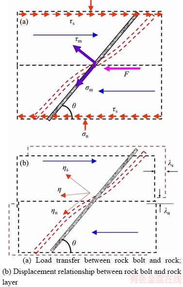
Figure 1 Mechanical model of bolted composite soft rock:
Let the transverse load applied on rock bolt be F induced by the shear sliding between upper soft rock and lower soft rock as shown in Figure 1(a). ��n is the normal stress, and ��S is the shear strength of joint surface. Unlike the rock bolt in single medium of rock mass, both transverse deformation and axial deformation will be induced in the anchorage body which crosses over the weak bedding plane of composite soft rock. According to the field situation, the bending stress of anchor bolt is analyzed based on Euler beam model. Obviously, the part near the joint surface will undergo the maximum transverse load. Let the average shear stress and average axial stress on the cross section of rock bolt at this position be ��m and ��m respectively.
Actually, the distribution of shear stress on the cross section of rock bolt under the action of bending deformation is very complicated. As shown in Figure 2, the distribution of shear stress exhibits as a parabolic along the height direction of circular bolt under the action of transverse force FS, and reaches the maximum at the neutral axis which is denoted as ��max. Relationship between average shear stress ��m and the maximum shear stress ��max is
 (1)
(1)
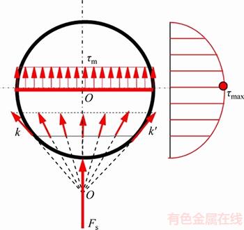
Figure 2 Shear stress distribution of circular rock bolt under action of transverse shear force
3 Analytical solution of anchoring effect on composite soft rock with weak bedding plane
Previous studies [24�C30] indicate that the transverse deformation of rock-bolt through layers not only exists at the bedding plane, but in a region which contains the joint surface. Let the bolt length in this region be as. The domain length of bolt near the joint surface where significant axial deformation is produced under bending is denoted as an.
In general, the reinforcement effect of rock bolt on composite soft rock exhibits in two aspects: one is the increasing of normal stress in rock mass near the joint surface, the other is the enhancement of shear strength of joint surface. Let the original shear strength of joint surface be
 (2)
(2)
where ��s is the friction angle, Cs is cohesion.
To simplify the analysis, the anchoring effect of single rock bolt is assumed to distribute evenly in anchorage zone near the joint surface. Let the cross section area of rock bolt be Am, and the equivalent area of rock layer in anchoring zone be As, according to Figure 1(a), the equivalent normal stress and tangential stress in the rock layer under the action of rock bolt is deduced as

 (3)
(3)
In fact, the shear strength of joint surface is the most impacted under the action rock-bolt through layers. Therefore, the relative increasing of shear strength is selected to quantify the reinforcement effect after the installation of rock bolt. Let the increased shear strength be ��SI, thus, the anchoring effect factor is defined as
 (4)
(4)
where ��SI=��S+��rm=(��n+��rm)tan��s+C+��rm. Apparently, the higher the �� is, the more obvious the anchoring effect is.
Figure 1(b) demonstrates the deformation relationship between rock mass and rock bolt near joint surface where ��s is the transverse shear deformation and ��n is the normal deformation of rock mass. ��s and ��n respectively stands for the lateral and axial deformation of rock bolt. Let the stiffness coefficient of joint surface in normal and tangential directions be Kn and Ks respectively, relationship between the stress and deformation of joint surface is calculated as

 (5)
(5)
Relationships between the stress and deformation of rock bolt in the two directions are

 (6)
(6)
where Gm and Em are the shear modulus and elastic modulus respectively. The integral results of Eq. (6) depend on the distribution of shear stress and axial force on the cross section of rock bolt in anchorage zone. For instance, if both satisfy the linear distribution, then
 ,
,  (7)
(7)
where ��s and ��n are related with the distribution function of shear stress and axial stress respectively.
According to Figure 1(b), deformation relationship between rock bolt and joint surface can be written as
 (8)
(8)
On the simultaneous expressions of Eqs. (3), (5), (7), (8), and relations ��=��n+��rm and ��SI=��S+��rm, the normal stress and tangential stress is respectively determined as

 (9)
(9)
where  and
and  which are related with the support stiffness of rock bolt. It is thus clear that the stiffness contribution of rock bolt on composite soft rock is composed of two parts, namely axial stiffness effect and shear stiffness effect (pin effect). According to Eq. (9), the displacements of rock bolt are established as
 (10)
(10)
where
 ,
,  ,
,
 ,
,  ,
,


Substituting Eq. (7) into Eq. (8), relationship between bolt stress and deformation of joint surface is deduced as
 (11)
(11)
By comprehensive utilization of Eqs. (4), (8), (9) and (11), the anchoring effect factor presented in Eq. (4) is derived as follows


 (12)
(12)
Obviously, the anchoring effect of rock-bolt through rock layer is closely related with the physical and geometric parameters of rock bolt and rock mass as well as joint surface. In fact, the displacement between rock layers is changing with the stress state, and this certainly will affect the stress distribution of rock bolt, so as to change the reinforcement effect. Thus, the anchoring effect factor is not a constant, but changing with the working state of composite soft rock.
On the other hand, the anchoring effect factor has its upper limitation due to the strength of rock bolt. Let yield condition of bolt satisfy the Mises yield criterion, that is
 (13)
(13)
Substituting Eq. (11) into Eq. (13), the equation characterizing the critical yield state of rock bolt in complex stress state is established as

 (14)
(14)
4 Numerical simulation of rock-bolt through rock layer
The anchoring effect of rock-bolt through layer was described in detail above by analytical method. However, the analytical solutions are difficult to establish due to the complex relations. In this part, a three dimensional calculation model of composite soft rock with rock bolt was established by finite element method in order to make clearly the mechanical behavior of rock bolt and soft rock layer during the failure process of joint surface.
4.1 Finite element model
Considering the symmetrical characteristic of geometry, half of the composite model was established as shown in Figure 3. For convenient analysis, the joint surface is assumed to be flat without considering the morphology influence of weak bedding plane. The dimension of rock layer at upper and lower is set as 150 mm��75 mm��150 mm. The diameters of rock bolt and grout are 20 mm and 25 mm, respectively. The model of rock mass, grout and rock bolt was respectively meshed by C3D8R element which called hexahedron reduced integral element with 8 node in ABAQUS. In order to simulate the interaction and loading transfer between rock bolt, grout and rock layer, three contact interfaces were set as shown in Figure 3(a). A hard contact model was adopted to describing the normal contact behavior considering the open behavior in normal direction. In tangential direction, the typical Coulomb friction model was applied considering the sticking and sliding behavior. Due to the symmetry of the model, each symmetry surface was fixed in normal direction. The transverse force was applied on the left surface (x) of rock 1 and right surface (x) of rock 2. Figure 3(b) showed the meshing result of composite model.
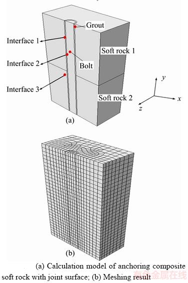
Figure 3 Calculation model of composite soft rock with rock bolt:
4.2 Constitutive model
A modified Mohr-Coulomb constitutive model was applied both on rock layer and grout. For rock bolt, due to the hardening behavior after yield point, the bilinear kinematic hardening constitutive model was employed [31]. The stress�Cstrain relation was set in accordance with the experimental results as shown in Figure 4. After highest point of hardening period, mechanical behavior of rock bolt shows as ideal plastic. However, the stress and strain obtained from laboratory are nominal, they should be converted to the true values through the following relations
 (15)
(15)
where �� and �� are the true strain and stress respectively.��norm and ��norm are the nominal.

Figure 4 Stress�Cstrain relationship of rock bolt
4.3 Bending deformation of rock bolt
Under the action of transverse force and normal stress of rock layer, significant bending deformation in rock-bolt through layer will be induced near the joint surface due to its shear slip. Figures 5 and 6 demonstrate the distribution curves of bending deformation and equivalent plastic strain of rock bolt along its axial direction when the cohesions of rock layer were set as 2, 6 and 10 MPa, respectively. Let the bending deflection of bolt axis be w, then
 (16)
(16)
where �� is the angle between the tangential direction of deflection curve and horizontal direction at plastic hinge.
Actually, the deflection curve of rock bolt between the two plastic hinges is approximately linear. The bending deformation is mainly induced in this region. The rock strength will directly affect the bending range. For instance, when cohesion is set as 2 MPa, the distribution range of bending deformation is 100 mm. However, this range will reduce to 79 mm while the cohesion of rock is increased to 6 MPa and 8 MPa, respectively.
It is clear that the deflection curves of rock bolt shown in Figure 5 appear as typical ��S�� type which can be fitted from nonlinear regression by
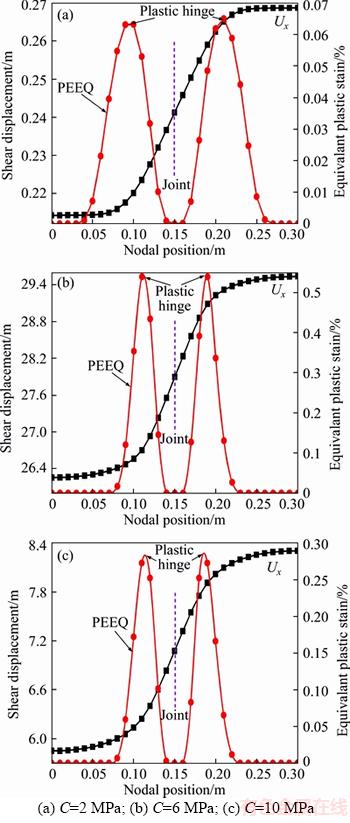
Figure 5 Distribution of bending deformation and equivalent strain of rock bolt under different rock strengths:
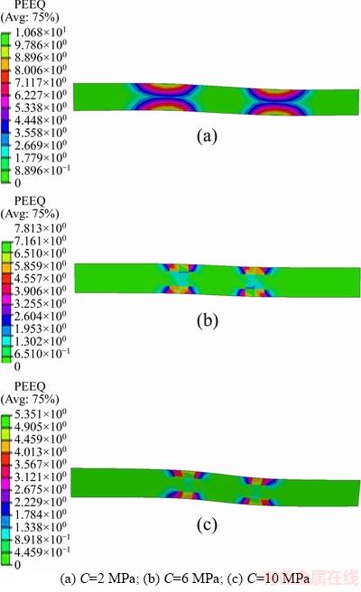
Figure 6 Contour of equivalent plastic strain in rock bolt under different rock strengths:
employing Doseresp model. The regression results are
 (C=2 MPa)
 (C=6 MPa)
 (C=10 MPa)
Comparison between the original data with regression results was demonstrated in Figure 7. The fitting precision is very high and correlation coefficients are all more than 99.9%.
4.4 Stress distribution in rock bolt
Concentrated zone of tensile and compression stress in rock bolt is generated on both sides of joint surface due to the significant bending deflection. Figure 8 represents the contour of axial stress in rock bolt along the axis. On the left side of joint surface, maximum tensile and compression stress are induced at the top and bottom of rock bolt respectively. However, the distribution is diametrically opposed on the right side. From Figure 6, it can be seen that the location of maximum stress just at the two plastic hinges.
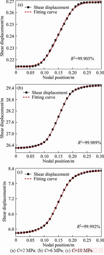
Figure 7 Comparison of fitting results of original data:
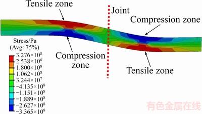
Figure 8 Contour of axial stress in rock bolt
Besides, relatively little axial stress is induced at the joint surface.
The distribution law of axial stress in rock bolt is presented in Figure 9. Due to the bending deflection under transverse force, the axial stress near joint surface region increases rapidly. As shown in Figure 5(a), rock bolt enters into the yielding state fast at two plastic hinges. But at the joint position, the axial stress is small. Rock bolt will present ideal plastic behavior after hardening stage, so the stress at plastic hinge will not obviously change even if the transverse force is further increased.
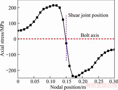
Figure 9 Distribution law of axial stress in rock bolt
Figure 10 demonstrates the contour of shear stress in rock bolt. Obviously, the maximum shear stress appears at the position of joint surface. The bending moment is approximately 0 from above analysis. Taking the central part of rock bolt as monitoring elements, the distribution curve of shear stress along the axial direction is presented in Figure 11. No shear stress is induced at plastic hinges. It is rapidly increased to the maximum from plastic hinge to joint position.
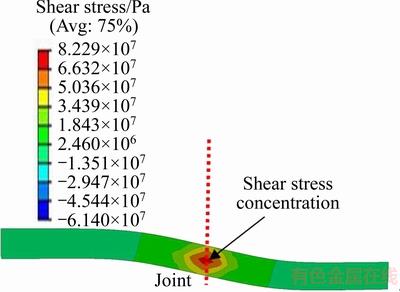
Figure 10 Contour of shear stress in rock bolt
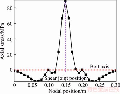
Figure 11 Distribution law of shear stress along axial direction in rock bolt
4.5 Distribution of plastic failure region in composite soft rock
Shear sliding will be induced on the joint surface under the action of transverse force as shown in Figure 12. With the increasing of shear displacement, significant stress concentration is generated in soft rock near the joint surface due to the strong reaction of rock bolt which is induced by the large bending deformation. So these zones are prone to crushing. In Figure 12, the distribution law of equivalent strain in composite rock under the action of transverse force when C is set as 2 MPa was also presented. Evidently, the equivalent plastic strain in these zones near the joint surface is obviously higher than the other part. This implies that the zones in composite soft rock near joint surface are the first to failure which causes the loosening failure of anchorage body.
Large difference of plastic zone in soft rock exhibits near the joint surface according to different rock strengths. Figure 13 shows the different distributions of plastic zone in composite soft rock with different cohesions. Due to the pin effect of rock bolt, significant compression failure zone is produced in soft rock layer near the joint surface. The lower the rock strength is, the greater the distribution range failure area is. As the result shown, the failure zones are significantly reduced when the cohesion is increased to 10 MPa.

Figure 12 Distribution law of shear displacement and equivalent plastic strain in soft rock
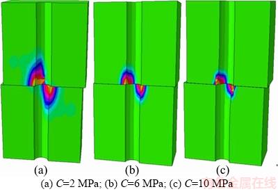
Figure 13 Contour of failure zones in soft rock with different strengths:
5 Conclusions
In this paper, theoretical and numerical analysis were carried out for the anchoring effect of rock-bolt through layer in composite soft rock of western mining area of China. A quantitative evaluation method was proposed from theoretical study. Based on the numerical simulation, the bending behavior of rock bolt and failure characteristics of soft rock near the joint surface were made clearly. All the conclusions are drawn as follows:
1) The anchoring effect of rock-bolt through layer exhibits mainly on the shear strength of joint surface in composite soft rock. This effect can be quantified by a factor d. From its analytical expression, it is found that this factor is not a constant but changing with the working condition of composite soft rock which is closely related with the physical and geometric parameters of composite model.
2) The bending deformation of rock bolt is mainly distributed between the two plastic hinges, and the bending curve can be regressed from Doseresp model. The bending displacement of rock bolt is closely related with the rock strength. At the plastic hinge, the maximum tensile and compression stress are produced on the edge of rock bolt. At the position of joint surface, shear stress is concentrated in the middle of rock bolt and the bending moment is approximate 0. The shear stress rapidly reduced from the joint surface to the plastic hinge.
3) Due the strong reaction of rock bolt, significant stress concentration is produced in the soft rock near the joint surface. This leads to the compression failure zones in this area. The range of failure area is closely related with rock strength.
References
[1] TAN Y L, LIU X S, NING J G, LU Y W. In situ investigations on failure evolution of overlying strata induced by mining multiple coal seams [J]. Geotechnical Testing Journal, 2017, 40(2): 1�C14. DOI: 10.1520/GT J20160090.
[2] ZHAO Z H, WANG W M, WANG L H. Theoretical analysis of a new segmented anchoring style in weakly cemented soft surrounding rock [J]. International Journal of Mining Science and Technology, 2016, 26(3): 401�C407. DOI: 10.1016/ j.ijmst.2016.02.006.
[3] ZHANG Le-wen, WANG Ren. Research on status quo of anchorage theory of rock and soil [J]. Rock and Soil Mechanics, 2002, 23(5): 627�C631. (in Chinese)
[4] PHILLIPS S. Factors affecting the design of anchorage sin rock [M]. London: Cementation Research Ltd., 1970.
[5] MA S, NEMCIK J, AZIZ N. An analytical model of fully grouted rock bolts subjected to tensile load [J]. Construction and Building Materials, 2013, 49: 519�C526. DOI: 10.1016/ j.conbuildmat.2013.08.084.
[6] REN F F, YANG Z J, CHEN J F, CHEN W W. An analytical analysis of the full-range behavior of grouted rockbolts based on a tri-linear bond-slip model [J]. Construction and Building Materials, 2010, 24(3): 361�C370. DOI: 10.1016/ j.conbuildmat.2009.08.021.
[7] XIAO Shu-jun, CHEN Chang-fu. Mechanical mechanism analysis of tension type anchor based on shear displacement method [J]. Journal of Central South University of Technology, 2008(S1): 106�C111. DOI: 10.1007/ s11771 -008-0021-z.
[8] HE Si-ming, LI Xin-po. Study on mechanism of prestressed anchor bolt [J]. Chinese Journal of Rock Mechanics and Engineering, 2006, 25(9): 1876�C1880. (in Chinese)
[9] MUYA M S, HE B, WANG J T, LI G C. Effects of rock bolting on stress distribution around tunnel using the elastoplastic model [J]. Journal of Earth Science, 2006, 17(4): 337�C341. DOI: 10.1016/S1002-0705(07)60008-9.
[10] GOEL R K, ANIL S, SHEOREY P R. Bolt length requirement in underground openings [J]. International Journal of Rock Mechanics and Mining Sciences, 2007, 44(5): 802�C811. DOI: 10.1016/j.ijrmms.2006.12.001.
[11] LIU H Y, SMALL J C, CARTER J P. Full 3D modelling for effects of tunnelling on existing support systems in the Sydney region [J]. Tunnelling and Underground Space Technology, 2007, 17(5): 569�C572. DOI: 10.1016/j.tust. 2007.06.009.
[12] KILIC A, YASAR E, ATIS C D. Effect of bar shape on the pull out capacity of fully grouted rockbolts [J]. Tunneling and Underground Space Technology, 2003, 18(1): 1�C6. DOI: 10.1016/S0886-7798(02)00077-9.
[13] KILIC A, YASAR E, CELIK A G. Effect of grout properties on the pull out load capacity of fully grouted rock bolt [J]. Tunneling and Underground Space Technology, 2002, 17(4): 355�C362. DOI: 10.1016/S0886-7798(02)00038-X.
[14] BENMOKRANE B, CHENNOUF A, MITR H S. Laboratory evaluation of cement based grouts and grouted rock anchors [J]. International Journal of Rock Mechanics and Mining Sciences & Geomechanics Abstracts, 1995, 32(7): 633�C642. DOI: 10.1016/0148-9062(95)00021-8.
[15] BENMOKRANE B, XUE X H, BELLAVANCE E. Bond strength of cement grouted glass fibre reinforce plastic (GFRP) anchor bolts [J]. International Journal of Rock Mechanics and Mining Sciences & Geomechanics Abstracts, 1996, 33(5): 455�C465. DOI: 10.1016/0148-9062(96)00006- X.
[16] HOU Chao-jiong, GOU Pan-feng. Mechanism study on strength enhancement for the rocks surrounding roadway supported by rock [J]. Chinese Journal of Rock Mechanics and Engineering, 2000, 19(3): 342�C345. (in Chinese)
[17] YANG Shuang-suo, ZHANG Bai-sheng. The influence of bolt action force to the mechanical property of rocks [J]. Rock & Soil Mechanics, 2003, 24(S1): 279�C282. (in Chinese)
[18] SAWWAF M E, NAZIR A. The effect of soil reinforcement on pullout resistance of an existing vertical anchor plate in sand [J]. Computers and Geotechnics, 2006, 33(3): 167�C176. DOI: 10.1016/j.compgeo.2006.04.001.
[19] ZOU Zhi-hui, WANG Zhi-lin. Mechanism of anchor bar in different elastic modulus rocks by model test [J]. Chinese Journal of Geotechnical Engineering, 1993, 16(5): 71�C78. (in Chinese)
[20] LIU Ai-qing, JU Wen-jun, HU Hai-tao, WANG Xiang. Experimental study on the effect of bolt prestress on the shear behavior of jointed rockmass [J]. Journal of China Coal Society, 2013, 38(3): 391�C396. (in Chinese)
[21] LU Li, ZHANG Si-ping, ZHANG Yong-xing, LIN Wei-xun. Configuration optimization of pressure-dispersive anchors in soft-hard interbed of sedimentary rock [J]. Chinese Journal of Rock Mechanics and Engineering, 2010, 29(S2): 4124�C4130. (in Chinese)
[22] YANG Jian-hui, XIA Jian-zhong. Test study on the complete deformation property of bolted stratified surrounding rockmasses [J]. Journal of China Coal Society, 2005, 30(4): 414�C417. (in Chinese)
[23] LI Xin-ping, WANG Tao, SONG Gui-hong, GUO Yun-hua, ZHANG Cheng-liang. Study on composite anchoring theory and numerical simulation test on layered rocks [J]. Chinese Journal of Rock Mechanics and Engineering, 2006, 25(S2): 3654�C3660. (in Chinese)
[24] CAO C, NEMCIK J, REN T, AZIZ N. A study of rock bolting failure modes [J]. International Journal of Mining Science and Technology, 2013, 23(1): 79�C88. DOI: 10.1016/ j.ijmst.2013.01.012.
[25] SONG H W, DUAN Y Y, YANG J. Numerical simulation on bolted rock joint shearing performance [J]. International Journal of Mining Science and Technology, 2010, 20(3): 460�C465. DOI: 10.1016/S1674-5264(09)60226-X.
[26] GHABRAIE B, GHABRAIE K, XIE Y M. A study on truss bolt mechanism in controlling stability of underground excavation and cutter roof failure [J]. Geotechnical and Geological Engineering, 2013, 31(2): 667�C682. DOI: 10.1007/s10706-013-9617-7.
[27] JALALIFAR H, AZIZ N. Analytical behavior of bolt�Cjoint intersection under lateral loading conditions [J]. Rock Mechanics and Rock Engineering, 2010, 43(1): 89�C94. DOI: 10.1007/s00603-009-0032-6.
[28] KAMAL C D, DEBASIS D, JHA A K. An enhanced numerical procedure for modelling fully grouted bolts intersected by rock joint [J]. Geosystem Engineering, 2013, 16(1): 37�C46. DOI:10.1080/12269328.2013.780738.
[29] MARTIN L B, TIJANI M, HADJ-HASSEN F, NOIRET A. Assessment of the bolt-grout interface behavior of fully grouted rockbolts from laboratory experiments under axial loads [J]. International Journal of Rock Mechanics & Mining Sciences, 2013, 63: 50�C61. DOI: 10.1016/ j.ijrmms. 2013. 06. 007.
[30] JALALIFAR H, AZIZ N, HADI M N S. Non-linear analysis of bolt-grout-concrete interaction in reinforced shear joint [J]. Journal of Mines, Metals and Fuels, 2004, 52(9): 208�C216. https://www.researchgate.net/publication/289400703_Non-linear_analysis_of_bolt-grout-concrete_Interaction_in_reinforced_shear_joint.
[31] JALALIFAR H, AZIZ N. Numerical simulation of fully grouted rock bolts [M]// Numerical Simulation-From Theory to Industry, Dr. Mykhaylo Andriychuk (Ed), InTech, 2012: 607�C640. DOI: 10.5772/48287.
(Edited by HE Yun-bin)
���ĵ���
�������Ҵ���ê��ЧӦ�����ۺ���ֵģ���о�
ժҪ���������ҵ�ê�̻�����ê��ʧЧ������ͬ�ڵ�һ����ê�̡�������������������Ҷ���ê�����⣬�����Ҳ��ĺ�����л��ƣ������˺��������渴������ê�̵���ѧģ�ͣ��������ê��ЧӦ������������ê�˵�ê��ЧӦ���Ӽ�ê��������ı����ƻ����̳���, �о���ϵͳê�˵ļӹ�Ч�������, �����ӹ�Ч���ݻ����̣���������Ԫ��������һ�������˸�������ê�̵���ֵ����ģ�ͣ������������ں����غ������£������渽��ê�˺�����ı���������Ӧ���ֲ������Լ��ƻ���Ϊ�������о��������������ê�˵ļӹ�ЧӦ��ê�˵ĸնȲ��������β�����Χ�ҵĸնȲ����ͼ��β������йء�ê��ЧӦ������һ������Χ�ҹ���״̬�ı���仯����������ֵ����������ê���ں�����������µ����۱�����Ҫ�����ڽ����渽���������Խ�֮�䣬�������߿���Doserespģ�ͽ��б�������2�����Խ´���ê�˴��������ѹӦ�����ڽ����洦����������Ӧ�������������ڽ����渽������ê�˵ķ��������ȳ��������ƻ��������Ͻ��Ϊ��һ���о���������ê��ʧЧ�춨�����ۺͼ��������
�ؼ��ʣ��������ң�ê�̣��ݻ����̣���ֵģ�ͣ��ܽ���
Foundation item: Projects(51774196, 41472280, 51578327) supported by the National Natural Science Foundation of China; Project(2016M592221) supported by the China Postdoctoral Science Foundation; Project(BJRC20160501) supported by the SDUST Young Teachers Teaching Talent Training Plan, China
Received date: 2017-07-19; Accepted date: 2017-11-17
Corresponding author: ZHAO Zeng-hui, PhD; Tel: +86�C32�C86057945; E-mail: tgzyzzh@163.com; ORCID: 0000-0002-6335-1655
Abstract: Anchoring mechanism and failure characteristics of composite soft rock with weak interface usually exhibit remarkable difference from those in single rock mass. In order to fully understand the reinforcement mechanism of composite soft roof in western mining area of China, a mechanical model of composite soft rock with weak interface and rock bolt which considering the transverse shear sliding between different rock layers was established firstly. The anchoring effect was quantified by a factor defined as anchoring effect coefficient and its evolution equation was further deduced based on the deformation relationship and homogenized distribution assumption of stress acting on composite structure. Meanwhile, the numerical simulation model of composite soft rock with shear joint was prompted by finite element method. Then detailed analysis were carried out for the deformation features, stress distribution and failure behavior of rock mass and rock bolt near the joint under transverse load. The theoretical result indicates that the anchoring effect of rock-bolt through weak joint changes with the working status of rock mass and closely relates with the physical and geometric parameters of rock mass and rock bolt. From the numerical results, the bending deformation of rock bolt accurately characterized by Doseresp model is mainly concentrated between two plastic hinges near the shear joint. The maximum tensile and compression stresses distribute in the plastic hinge. However, the maximum shear stress appears at the positions of joint surface. The failure zones of composite rock are produced firstly at the joint surface due to the reaction of rock bolt. The above results laid a theoretical and computational foundation for further study of anchorage failure in composite soft rock.
