

Effect of cerium on microstructure and mechanical properties of Sn-Ag-Cu system lead-free solder alloys
ZHAO Xiao-yan(��С��), ZHAO Mai-qun(����Ⱥ), CUI Xiao-qing(��С��),
XU Tian-han(���캵), TONG Ming-xin(������)
School of Materials Science and Engineering, Xi��an University of Technology, Xi��an 710048, China
Received 31 August 2006; accepted 2 April 2007
Abstract:
The melting point, spreading property, mechanical properties and microstructures of Sn-3.0Ag-2.8Cu solder alloys added with micro-variable-Ce were studied by means of optical microscopy, scanning electron microscopy(SEM) and energy dispersive X-ray(EDX). The results indicate that the melting point of Sn-3.0Ag-2.8Cu solder is enhanced by Ce addition; a small amount of Ce will remarkably prolong the creep-rupture life of Sn-3.0Ag-2.8Cu solder joint at room temperature, especially when the content of Ce is 0.1%, the creep-rupture life will be 9 times or more than that of the solder joint without Ce addition; the elongation of Sn-3.0Ag-2.8Cu solder is also obviously improved even up to 15.7%. In sum, the optimum content of Ce is within 0.05%-0.1 %.
Key words:
Sn-Ag-Cu system; lead-free solder alloy; melting point; spreading property; mechanical property;
1 Introduction
Sn-Pb soldering for metal interconnections has a long history, dating back 2 000 years. These alloys are the dominant solders used widely in manufacture because of their unique combination of material properties, such as easy handling, low melting temperatures, good workability, ductility and excellent wetting on Cu and its alloys[1-3]. It is well known that conventional Pb- containing solders are harmful to both people��s health and environment, so the exploration of lead-free solders as substitute of lead-tin alloys is paid more attention [4-7].
The lead-free solders used in electronic industry need to meet a series of standards: good wettability, low melting point, low cost and adequate strength. At present, a number of investigations have been carried out on such promising lead-free solder alloys as Sn-Ag, Sn-Cu, Sn-Zn, Sn-Bi and Sn-In. Among these alloys, the Sn-Ag-Cu system solder becomes one of the most future solders because its excellent wetting and mechanical properties. However, it also has some disadvantages, such as poor creep-rupture and low elongation. In order to deal with these problems, the rare earth(RE) was added into the Sn-Ag-Cu system. The RE has some unique properties that make it have extensive applications in material and metallurgy field. The grain size of Sn-9Zn eutectic solders can be decreased obviously with only 0.05% RE added[8], the tensile properties and anti-fatigue strength of Sn-Ag-Bi solders can be improved with adding RE[9].
This work aimed to investigate the influence of various contents of Ce on microstructure and mechanical properties of Sn-Ag-Cu system solder alloys.
2 Experimental
2.1 Alloy design and preparation
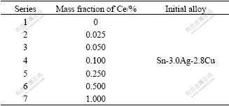
The raw materials are combined with analytically pure Sn, Ag, Cu and RE that is simplex Ce (98%). The compositions of experimental solder alloys are listed in Table 1. First, the raw material Sn was placed into an Al2O3 ceramic crucible, and the eutectic salt (m(KCl)? m(LiCl)=3?1) was used over the surface to prevent from oxidizing[10]. When the furnace temperature reached 580 ��, the ceramic crucible was put into furnace to melt for 5 min. After Sn was melted completely, Ag and Cu were pushed into the melted-Sn liquid alloy with the help of a stainless steel facility, 3 min later, the same process was used with Ce. After Ce was melted, the melted alloy was held for 120 min. During the process, a stainless steel rod was used every 10 min to make the solder alloy homogenized. At last, the melted solder was chill-cast into a rod.
Table 1 Composition of examined solder alloy
2.2 Experimental procedure
1) The testing of melt-temperature
The liquidus and solidus temperatures of the solders were tested by thermal analysis method.
2) The testing of spreading
The specimen was made into d12 mm, 0.8 g wafer, and the surface of specimen was made smooth. The substrates were copper pad with 40 mm��40 mm��1 mm, and the substrates were polished with 400# sandpaper to ensure a pure surface, then put into HCl for 1 min to eliminate oil, oxide and other impurity. At the end the substrates were cleaned with alcohol, and then made dry. The specimen was placed on the center of copper pad, then flux was used to cover the specimen and the copper was put into the resistance stove. The specimen was maintained at 300 �� for 20 min, then taken out and measured the spreading areas of solders.
3) Microstructure observation
The specimens were made by general method, then etched with corrosive solution (V(CH4)?(HNO3)? V(HCl)=93?5?2). The microstructure of specimen was observed by XJL-03 optical microscopy (OM). The components were analyzed with AMRAY-100B scanning electron microscopy(SEM) and energy dispersive X-ray (EDX).
4) Creep-rupture life test
The single-lap shear joint areas are 2 mm��2 mm, and the substrate is copper sheet. The fabrication on Cu substrate was cleaned with a solution of 50% HNO3 and 50% CH3H2OH. Solder mask IF710 was spread upon the surface of the narrow end of the Cu substrate to obtain a 4 mm2 cross-sectional area. The lamellas of solders were cut into a quadrate (2 mm��2 mm), and then the rosin flux was covered with each cross-sectional area. A thin solder, whose area is 4 mm2, was sandwiched between two Cu sheets, then this solders was performed and put into the stove, held at 300 �� for 10 min. The specimen was cooled at room temperature. The creep-rupture life test was performed in the DL302 box that can control the temperature and wet with a dead loading of 8.75 MPa at 25 ��, and the fracture time was recorded automatically. The microstructure of solder section was examined by AMRAY-1000B scanning electron microscope(SEM).
5) The tensile test
Tensile tests were carried out on d8 mm specimens and the length of the gauge is 40 mm. The specimens were annealed at 100 �� for 1 h to prevent it from creeping deformation before test. The tests were carried out on an Instron tensile test machine at a strain rate of 1.0��10-3 s-1 at room temperature. The microstructure of specimen was examined by AMRAY-1000B scanning electron microscope(SEM).
3 Results and analysis
3.1 Melting characteristics analysis
The solidus temperature and liquidus temperature of alloy were tested by thermal analysis method. According to the solid point and liquid point, the curves are shown in Fig.1. As shown in Fig.1, the addition of mirco-Ce has a trifling effect on the melting temperature of Sn-3.0Ag-2.8Cu.The liquidus temperature is within 212-220 ��. This small amount of RE makes the temperature of liquidus and solidus upward. Because the melting temperature of Ce is 3-4 times as high as that of SnAgCu sample, the melting temperature of the alloy rises slightly after adding Ce.
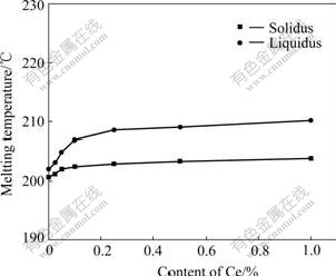
Fig.1 Melting temperature of Sn-3.0Ag-2.8Cu-Ce solder alloys
3.2 Spreading analysis
To some degree, the spreading property of solder is up to its wettability under a certain environment. The spreading areas of Sn-3.0Ag-2.8Cu with different contents of Ce are listed in Table 2.
Table 2 Spreading areas of Sn-3.0Ag-2.8Cu-Ce solder alloys
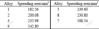
It is obvious that the spreading area of the specimen 4# is the largest in Table 2. When the content of Ce is less than 0.1%, the spreading area of Sn-3.0Ag-2.8Cu-Ce increases gradually with the addition of Ce. When the content of Ce is over 0.1%, there is a tendency for the spreading area to decrease.
Two reasons lead to the result: on one hand, RE is a surface-active element that can lower the surface tension of liquid solder to favor the wetting of the solder on the substrate[11]; on the other hand, RE is easy to be oxidated, so the formation of oxide residue during soldering will lessen the wettability of the solder, thereby affect the spreading properties. The effect is more and more obvious with the increase of RE and exceeds the favorable aspect of RE. To sum up, the content of Ce should not exceed 0.1% when adding Ce into the Sn-3.0Ag-2.8Cu solders.
3.3 Microstructure analysis
Fig.2 shows the microstructure of the solder with different contents of Ce. As shown in Fig.2, the microstructure of solders becomes finer and finer, and its distribution becomes more and more homogeneous as the content of Ce increasing. Small amount of Ce is absorbed by the boundary of intermetallic compound(IMC) and provides inhomogeneous center of nucleation, then change the growth velocities of crystal along with various crystalline directions[12]. Fig.2(a) shows that the microstructure of Sn-3.0Ag-2.8Cu under the OM is irregular block-like. When the content of Ce is 0.025%, the crystal grain in Fig.2(b) is much finer than that in Fig.2(a). When the content of Ce is up to 0.05%, the is shaped bar-like or short rod-like as in Fig.2(c). With the content of Ce increasing, the microstructure becomes finer and finer. When the content of Ce is up to 0.1%, the microstructure becomes eutectic structure and more homogeneous, as shown in Fig.2(d).
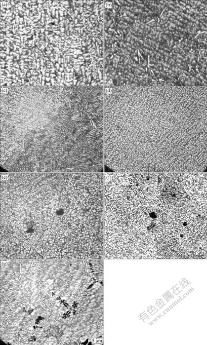
Fig.2 Microstructures of alloy specimens: (a) Sn-3.0Ag-2.8Cu; (b) Sn-3.0Ag-2.8Cu- 0.025Ce; (c) Sn-3.0Ag-2.8Cu-0.05Ce; (d) Sn-3.0Ag-2.8Cu-0.10Ce; (e) Sn- 3.0Ag-2.8Cu-0.025Ce; (f) Sn-3.0Ag- 2.8Cu-0.50Ce; (g) Sn-3.0Ag-2.8Cu-1.0Ce
Figs.2(e), (f) and (g) show that the black new phase begins to appear in the microstructure with Ce increasing. With the content of Ce increasing, the new black phase increases evidently, and the shape of RE phase takes on a block-like, snow-like or fishbone-like as shown in Fig.3. The microstructure is composed of a Sn-rich phase, rod-like Cu6Sn5 and grain Ag3Sn by SEM and EDX analysis. The results show that black new phase is RE compound phase, the white around is ternary eutectic structure of SnAgCu and the dark in the middle is Sn-Ce phase. As shown in Fig.3, although Sn, Ag, Cu and Ce all can form IMC, the reaction temperature of Sn-Ce is lower than 300 �� and those of Ce-Ag and Sn-Cu are more than 300 ��, so Ce and Sn can form IMC easier[7].
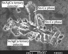
Fig.3 Microstructure of fish-bone shape RE phase
The finer and more homogeneous microstructure can have a favorable effect on the mechanical properties of the alloy, but the phases of RE compound have an adverse effect on them.
3.4 Creep-rupture life analysis
The structure of the alloy is improved noticeable by the minute amount of RE added, so creep-rupture time of specimen is one of the important mechanical properties of solders. The authors believe that the mechanical properties of alloy should be improved likewise. Fig.4 shows the creep-rupture life of solder with different contents of Ce.
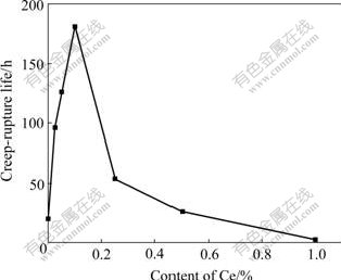
Fig.4 Effect of Ce content on creep-rupture life of Sn-3.0Ag- 2.8Cu solder joint
Fig.4 shows that Ce can prolong markedly the creep-rupture life of Sn-3.0Ag-2.8Cu of solder joint at room temperature. When the content of Ce is 0.1%, the creep-rupture life is the longest, up to 9 times more than Sn-3.0Ag-2.8Cu. Because a minute amount of Ce can make the structure homogeneous and fine, and decrease the strain around the crystal boundary, then prevent the nucleation of hole[13-14], therefore the creep-rupture life is enhanced.
When the content of Ce exceeds 0.1%, the creep-rupture life of joint shows decline tendency. Especially, when Ce is up to 1.0%, the creep-rupture life of joint is even lower than that of Sn-3.0Ag-2.8Cu.The reason is that, as the content of Ce increases, the hard brittle RE compound phase also increases, then the creep-rupture life of solders decreases. So the content of Ce should be less than 0.1% in the alloy of Sn-3.0Ag- 2.8Cu.
Fig.5 shows the microstructure of creep-rupture. The shape and denseness distribution of dimple can be clearly seen. With Ce addition, the fractured microstructure is the mixture of dimple and cleavage, which shows that the ductile is worse. Just as shown in Fig.5(a), the distribution of dimple is unhomogeneous.
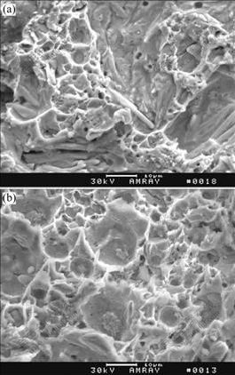
Fig.5 Microstructures of creep-rupture samples: (a) Sn-3.0Ag- 2.8Cu; (b) Sn-3.0Ag-2.8Cu-0.1Ce
The distribution of dimple is improved clearly by RE Adding, as shown in Fig.5(b). When the content of Ce is 0.1%, the fracture of specimen is pure dimple. Because after adding Ce, the structure becomes finer and more homogeneous, thereby the creep-rupture life is improved obviously.
3.5 Tensile property
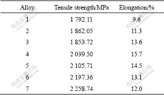
Table 3 lists the relationship between the content of Ce and tensile strength. It is easily seen that Ce has some effect on mechanical properties of Sn-3.0Ag-2.8Cu solders, which enhances the tensile strength and improves the elongation obviously. When the content of Ce is 0.1%, the elongation is up to 15.7%, which indicates that Ce can improve the ductile of alloy solders. When Ce exceeds 0.1%, the elongation deceases gradually with the increase of Ce. According to Hall- Petch relationship ��y=��0+kyd-1/2, when the grain size decreases, the ratio between the grain surface and volume increases, thus the function between interface energy and grain around strengthens. Interface energy can make the lattice near the surface layer of grain distortional. Interaction of the grain around also causes lattice that lies on the surface layer of grain distort. Due to the affection of interface energy, there appears a district that hinders crystal from deformation near the grain boundary. The finer the grain, the wider the district of difficult deformation [15-16]. More strength is needed to make it slip, that is to say, the strength resistant of deformation increases. The increase of resistant of deformation means the increase of strength.
Table 3 Results of tensile tests of examined Sn-3Ag-2.8Cu-Ce solder alloys
The microstructures of tensile specimens are shown in Fig.6. The tensile fracture-surface of Sn-3.0Ag-2.8Cu is smooth and light obviously, and shows a brittle fracture as shown in Fig.6(a). When adding 0.1% Ce, the fracture-surface is dark and not very smooth and has a with fibrous shape as shown in Fig.6(b). When Ce addition exceeds 0.1% as shown in Fig.6(c), it changes into hard brittle fracture evidently. This is because of the appearance of the hard brittle RE compound in the solders. As Ce addition increases, the content of RE compound increases obviously, and the dimple in the fracture-surface deceases sharply, so the elongation of solders reduces distinctly.
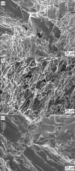
Fig.6 Microstructures of tensile specimens:(a) Sn-3.0Ag- 2.8Cu; (b) Sn-3.0Ag-2.8Cu-0.1Ce; (c) Sn-3.0Ag- 2.8Cu-0.5Ce
4 Conclusions
1) A minute amount of single Ce will ratherish elevate the liquidus temperature and solidus temperature of Sn-3Ag-2.8Cu.
2) The maximum spreading area appears when the content of Ce is 0.1%, and the spreading area decreases when the content of Ce exceeds 1.0%.
3) The addition of Ce can obviously prolong the creep-rupture life of solder joint at room temperature. When the content of Ce is 0.1%, the creep-rupture life is 9 times or more than that of Sn-3.0Ag-2.8Cu without Ce. However, when the content of Ce exceeds 0.1%, the creep-rupture life of solders joint decreases.
4) The addition of Ce can obviously improve the elongation of Sn-3.0Ag-2.8Cu solder to 15.7% and the tensile strength is also improved.
References
[1] SUGANUMA K. Advances in lead-free electronics soldering [J]. Current Opinion in Solid State and Materials Science, 2001, 5: 55-64.
[2] YU D Q, ZHAO J, WANG L. Improvement on the microstructure stability, mechanical and wetting properties of Sn-Ag-Cu lead-free solder with the addition of rare earth elements [J]. Journal of Alloys and Compounds, 2004, 376: 170-175.
[3] HUANG M L, WU C M L, LAI J K L, WANG L, WANG F G. Lead free solder alloys Sn-Zn and Sn-Sb prepared by mechanical alloying [J]. Journal of Materials Science: Materials in Electronics, 2000, 11(1): 57-65.
[4] XU Tian-han, ZHAO Mai-qun, LIU Xin-hua. Study on the optimal free-lead solder alloy of Sn-Ag-Cu system [J]. Electronic Components and Materials, 2004, 23(8): 14-17.
[5] AHAT S. Microstructure and shear strength evolution of SnAg/Cu surface mount solder joint during aging [J]. Journal of Electronic Materials, 2001, 30(10): 1317-1322.
[6] SHIUE R K, TSAY L W, LIN C L, OU J L. A study of Sn-Bi-Ag-In lead-free solders [J]. Journal of Materials Science, 2003, 38: 1269-1279.
[7] KIM Y S, KIM K S, HWANG C W, SUGANUMA K. Effect of composition and cooling rate on microstructure and tensile properties of Sn-Zn alloys [J]. Journal of Alloys and Compounds, 2003, 352: 237-245.
[8] WU C M L, YU D Q, C M T. The properties of Sn-9Zn lead-free solder alloys doped with trace rare earth elements [J]. Journal of Electronic Materials, 2002, 31(9): 921-927.
[9] XIA Zhi-dong, SHI Yao-wu, CHEN Zhi-gang. Evaluation on the characteristics of tin-silver-bismuth solder [J]. Journal of Materials Engineering and Performance, 2002, 11(1): 107-111.
[10] YU Da-quan, ZHAO Jie, WANG Lai. Wetting properties of Sn-9Zn alloy with trace rare earth elements [J].The Chinese Journal of Nonferrous Metals, 2003, 13(4): 1001-1011. (in Chinese)
[11] CHEN Z G, SHI Y W, XIA Z D, YAN Y F. Properties of lead-free solder SnAgCu containing minute amount of rare earth [J]. Journal of Electronic Materials, 2003, 32(4): 235-243.
[12] XIA Zhi-dong. Effect of rare earth element addition on the microstructure and mechanical properties of tin-sliver-bismuth solder [J]. Journal of Materials Science, 2002, 31(6): 564-569.
[13] FENG Wu-feng, WANG Chun-qing, LI Ming-yu. Development and design methods of solder alloy applied in joining electronic components [J]. Electronics Process Technology, 2000, 21(2): 47-59.
[14] WU C M L, YU D Q, LAW C M T, WANG L. Microstructure and mechanical properties of new leas-free Sn-Cu-RE solder alloys [J]. Journal of Electronic Material, 2002, 31(9): 928-932.
[15] CHEN Cun-zhong. The fusion metallurgy and chill of nonferrous metals [M]. Beijing: Metallurgical Industry Press, 1988: 109-110. (in Chinese)
[16] ZHANG Shi-jun, LI Wen-xian, YU Kun. The effect of Ce on the grain size and as-cast mechanical properties of magnesium alloy AZ31 [J]. Foundry, 2002, 51(12): 767-781.
Foundation item: Project(2002E111) supported by the National Basic Research Priorities Program of Shanxi Province, China; Porject(03JC14) supported by the Industry Project of Shanxi Province Education, China
Corresponding author: ZHAO Xiao-yan; Tel: 13038583825; E-mail: zhaomq@mail.xaut.edu.cn
